
Create successful ePaper yourself
Turn your PDF publications into a flip-book with our unique Google optimized e-Paper software.
Technical Handbook<br />
<strong>Friction</strong> <strong>Stir</strong> <strong>Welding</strong>
Contents<br />
page page<br />
Introduction 4<br />
Process principles 6<br />
Weldable alloys 6<br />
Process characteristics 7<br />
<strong>Welding</strong> parameters 7<br />
Tools 7<br />
Design principles 8<br />
Tools for steels 8<br />
Retractable pin tool 8<br />
Bobbin tool 10<br />
Process speed 10<br />
Aluminium 13<br />
Application areas 15<br />
Aerospace 15<br />
Space industry 15<br />
Civil aviation 16<br />
Aerospace R&D 16<br />
Shipbuilding 18<br />
Application advances 18<br />
Parts and components 19<br />
Automotive industry 21<br />
Automotive applications 22<br />
Tailor welded blanks (TWB´s) 27<br />
Superplastic forming 27<br />
Extruders and extrusions<br />
– with special focus on rolling-stock panels 28<br />
Steel and other high-temperature materials 30<br />
Application examples 32<br />
Case study: Swedish Nuclear 32<br />
Case study: Marine Aluminium a.s, Norway 35<br />
Equipment 37<br />
Full-scale automation for<br />
high-volume applications 37<br />
Modular flexibility for<br />
“standard” applications 37<br />
Robotised for more complex applications 37<br />
Quality and enviromental aspects 39<br />
Environmental aspects of <strong>Friction</strong> <strong>Stir</strong> <strong>Welding</strong> 39<br />
Less weld-seam preparation 39<br />
Fewer resources 39<br />
Noise, an underestimated health threat 39<br />
Energy saving FSW process 39<br />
Less post-treatment and impact<br />
on the environment 39<br />
<strong>Friction</strong> <strong>Stir</strong> Welded components offer<br />
through-life environmental gains 40<br />
Quality 40<br />
Economics 41<br />
Example of cost analysis 42<br />
Compared to arc welding 44<br />
Conclusions 46<br />
DISCLAIMER<br />
Whilst all reasonable efforts have been made to ensure the accuracy of the information contained in<br />
this handbook at the time of going to press, ESAB gives no warranty with regard to its accuracy or<br />
completeness. It is the responsibility of the reader to check the accuracy of the information<br />
contained in this handbook, read product labels and equipment instructions and comply with current<br />
regulations. If the reader is in any doubt with regard to the proper use of any technology they should<br />
contact the manufacturer or obtain alternative expert advice. ESAB accepts no responsibility or<br />
liability for any injury, loss or damage incurred as a result of any use or reliance upon the information<br />
contained in this handbook.<br />
3
Introduction to the<br />
FSW Technical Handbook<br />
<strong>Friction</strong> <strong>Stir</strong> <strong>Welding</strong> (FSW) was invented by Wayne<br />
Thomas at TWI (The <strong>Welding</strong> Institute), and the first<br />
patent applications were filed in the UK in December<br />
1991. Initially, the process was regarded as a<br />
“laboratory” curiosity, but it soon became clear that<br />
FSW offers numerous benefits in the fabrication of<br />
aluminium products.<br />
<strong>Friction</strong> <strong>Stir</strong> <strong>Welding</strong> is a solid-state process, which<br />
means that the objects are joined without reaching<br />
melting point. This opens up whole new areas in<br />
welding technology. Using FSW, rapid and high<br />
quality welds of 2xxx and 7xxx series alloys,<br />
traditionally considered unweldable, are now<br />
possible.<br />
In FSW, a cylindrical shouldered tool with a profiled<br />
pin is rotated and plunged into the joint area<br />
between two pieces of sheet or plate material. The<br />
parts have to be securely clamped to prevent the<br />
joint faces from being forced apart. <strong>Friction</strong>al heat<br />
between the wear resistant welding tool and the<br />
workpieces causes the latter to soften without<br />
reaching melting point, allowing the tool to traverse<br />
along the weld line. The plasticised material,<br />
transferred to the trailing edge of the tool pin, is<br />
forged through intimate contact with the tool<br />
shoulder and pin profile. On cooling, a solid phase<br />
bond is created between the workpieces.<br />
<strong>Friction</strong> <strong>Stir</strong> <strong>Welding</strong> can be used to join aluminium<br />
sheets and plates without filler wire or shielding gas.<br />
Material thicknesses ranging from 0.5 to 65 mm can<br />
be welded from one side at full penetration, without<br />
porosity or internal voids. In terms of materials, the<br />
focus has traditionally been on non-ferrous alloys,<br />
but recent advances have challenged this<br />
assumption, enabling FSW to be applied to a broad<br />
range of materials.<br />
To assure high repeatability and quality when using<br />
FSW, the equipment must possess certain features.<br />
Most simple welds can be performed with a<br />
conventional CNC machine, but as material<br />
thickness increases and “arc-time” is extended,<br />
purpose-built FSW equipment becomes essential.<br />
Figure 1. Process principle for friction<br />
stir welding. The rotating non-consumable<br />
pin-shaped tool penetrates the material and<br />
generates frictional heat, softening the material and<br />
enabling the weld. Drawing courtesy of © TWI.<br />
4<br />
5
Process principles<br />
Weldable alloys<br />
In terms of high-temperature materials, FSW has been<br />
proven successful on numerous of alloys and materials,<br />
including high-strength steels, stainless steel and titanium.<br />
As what is weldable refers to the material by which the<br />
Material Condition t (mm)<br />
Yield strength,<br />
Rp0,2 (Mpa)<br />
Tensile<br />
strength,<br />
Rm (Mpa)<br />
Elongation,<br />
A5 (%)<br />
Weld<br />
ratio<br />
Source<br />
2024-T3 FSW 4.0 304 432 7.6 0.87 Biallas G, et. al<br />
1999<br />
2024-T3 FSW 1.6 325 461 11 0.98 Biallas G, et. al<br />
2000<br />
<strong>Welding</strong> parameters<br />
In providing proper contact<br />
and thereby ensuring a high<br />
quality weld, the most<br />
important control feature is<br />
welding tool is made and how the process is applied there<br />
are really no limits to what can be achieved. Improvements<br />
on the existing methods and materials as well as new<br />
technological development, an expansion is expected.<br />
Process characteristics<br />
The FSW process involves joint formation below the base<br />
material’s melting temperature. The heat generated in the<br />
joint area is typically about 80-90% of the melting<br />
2024-T3 FSW 310 441 16.3 0.9 Magnusson &<br />
Källman 2000<br />
2024-T3 Solution heattreated<br />
and aged<br />
2024-T351 Base 6.4 310 430 12<br />
302 445 14.5 0.9 Magnusson &<br />
Källman 2001<br />
5083-0 Base 148 298 23.5 TWI<br />
5083-0 FSW 141 298 23 1.00 TWI<br />
5083-H321 Base 249 336 16.5 TWI<br />
5083-H321 FSW 153 305 22.5 0.91 TWI<br />
6013-T6 Aged to T6 h253 291 8.3 0.75 Magnusson &<br />
Källman 2002<br />
down force (Z-axis). This<br />
guarantees high quality even<br />
where tolerance errors in the<br />
materials to be joined may<br />
arise. It also enables robust<br />
control during higher welding<br />
speeds, as the down force will<br />
ensure the generation of<br />
frictional heat to soften the<br />
temperature.<br />
6082-T4 Base 149 260 22.9 SAPA profiles<br />
AB<br />
material.<br />
With arc welding, calculating heat input is critically<br />
6082-T4 FSW 138 244 18.8 0.93 SAPA profiles<br />
AB<br />
When using FSW, the following<br />
important when preparing welding procedure specifications<br />
(WPS) for the production process. With FSW, the<br />
traditional components – current and voltage – are not<br />
present as the heat input is purely mechanical and thereby<br />
replaced by force, friction, and rotation. Several studies<br />
6082-T4 FSW + heat<br />
treatment<br />
285 310 9.9 1.19 SAPA profiles<br />
AB<br />
6082-T6 Base 286 301 10.4 TWI<br />
6082-T6 FSW 160 254 4.85 0.83 SAPA profiles<br />
AB<br />
6082-T6 FSW + heat<br />
treatment<br />
274 300 6.4 1 SAPA profiles<br />
AB<br />
parameters must be controlled:<br />
down force, welding speed,<br />
the rotation speed of the welding<br />
tool and tilting angle. Only<br />
four main parameters need to<br />
have been conducted to identify the way heat is generated<br />
7108-T79 Base 295 370 14<br />
be mastered, making FSW<br />
€<br />
and transferred to the joint area. A simplified model is<br />
described in the following equation:<br />
Q = µωFK<br />
in which the heat (Q) is the result of friction (μ), tool rotation<br />
speed (ω) down force (F) and a tool geometry constant (K).<br />
The quality of an FSW joint is always superior to<br />
conventional fusion-welded joints. A number of properties<br />
support this claim, including FSW’s superior fatigue<br />
characteristics. Figure 3 clearly demonstrates the improved<br />
performance of FSW compared to a MIG-welded joint on<br />
the selected base material.<br />
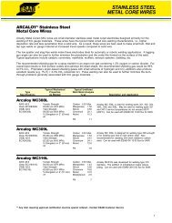
Figure 2. Brass, as well as mixed copper/aluminium joints,<br />
can be friction stir welded. © ESAB<br />
7108-T79 FSW 210 320 12 0.86<br />
7108-T79 FSW and aged 245 350 11 0.95 TWI<br />
7475- T76 FSW 381 465 12.8 0.92 Magnusson &<br />
Källman 2003<br />
7475- T76 Solution heattreated<br />
and aged<br />
Table 1. Collection of tensile test results for various aluminum alloys.<br />
Parameter<br />
Rotation speed<br />
Tilting angle<br />
<strong>Welding</strong> speed<br />
Down force<br />
Effects<br />
476 512 10 0.97 Magnusson &<br />
Källman 2004<br />
<strong>Friction</strong>al heat, “stirring”, oxide layer breaking and mixing of material.<br />
The appearance of the weld, thinning.<br />
Appearance, heat control.<br />
<strong>Friction</strong>al heat, maintaining contact conditions.<br />
Table 2. Main process parameters in friction stir welding.<br />
ideal for mechanised welding.<br />
Tools<br />
<strong>Welding</strong> tool design is critical<br />
in FSW. Optimising tool<br />
geometry to produce more<br />
heat or achieve more efficient<br />
“stirring” offers two main<br />
benefits: improved breaking<br />
and mixing of the oxide layer<br />
and more efficient heat<br />
generation, yielding higher<br />
welding speeds and, of course,<br />
Tensile strength is another important quality feature.<br />
Table 1 shows a collection of published results from tensile<br />
strength tests.<br />
Blue = base material Red = FSW Black = MIG<br />
Figure 3. Fatique life evaluation of AA5059.<br />
Alloy group Temperature range in °C<br />
Aluminium alloys 440…550<br />
Magnesium alloys 250…350<br />
Copper alloys 600…900<br />
Carbon and low-alloy steels 650…800<br />
Titanium alloys 700…950<br />
enhanced quality.<br />
The simplest tool can be<br />
machined from an M20 bolt<br />
with very little effort. It has<br />
proved feasible to weld thin<br />
aluminium plates, even with<br />
Table 3. <strong>Welding</strong> temperature range of various alloys.<br />
tooling as simple as this,<br />
6<br />
7
although at very slow welding speeds. However, tool<br />
materials should feature relatively high hardness at<br />
elevated temperatures, and should retain this<br />
hardness for an extended period. The combination<br />
of tool material and base material is therefore always<br />
crucial to the tool’s operational lifetime. Table 3<br />
illustrates the forging temperature range of different<br />
alloy groups. Note what useful tools forging tables<br />
are in the FSW context.<br />
Figure 4. Pin-tool geometries for FSW tools.<br />
Design principles<br />
The simple pin-shaped, non-profiled tool creates<br />
frictional heat and is very useful if enough downforce<br />
can be applied. Unfortunately, the oxide-layer<br />
breaking characteristics are not very good, and as<br />
material thickness is increased, welding heat at the<br />
lower part of the joint may be insufficient.<br />
With parameter adjustment and tool geometry<br />
optimisation, the oxide-layer could be broken more<br />
effectively. The need to generate more frictional heat<br />
and break the oxide-layer more effectively has been<br />
a driving force in tool development for light-metals.<br />
In Figure 4 different pin-tools are displayed showing<br />
differences in shape, size and geometric features, to<br />
match the needs of specific applications. Tool<br />
materials for mild and stainless steel have been<br />
added to the list. Figure 5 illustrates some standard<br />
tools trademarked by TWI (The <strong>Welding</strong> Institute).<br />
Triflute MX has proven to be a very capable<br />
multipurpose tool for welding all aluminium alloys.<br />
Tools for steels<br />
To apply FSW in steel or other high-temperature<br />
materials, the difficulty is mainly associated with<br />
finding proper tool material; a material that can<br />
withstand the high temperatures that are<br />
experienced during the process. Resistance to wear<br />
(durability) is one important aspect, especially as<br />
many of the intended applications are considered<br />
critical; hence there can be no traces of the tool left<br />
in the seam. One of the most promising tool<br />
materials so far is the so called PCBN<br />
Figure 5. Some of the basic tool shapes for friction stir welding.<br />
© TWI.<br />
(polycrystalline cubic boron nitride), which is<br />
manufactured by Mega<strong>Stir</strong> (Figure 6).<br />
Retractable pin tool<br />
The Retractable Pin Tool (RPT) or Adjustable Probe<br />
Tool is a machine feature in which the pin of the<br />
FSW tool may be moved independently of the tool’s<br />
shoulder. This permits adjustments of the pin length<br />
to be made during welding, to compensate for<br />
known material thickness variations or to close the<br />
exit hole of the weld.<br />
The advantages of RPT may be<br />
summarized as follows:<br />
• Ensures full root closure of the weld<br />
• Increases joint quality properties at the exit<br />
• Increases the joint’s aesthetic properties.<br />
This feature is available for the ESAB LEGIO and<br />
Super<strong>Stir</strong> units.<br />
Figure 6. Tools for welding steels. Tip material is polycrystalline cubic boron nitride (PCBN).<br />
8 9
Bobbin tool<br />
The bobbin tool employs a technique that enables<br />
Initiating a bobbin weld either involves first drilling a<br />
hole in the material in which the tool is inserted, or<br />
Yield strength R po,2<br />
Ultimate tensile strength, R m<br />
Hardness HV Elongation<br />
AA 6082 T6, AlSi1MgMn 260 MPa 310 MPa 95 9 % (A5)<br />
3. introduce FSW, which welds<br />
3-4 times faster than GMAW<br />
double-sided welding. The solution is a special<br />
designed tool, consisting of two shoulders, one on<br />
by employing a run-on preparation of the material.<br />
The end of the weld is normally welded through,<br />
Table 4. Mechanical properties of commercial alloy AA6082 T6.<br />
and generates signifi cant<br />
cost savings at a later phase<br />
each side of the workpiece to be joined. The two<br />
leaving the exit un-bounded, for removal at a later<br />
of the production process.<br />
elements of the tool are connected with the pin,<br />
which here runs through the material.<br />
stage.<br />
Tool:<br />
Forward movement (travel speed/tool rpm)<br />
Modified Tri-flute MX<br />
2.5 mm/rev<br />
Alternative number 3 is the<br />
The bobbin tool is typically used to join extruded<br />
Down force<br />
Sufficient<br />
most attractive, of course.<br />
Bobbin tool welding can be applied in several<br />
ways, but there are two main alternatives:<br />
profiles, where the technique eliminates the need for<br />
a backing bar or advanced fixtures.<br />
Preparation<br />
<strong>Welding</strong> speeds<br />
Table 5. <strong>Welding</strong> parameters.<br />
Degreasing with alcohol<br />
1.0 m/min, 3.0 m/min and 6.0 m/min<br />
A number of companies have<br />
chosen this alternative, for<br />
improved economy and<br />
• Fixed bobbin tool, in which the dis tance<br />
To summarize the advantages of bobbin tool<br />
increased production capacity.<br />
between the two shoulders is fixed.<br />
• Self-reacting bobbin tool, in which a retractable<br />
pin feature allows the distance between the two<br />
shoulders to be ad jus ted during the weld.<br />
There are, of course, benefits and drawbacks with<br />
both solutions. The first offers a simple mechanical<br />
welding, we find:<br />
• No backing bar needed.<br />
• Less complex fixtures.<br />
• No root flaws from incomplete penetration.<br />
• Less (or zero) down force needed.<br />
Process speed<br />
<strong>Welding</strong> speed Rp 0.2<br />
[Mpa] dev. R m<br />
[MPa] dev. Bend test [°.] A25 Dev.<br />
1 m/min 155.9 0.56 256.2 0.04 180 10.76 2.72<br />
3 m/min 171.1 1.71 268.5 0.24 180 11.46 0.75<br />
6 m/min 173.8 1.66 268.7 1.29 180 9.20 0.46<br />
Table 6. Summary of the test results on 5 mm AA6082 T6. The test results are based on an average<br />
of three tests (bending test only one sample).<br />
A Norwe gian shipyard has<br />
reduced production time for a<br />
60-m long catamaran hull from<br />
ten to six months, boosting<br />
capacity by 40%. This yielded<br />
cost savings of 10%, equivalent<br />
to 10% of total fabrication<br />
solution (for the welding head), as the tool differs in<br />
Not so long ago, one of the main “excuses” for not<br />
costs. These savings derive<br />
no way from a conventional FSW tool at the tool<br />
using FSW was the claim that its welding speed<br />
from three different<br />
interface. In contrast, the second allows us to<br />
was too slow for production, even though the<br />
improvements: 2% to 3% due<br />
control the contact conditions for the two shoulders<br />
mechanical properties of FSW welds outclass<br />
to improved extruded profile<br />
independently, to compensate for variations in<br />
conventional joining processes for alumi nium. The<br />
designs and the use of friction<br />
material thickness.<br />
typical stated welding speed for 5 mm AA6082 was<br />
stir welded panels,<br />
between 250 mm/min and 400 mm/min. This was<br />
4% to 5% due to improved<br />
typical for a CNC machine, not designed for the<br />
streamlined fabrication at the<br />
high down forces needed in FSW or the high travel<br />
yards and 3% due to new<br />
speeds. With production machines, welding speeds<br />
design (Midling, 2000).<br />
for the above-mentioned alloy are (and have been<br />
for a number of years) almost ten times higher –<br />
A series of test welds has been<br />
with 2000 mm/min a typical production speed when<br />
successfully conducted at the<br />
joining extruded profiles.<br />
ESAB <strong>Friction</strong> <strong>Stir</strong> Laboratory in<br />
Laxå Sweden, noting welding<br />
In a medium-size welding workshop (between 200<br />
and 400 blue-collar workers), time spent in welding<br />
Figure 8. Etched microstructure of AA6082 welded with inadequate ”heat input” in the root of the joint.<br />
speeds of up to 6 m/min on<br />
materials thicker than 1 mm.<br />
and related functions represents roughly 15% to<br />
The test results were achieved<br />
20% of total manu facturing time. This suggests three<br />
on 5 mm AA6082 alloy. The<br />
alternatives for improving productivity:<br />
mechanical properties of the base<br />
1. increase the welding speed of conventional<br />
material are presented in Table 4<br />
processes (GMAW, GTAW),<br />
and the test data in Table 5.<br />
2. introduce a new welding process that offers a<br />
Figure 7. Bobbin<br />
tool technique and<br />
weld cross-section.<br />
speed similar to conventional arc welding but that<br />
generates significant cost savings in other aspects<br />
of production, or<br />
10 11
As can be seen, the properties of<br />
the welds are fairly similar but,<br />
surprisingly, the mechanical<br />
properties are improved by some<br />
4-5% by welding faster (compare<br />
1 m/min. to 3 m/min.). As the<br />
welding speed is further increased,<br />
the mechanical properties<br />
remain excellent, although there<br />
is a slight deviation increase in<br />
tensile strength. This is mainly<br />
due to the reduced parameter<br />
box as speed is increased.<br />
Smaller and smaller variations in<br />
welding conditions may affect the<br />
quality more easily. Figure 8<br />
shows a typical welding fault<br />
experienced when welding<br />
outside the scope of the parameter<br />
box. The stirring was not<br />
good enough and has caused a<br />
fault on the root side of the weld.<br />
Since the heat input is further<br />
decreased as the welding speed<br />
is increased, there is a risk that<br />
welds can be “too cold”. Total<br />
control of welding parameters is<br />
essential to ensure a solid,<br />
defect-free weld at high speeds.<br />
From the hardness curves (Figure<br />
9), it can be seen that the curves<br />
for 1 and 6 m/min are almost<br />
identical. The curve for 3 m/min<br />
samples differs slightly, even<br />
though taken from the same<br />
batch. This is an excellent<br />
example of tolerance variation,<br />
which can sometimes exist even<br />
within the smallest batches. The<br />
joint hardness profile recorded for<br />
samples of unwelded base<br />
material welded at 1, 3 and 6 m/<br />
min was 112, 102 and 115HV<br />
respectively.<br />
Figure 9. Hardness profile across the weld joint at welding speeds<br />
of 1, 3 and 6 m/min. Base material: 5 mm AA6082.<br />
Fusion welding<br />
FSW<br />
1xxx<br />
Aluminium<br />
Cu Mn Si Mg Zn Other<br />
2xxx<br />
3xxx<br />
Heat-treatable<br />
Mostly weldable<br />
4xxx<br />
5xxx<br />
Figure 10. Weldability of various aluminium alloys. ©TWI<br />
6xxx<br />
7xxx<br />
Non-heat-treatable<br />
Mostly non-weldable<br />
8xxx<br />
Aluminium<br />
As an engineering alloy,<br />
aluminium has been competing<br />
with steel for several years<br />
now. It is approximately threetimes<br />
lighter and three-times<br />
“weaker” (elastic modulus 70<br />
GPa), with a thermal<br />
co-efficient three-times higher<br />
than steel (the rule of three<br />
threes). To avoid unnecessary<br />
reduction in strength, however,<br />
weight savings must often be<br />
compensated through<br />
improved design.<br />
High thermal conductivity<br />
combined with the protective<br />
oxide-layer of aluminium makes<br />
fusion (e.g. MIG) welding of this<br />
type of alloy difficult. The oxidelayer<br />
must be broken and<br />
removed and heat applied<br />
rapidly, to avoid unnecessary<br />
thermal expansion of the<br />
products. FSW avoids such<br />
problems.<br />
Table 7 through 9 feature a<br />
summary of a designation<br />
system for wrought and cast<br />
aluminium alloys, together with<br />
temper designations. These are<br />
commonly used designations in<br />
the aluminium business.<br />
12 13<br />
Alloy series<br />
1xxx<br />
2xxx<br />
3xxx<br />
4xxx<br />
5xxx<br />
6xxx<br />
7xxx<br />
8xxx<br />
9xxx<br />
Principal alloying element<br />
Aluminium, 99.00 % minimum or more<br />
Copper<br />
Manganese<br />
Silicon<br />
Magnesium<br />
Magnesium and silicon<br />
Zinc<br />
Other element<br />
Unused series<br />
Table 7. Designation system for wrought aluminium alloys.<br />
Alloy series<br />
1xx.x<br />
2xx.x<br />
3xx.x<br />
4xx.x<br />
5xx.x<br />
6xx.x<br />
7xx.x<br />
8xx.x<br />
9xx.x<br />
Principal alloying element<br />
Essentially pure aluminium<br />
Copper<br />
Silicon + Copper and/or magnesium<br />
Silicon<br />
Magnesium<br />
Unused series<br />
zinc<br />
Tin<br />
Other element<br />
Table 8. Designation system for cast aluminium alloys.<br />
Temper designations<br />
"F" "as fabricated"<br />
No special control of thermal or<br />
strain-hardening conditions.<br />
"0" "annealed"<br />
Applies to wrought and cast products<br />
which have been heated to produce the<br />
lowest strength condition and to improve<br />
ductility and dimensional stability.<br />
“H" "strain hardened"<br />
Strengthened by strain-hardening<br />
through cold-working.<br />
The first digit indicates basic operations:<br />
H1 - strain hardened only<br />
H2 - strain hardened and partially<br />
annealed<br />
H3 - strain hardened and stabilised<br />
The second digit indicates degree of<br />
strain hardening<br />
HX2 - 1/4 hard<br />
HX4 - 1/2 hard<br />
HX6 - 3/4 hard<br />
HX8 - hard<br />
HX9 - extra hard<br />
"W" ”solution heat-treated”<br />
Applicable only to alloys which age<br />
spontaneously at room temperature<br />
after solution heat-treatment. Solution<br />
heat-treatment involves heating the<br />
alloy to approximately 538 °C (1000 °F)<br />
to transform the alloying elements into<br />
a solid solution, followed by rapid<br />
quenching to achieve a super-saturated<br />
solution at room temperature.<br />
"T" 'thermally treated to produce stable<br />
tempers other than F, O or H'<br />
Applies to products, which have been<br />
heat-treated. The first digit indicates<br />
specific sequence of treatments:<br />
T1 - naturally aged after cooling from an<br />
elevated-temperature shaping process,<br />
such as extruding.<br />
T2 - cold worked after cooling from an<br />
elevated-temperature shaping process<br />
and then naturally aged.<br />
T3 - solution heat-treated, cold worked<br />
and naturally aged.<br />
T4 - solution heat-treated and naturally aged<br />
T5 - artificially aged after cooling from<br />
an elevated-temperature shaping<br />
process<br />
T6 - solution heat-treated and artificially aged<br />
T7 - solution heat-treated and stabilised<br />
(overaged)<br />
T8 - solution heat-treated, cold worked<br />
and artificially aged<br />
T9 - solution heat-treated, artificially<br />
aged and cold worked<br />
T10 - cold worked after cooling from an<br />
elevated-temperature shaping process<br />
and then artificially aged.<br />
The second digit indicates variation<br />
in basic treatment.<br />
Additional digits indicate stress relief.<br />
TX51 - Stress relieved by stretching<br />
TX52 - Stress relieved by compressing
Application areas<br />
Figure 12. Longitudinal welding machines for joining of machined isogrids,<br />
vertically and horizontally. Previously, these segments were joined using<br />
MIG or VPPAW (Variable Polarity Plasma-Arc <strong>Welding</strong>) technology.<br />
Aerospace<br />
Figure 11. Nobel Peace Centre, Oslo Norway. The canopy is a temporary installation by David Adjaye that serves as a gateway between<br />
Oslo City Hall where the Peace Prize Ceremony takes place and the Nobel Peace Center. The canopy has been manufactured<br />
with the FSW process. Photo: Timothy Soar / Adjaye Associates.<br />
Sector Main Applications Substitutes<br />
Electrical Busbars Copper<br />
Transformers and generators<br />
Copper<br />
Transportation:<br />
Automobiles See Table 10 Copper / brass<br />
Aerospace Structural components Steel/Plastic/Magnesium<br />
Commercial airframes<br />
Carbon reinforced and other composite materials<br />
Rolling stock Freight cars Steel<br />
Coaches<br />
Steel<br />
Marine Boat hulls Timber, fiberglass, coated steel,<br />
Propellers<br />
brass, stainless steel<br />
Consumer durables Refrigerators and freezers Steel, plastics<br />
Air conditioners<br />
Copper<br />
Construction Cladding Timber, coated steel, plastic<br />
Roofing<br />
Timber, galvanised steel, lead<br />
Window and door frames<br />
Timber, PVC<br />
Fencing<br />
Timber, concrete, steel<br />
Industrial Heat exchangers Copper, stainless steel<br />
Hydraulic systems<br />
Steel<br />
Machinery and equipment Irrigation piping Cast iron, steel, plastic<br />
Table 9. General application areas of aluminium and some of its substitutes.<br />
Space industry<br />
<strong>Friction</strong> stir welding was first introduced to a larger,<br />
general public at the Schweissen & Schneiden Fair<br />
in 1997. The equipment displayed is shown in<br />
Figure 13. It was later purchased by The Boeing<br />
Company for research and laboratory use. Besides<br />
the laboratory machine, Boeing has been a real<br />
pioneer in introducing FSW into industrial<br />
manufacturing. In the Delta II and IV programs,<br />
FSW has been widely adopted and used for<br />
manufacturing rocket-fuel tanks, Figure 12.<br />
Production time for a typical tank has been<br />
dramatically reduced and a number of cost savings<br />
have been achieved. At about 20% of the cost of<br />
riveting, FSW offers surprisingly significant cost<br />
gains. Not just at the Boeing Company, but almost<br />
anywhere aerospace or civil aviation equipment is<br />
being manufactured, FSW production technology is<br />
being considered for future designs. A number of<br />
different applications in the commercial and military<br />
aircraft industry are under evaluation, including<br />
carrier beams, floors and complete fuselages and<br />
wings (Eriksson, 2001).<br />
Figure 13. Super<strong>Stir</strong> #1 - first friction stir welding machine introduced to<br />
gene ral public 1997 at the Schweissen & Schneiden Fair. Currently used at<br />
Boeing laboratories for research and development work.<br />
Figure 14. Circumferential welding machine, featuring Bobbin<br />
Tool and Plug <strong>Welding</strong> technology.<br />
14 15
Civil aviation<br />
The main rationale for employing FSW (or welding in<br />
general, for that matter) in the manufacture of aerospace<br />
components is weight savings, which translate directly<br />
into cost savings. Reducing weight enables higher<br />
speeds and/or reduced fuel consumption.<br />
<strong>Friction</strong> <strong>Stir</strong> <strong>Welding</strong> not only eliminates rivets and<br />
fasteners, but the need for an overlap sheet<br />
configuration. The butt-joint configuration also facilitates<br />
joint evaluation and quality assurance, because a<br />
homogeneous joint with full penetration eliminates<br />
crack formation.<br />
joining process for aircraft, signifies a major breakthrough<br />
in the field of civil aviation. The Eclipse 500 businessclass<br />
jet is one example where FSW is used in the<br />
production of civil aircraft.<br />
Aerospace R&D<br />
Many may believe that the traditional metals for airframe<br />
structures are being pushed aside by the recent<br />
advances in composites. Major breakthroughs have<br />
certainly been achieved in these alternative materials, but<br />
important ongoing R&D, in which FSW plays a vital role,<br />
continues. Several such R&D programmes are funded by<br />
the European Commission.<br />
The fact that FSW offers the means to join previously<br />
unweldable Al-Li (e.g. AA2195) alloys has attracted<br />
growing interest from the civil aeronautics and aerospace<br />
industries. High strength and low weight is always<br />
a desirable combination. When allied to a robust welding<br />
method, this opens a whole new field of possibilities.<br />
Approval by the FAA (Federal Aviation Association),<br />
which has certified the friction stir welding process as a<br />
The great mechanical properties of FSW have always<br />
been the key justification for adopting the process.<br />
Research, driven primarily by the aerospace industry,<br />
has shown that post-weld ageing treatments can even<br />
improve these properties. In one example, material<br />
welded according to T4 status (heat-treatment), then<br />
aged to T6 status, regained 100% of the parent<br />
material’s ultimate tensile strength.<br />
The maturity of the technique has led to broader acceptance<br />
within companies such as EADS and Boeing,<br />
where FSW is now a qualified and certified process.<br />
Numerous applications are being considered, for both<br />
thin and thick sections of aluminium. Given its elimination<br />
of the need for fasteners, the future looks bright for<br />
ongoing development of FSW in the aerospace industry.<br />
A good manufacturing unit is the basis for research work.<br />
There is no use in creating excellent test values in the<br />
laboratory if the parameters and conditions cannot be<br />
transferred to production. Recognizing this, some of the<br />
leading European aerospace research units have<br />
purchased production-capable units for their R&D<br />
purposes.<br />
Figure 15. Research and prototype manufacturing units<br />
at EADS in association with L’Institute d’Soudure in France,<br />
Alenia Spazio in Italy and EADS Ottobrunn in Germany.<br />
16 17
Shipbuilding<br />
Parts and components<br />
issue to consider: the resulting reflections are<br />
One of the most attractive features of friction<br />
also important. A lot of time is spent polishing<br />
Application advances<br />
stir welded products is that they are ready-to-<br />
and ”making-up” surfaces, that are<br />
Imagine a large catamaran that can be constructed from<br />
use. Normally, time consuming post-weld<br />
architecturally visible. In FSW prefabricated<br />
building blocks, just like a toy boat. All the pieces would fit<br />
treatment such as grinding, polishing or<br />
panels, the reflections derive merely from the<br />
perfectly together, ensuring mastery of dimensional accuracy<br />
straightening is not needed. With proper<br />
surface appearance of the aluminium plates<br />
and simplifying any necessary modifications. FSW represents<br />
design, the elements are ready-to-use directly<br />
and profiles in the as-delivered state, not from<br />
a first step towards this type of construction approach in<br />
after welding. However, it is important to keep<br />
the reflections caused by welding heat input.<br />
shipbuilding.<br />
in mind that designs intended for MIG or TIG<br />
One of the earliest examples of a product<br />
welding are not necessarily suitable for FSW.<br />
where FSW was extensively used is shown<br />
The low heat input during joining assures less residual stress,<br />
A fillet-joint geometry, often applied with MIG,<br />
in Figure 19 – Catamaran made by<br />
resulting in precisely welded components that require minimal<br />
may not be suitable for FSW, for which T-joint<br />
Fjellstrand AS, using extruded and FS<br />
fit-up work. The resulting savings, both in time and money, are<br />
geometry is much more suitable (Figure 16).<br />
welded profiles, produced by Marine<br />
obvious. This offers users of FSW pre-fabricates a clear<br />
Aluminium AS.<br />
competitive advantage, although documented data on actual<br />
One limiting factor, often mentioned when<br />
savings is seldom reported. However, the following gives an<br />
discussing FSW, is the relatively high down-<br />
One excuse for not using aluminium has<br />
idea of how panel producers (Midling) can benefit from the<br />
force needed when performing the weld. One<br />
always been ”it’s not as strong as steel.” True<br />
production of friction stir welded pre-fabricated panels:<br />
issue is the machine’s capacity to apply such<br />
– and not true. It depends on the alloy used,<br />
• Industrial production featuring a high degree of<br />
completion.<br />
• Extended level of repeatability, ensuring uniform level of<br />
performance, quality and narrow tolerances.<br />
a high force, another is its ability to support<br />
and firmly clamp the workpiece. With a<br />
traditional butt-joint a backing bar supports<br />
the root side of the joint. The surface finish<br />
of course, and surprisingly there are aluminium<br />
alloys that are as strong or even stronger than<br />
steel. ”ALUSTAR”, for example, has yield and<br />
tensile strengths comparable to S235 low-<br />
Figure 18. Flat panel field after welding.<br />
Instead of using wide profiles,<br />
the panel is made from relatively<br />
narrow (120 mm) extrusions. ©ESAB<br />
• The flexible production equipment and capacity permits<br />
should be of high quality, as the aesthetic<br />
alloyed steel . AlCu4SiMg (AA2014) – an alloy<br />
customized solutions without compromising delivery<br />
properties of the root side of the joint will<br />
typically used in aerospace applications – is<br />
Figure 16. A traditional fillet joint versus FSW T-joint geometry.<br />
reliability.<br />
• The completed panel units have been inspected and<br />
follow the backing bar.<br />
significantly stronger than alloys in the 5xxx<br />
and 6xxx series, typically used in shipbuilding.<br />
approved by classification authorities such as DNV, RINA<br />
Another solution to the fixture issue is to<br />
Some of these alloys have never been used in<br />
and Lloyd’s Register.<br />
modify to an ’FSW-friendly’design, eliminating<br />
shipbuilding, because of their poor weldability!<br />
• The panels’ high degree of straightness ensures easy<br />
the need for a backing bar. One application<br />
With friction stir welding, some of these<br />
assembly at the yard, reducing the need for manual<br />
where such an approach is appropriate is in<br />
barriers can be overcome. Imagine using the<br />
welding.<br />
the manufacture of extruded profiles<br />
strong AA7021 alloy for making aluminium<br />
• Less supplementary work for the customer, such as floor<br />
(Figure 17).<br />
floor panels even thinner, generating weight<br />
levelling and preparation for floor coverings, offering major<br />
cost savings.<br />
When producing large components, like walls<br />
or floors, panel straightness is not the only<br />
savings by ”thinking differently”.<br />
Figure 19. The first vessel in world<br />
history made from FS-panels was<br />
built by Fjellstrand AS in 1996.<br />
The panels were made by Marine<br />
Aluminium. This was what actually<br />
kick-started the industrialisation of<br />
the process.<br />
Figure 17. Designs which make it possible to weld hollow profiles.<br />
18 19
Automotive industry<br />
The automotive industry, featuring large manufacturing batches,<br />
six sigma requirements and challenging material combinations,<br />
from wrought and cast aluminium to magnesium alloys, provides<br />
a perfect field for FSW applications. One good example is<br />
illustrated in Figure 22, which shows a fully automated ESAB<br />
Super<strong>Stir</strong> machine for the welding of seat frames at SAPA,<br />
Sweden. The cycle time is less than one minute per seat, using<br />
dual welding heads.<br />
<strong>Welding</strong> speed depends on the alloy to be welded and tool<br />
geometry. However, speeds up to 6 metres/minute on 5 mm<br />
AA6082 are possible. The alloys, which are sensitive to heat,<br />
actually tend to demonstrate better mechanical properties when<br />
Figure 22. Fully automatic manufacturing cell for production<br />
of car components. ©SAPA, Sweden.<br />
welded rapidly, since changes in the chemical composition of<br />
the material are avoided. Alloys which are difficult to join using<br />
conventional arc-welding processes can often be joined by FSW.<br />
This offers numerous possibilities, as in the construction of<br />
military vehicles.<br />
In Figure 10, the weldability of various aluminium alloys is shown<br />
Overlap and butt joints can be welded in all positions, as well as<br />
as a reminder. The typical alloys used in shipbuilding are from<br />
mixed welds (different thicknesses or different materials – the<br />
the 5xxx series, due to their good corrosion resistance, or from<br />
5000 to 6000 series, for example). Even cast aluminium<br />
the 6xxx series, due to their strength. Other combinations of<br />
components are easily welded. The microstructure and<br />
these two alloys are also possible, of course (Larsson et al.<br />
homogeneity of the cast material improves significantly when FS<br />
2000).<br />
welded. The porosity that is typically present in castings<br />
disappears. Figure 23 shows an etched surface on a T-joint<br />
Figure 20. FSW LEGIO 3UT installed next to the<br />
aluminium ship hull production line at Estaleiros Navais<br />
do Mondego S.A. shipyard in Portugal, 2002.<br />
Figure 20 gives an idea of relatively easy implementation of FSW<br />
in shipbuilding. ESAB’s new LEGIO concept is ideal for<br />
fabrication of small batches of friction stir welded panels. The<br />
equipment is placed in the workshop right next to the assembly<br />
of the ship’s hull. The picture is from Estaleiros Navais do<br />
Figure 23. Etched microstructure on cast aluminium T-joint<br />
shows that the weld area has fine-grained microstructure<br />
without porosity. The fine “crack-shaped-line” coming from<br />
the right indicates a poorly stirred oxide-layer, not a crack.<br />
between two cast plates. The microstructure of the stir-zone is<br />
much finer-grained than the relatively coarse cast plate material,<br />
which is typical with FSW.<br />
Joining components of different thicknesses or dissimilar alloys is<br />
Mondego S.A. Shipyard in Portugal. Even small batches can be<br />
a very demanding task when utilising arc or beam welding<br />
effectively welded on-site.<br />
processes. With FSW, plates of different thicknesses can be<br />
joined securely with a high quality weld (Figure 24.) Overlap joints<br />
are also possible with FSW, providing an alternative solution to<br />
resistance-spot-welded or seam-welded pieces. An excellent<br />
alternative to spot-welding to achieve a watertight seal may be<br />
seen in Figure 24.<br />
Figure 21. Modular LEGIO 5UT friction stir welding machine<br />
for flexible manufacturing. The working envelope of this<br />
particular equipment is 6000x500x300mm (x-, y-, z- axis).<br />
Delivered to KMT–tekniikka OY, Finland, December 2003.<br />
Figure 24. Possible automotive applications for friction stir welding:<br />
mixed joint between two thickness (1+2 mm), overlap joint on 1 mm<br />
thickness and folded seal weld. ©ESAB.<br />
20<br />
21
Figure 25. A car features countless application areas for aluminium, as can be seen<br />
in this picture taken at the Aluminium 2002 Fair in Germany, at the SAPA stand.<br />
Automotive applications<br />
In principle, all aluminium components in a car can be friction stir<br />
welded: bumper beams, rear spoilers, crash boxes, alloy wheels, air<br />
suspension systems, rear axles, drive shafts, intake manifolds,<br />
stiffening frames, water coolers, engine blocks, cylinder heads,<br />
dashboards, roll-over beams, pistons, etc. Minor modifications to the<br />
structure may be needed in order to make it more suitable for FSW,<br />
but these should not be insurmountable.<br />
In larger road transport vehic les, the scope for applications is even<br />
wider and easier to adapt – long, straight or curved welds: trailer<br />
beams, cabins and doors, spoilers, front walls, closed body or<br />
curtains, dropside walls, frames, rear doors and tail lifts, floors, sides,<br />
front and rear bumpers, chassis (Figure 25), fuel and air con tainers,<br />
tool boxes, wheels, engine parts, etc.<br />
Inner and outer body panels 2008, 2010, 2036, 3004, 5052, 5182, 5754, 6009, 6010, 6016, 6022, 6111<br />
General structural components 6005, 6005A, 6009, 6061<br />
extrusions 6063, 6082, 7005<br />
luggage racks, air deflections 6463<br />
space tire carrier parts 6061<br />
Bumper components<br />
ace bars 5052, 6009<br />
reinforcements 6009, 6061, 7003, 7004, 7021, 7029<br />
brackets 6009, 7021<br />
Seats<br />
shells 7036, 6010<br />
headrest bars 7116, 7129<br />
tracks 6010, 5182, 5754, 6009<br />
Load floors 2036, 5182, 5754, 6009<br />
Wheels 5454, 6061, A356.0<br />
Suspension parts<br />
6061 (forging)<br />
Drive shaft<br />
6061 (tube), aluminium metal matrix alloys<br />
Drive shaft yokes<br />
6061 (forgings and impact extrusions)<br />
Engine accessory brackets and mounts 5454, 5754<br />
Sub-frames and engine cradles 5454, 5754, 6061, 6063<br />
Miscellaneous<br />
Radiator tubes; heater cores; radiators, 3003<br />
heater and evaporator fins; oil coolers;<br />
heaters and air conditioner tubes<br />
Radiator, heater and evaporator fins 3005<br />
Condenser tubes 3102<br />
Condenser and radiator fins 7072<br />
Table 10. Aluminium alloys typical for the automotive industry and its respective application areas (Irving 2000).<br />
Figure 27. A longitudinal FSW weld in<br />
a rectangular profile. Beams can be<br />
manufactured with minimal distortion.<br />
The machine is equipped with<br />
two separate welding heads for<br />
simultaneous welding from top<br />
and bottom, to ensure<br />
symmetric heat distribution and<br />
avoid “root” problems. As the<br />
heat is generated on both<br />
sides, this is the fastest and<br />
most effective way to use FSW.<br />
The time-consuming plunging<br />
operation (penetration of the<br />
material) is halved (half the<br />
plate thickness), with heat<br />
generated on both sides.<br />
Tower lists the benefits of FSW<br />
as follows:<br />
• reduced weight – estimated<br />
40% vs. GMAW<br />
• improved joint efficiency<br />
(2x tensile strength of GMAW<br />
in 6000 series aluminium)<br />
• increased fatigue life (2x to<br />
20x GMAW)<br />
• no consumables (no filler<br />
wire or shielding gas<br />
required)<br />
• less distortion – low heat<br />
input<br />
• improved energy efficiency<br />
• environmentally friendly – no<br />
fumes or spatter.<br />
The ESAB Super<strong>Stir</strong> unit shown in Figure 26 was delivered to<br />
Tower Automotive in 2000. The machine is designed for making a<br />
large profile from two or three extrusions. The welded profile is then<br />
cut into smaller widths to form a lightweight suspension link.<br />
Figure 26. ESAB Super<strong>Stir</strong><br />
unit at Tower automotive.<br />
Figure 28. Suspension links by Tower Automotive.<br />
22<br />
23
Figure 29. A butt and overlap weld of<br />
circular canister.<br />
Another application for suspension components<br />
is a three-piece suspension arm on<br />
the BMW 5-series (Sato et. al, 1998). In their<br />
case study, they have been able to improve<br />
the properties of the suspension arm. Some<br />
of the main areas of interest for such a component<br />
are of course weight, and road noise<br />
reduction capabilities. In this particular application,<br />
it was noticed that the heat imparted<br />
to the ball joint portion during welding did not<br />
exceed 120°C, leaving the rubber bellows<br />
attached to this component unaffected.<br />
<strong>Welding</strong> aluminium wheels was one of the<br />
earliest automotive applications for FSW.<br />
FSW was first used for longitudinal welding of<br />
aluminium tube, which was later cut to the<br />
proper length and spin-formed to the right<br />
shape. Hydro in Norway has used FSW in<br />
attaching the inner rim to the wheel form<br />
(Figure 29). The butt and overlap welds can<br />
be fabricated in wrought and/or cast<br />
materials (Johnson et al. 1999).<br />
Cast aluminium components can successfully<br />
be friction stir welded or processed to improve<br />
the quality of the cast structure, or to join<br />
inserts in the piston. In <strong>Friction</strong> <strong>Stir</strong><br />
Processing there is no “weld joint”, but the<br />
tool travels on the material and stirs it and<br />
results in fine-grained microstructure, and the<br />
porosity typical to castings will vanish. The<br />
amount of potential applications in the<br />
engine of any motor ve hic le alone is<br />
incredible, not to mention the cast or forged<br />
components used in load-carrying<br />
applications. An example of imp roved<br />
product quality is shown in Figure 30.<br />
More and more aluminium is used in<br />
transport vehicles to lower “dead load” and<br />
increase payload. The ever increasing<br />
awareness of environmental issues has also<br />
placed pressure on weight reduction in many<br />
road applications. A lorry offers countless<br />
potential applications for FSW – mainly<br />
straight linear welds in the x-y plane, with<br />
easily weldable materials and thicknesses<br />
typically of up to 5 mm. Replacing conventional<br />
arc welding joining processes with<br />
FSW can lead to a dramatic improvement in<br />
panel straightness and reduce assembly<br />
times to a minimum.<br />
Figure 30. A friction stir processed piston.<br />
The metallographic structure was clearly<br />
improved after friction stir processing.<br />
Tower on the press (Aluminum Now, 2003):<br />
Ford suspension link the first US auto part<br />
to be friction stir welded<br />
Tower Automotive has successfully produced<br />
aluminum suspension links for the Ford Motor<br />
Company using the friction stir welding process.<br />
It is the first time in the US that friction stir<br />
welding has been used in the manufacture of an<br />
automotive component.<br />
Recognizing the potential for applying friction<br />
stir welding to automotive applications, Tower<br />
purchased a license from TWI to carry out<br />
testing of the process. These tests showed<br />
that, compared to the traditional automotive<br />
industry method of gas metal arc welding, friction<br />
stir welding could reduce weight, lower costs,<br />
increase joint efficiency and increase fatigue life.<br />
”This new process offers superior joining<br />
technology in all aluminum series,” says Art<br />
Scafe, Tower’s product development manager<br />
for suspension components. ”The quality level<br />
created by a friction stir weld is superior to other<br />
types of welding.”<br />
Tower Automotive worked with Ford to develop<br />
the friction stir welded design for the suspension<br />
links in the company’s line of Lincoln Town Car<br />
limousines. According to Scafe, friction stir<br />
welding was used to join half-inch-thick pieces of<br />
6061 aluminum.<br />
Within six months, Tower completed the<br />
suspension link design, analysis, welding<br />
specifications, prototyping and product testing.<br />
The first vehicles with the friction stir welded<br />
suspension links rolled off the assembly line at<br />
Ford’s Wixom, Mich., plant in October 2002.<br />
According to Tower spokesman Kevin Kennedy,<br />
the company is looking at additional nonsuspension<br />
applications in which to apply friction<br />
stir welding, including aluminum body panels.<br />
”Use of friction stir welding is design-dependent<br />
and material-dependent. The process works best<br />
with a straight, flat surface to weld.”<br />
24
AA 5754 H22 Yield strength Tensile strength Elongation<br />
1.0 mm plate: R p0,2<br />
= 130 N/mm 2 R m<br />
= 248 N/mm 2 A 50mm<br />
=18%<br />
2.0 mm plate R p0,2<br />
= 122 N/mm 2 R m<br />
= 227 N/mm 2 A 50mm<br />
=17%<br />
No porosity! No undercut or lack of penetration!<br />
Table 11. Mechanical properties of the plates shown on Figure 31. © ESAB<br />
Figure 31. Tailor-welded blank on AA5754 H22, employing thicknesses 1 and<br />
2 mm. <strong>Welding</strong> was carried out using a fixture featuring an inclined table at a<br />
speed of 6 m/min. © ESAB<br />
Tailor welded blanks (TWB’s)<br />
Combining different alloys and/<br />
or different thicknesses<br />
represents one of the most<br />
interesting areas in automotive<br />
joining applications. Laser and<br />
laser-hybrid welding have<br />
achieved a relatively<br />
unchallenged predominance in<br />
the joining of steels and<br />
stainless steels, but FSW offers<br />
considerable potential for<br />
aluminium joining.<br />
Superplastic forming<br />
The next step in exploitation of<br />
FSW as a welding process will<br />
be in superplastically-formed<br />
products, as already<br />
demonstrated by Aston Martin<br />
in their Vanguard model. This<br />
technique often goes hand in<br />
hand with the manufacturing of<br />
tailor-welded blanks, and some<br />
applications are already<br />
available for manufacturing door<br />
components. In superplastic<br />
forming, pressurised gas is<br />
employed to impart the<br />
product’s final shapes.<br />
Connecting welds are sited in<br />
relatively simple positions, using<br />
simple plate shapes. When gas<br />
pressure is applied, the final<br />
shape of the structure is<br />
formed.<br />
Figure 32. Machined heat zinc for electrical components to be used for e.g. automotive applications.<br />
26<br />
27
Figure 33. Typical extrusion widths for open, half-open and hollow<br />
profiles.<br />
Extruders and extrusions – with special<br />
focus on rolling-stock-type panels<br />
<strong>Welding</strong> of two or more narrow extrusions to create a single<br />
broader extrusion is a classic FSW application. The first<br />
industrial-scale equipment to utilise this concept in full was<br />
delivered to Marine Aluminium, Norway, in 1996. The equipment<br />
has been in constant use ever since and has produced<br />
hundreds of thousands of metres of defect-free welds.<br />
Maximum and minimum size limits apply to the various<br />
extrusions, according to their hollow profile (open, half-open or<br />
closed). This poses challenges concerning the optimal balance,<br />
technically and economically. Conglin Aluminum Corp in China<br />
has a 10.000 MT press capable of manufacturing extrusions up<br />
to 970 mm in width. These extrusions are used in constructing<br />
the Levitation Train scheduled for service between Shanghai<br />
Airport and the city of Shanghai (Aluminium Extrusion, 2002).<br />
Plants capable of this size of extrusion are very rare. The more<br />
typical widths for commercially available extrusions are shown in<br />
Figure 33.<br />
Figure 34. Fully automatic panel welding equipment at SAPA,<br />
Sweden. The equipment features three welding heads – two on the<br />
upper side, one on the lower side.<br />
Figure 35. An extruded profile designed for friction stir welding.<br />
To achieve high productivity in joining profiles requires a “gentle<br />
giant”, powerful and robust equipment that ensures extremely<br />
accurate control of the welding forces and position of the tool.<br />
Multiple welding heads also promote increased productivity and<br />
reduced cycle times. Figure 34 shows fully-automatic welding<br />
equipment with two welding heads on the upper side and one<br />
welding head on the lower side. The two upper heads are used<br />
on single skins to almost double welding capacity, starting from<br />
the middle and welding outwards, upper and lower heads being<br />
used to weld both sides of a double skin panel. The welding<br />
length of 14.5 metres enables the production of very large<br />
components used in the manufacture items such as rolling stock<br />
and heavy goods vehicles.<br />
To weld extrusions into wider plates or join hollow-profiles, the<br />
design of the profiles must be adapted to the requirements of<br />
the friction stir welding process. The main criterion is the ability<br />
to withstand the welding forces without suffering collapse or<br />
buckling. A profile designed for the GMAW process can be<br />
welded much more easily when adapting for FSW.<br />
Figure 36. Shinkansen train. <strong>Friction</strong> stir welding is employed for the floor panels.<br />
Manufacturers of rolling stock (rail cars and train carriages) are extremely<br />
keen to use FSW to manufacture a range of components. Alstom LHB,<br />
for example, has used FS welded floor and wall panels supplied by<br />
Hydro Marine, Norway, since 2001, in the construction of its suburban<br />
trains (Kallee et al. 2002). Hitachi of Japan, another train-industry pioneer,<br />
has used friction stir pre-fabricated floor elements for its Shinkansen<br />
trains (Figure 36). Here too, the profiles and extrusions must be designed<br />
for FSW. An example of an FSW profile design is shown in Figure 35.<br />
The thickness of the weld area, as well as the radii on the corners,<br />
demonstrate the know-how that some extruders have started to<br />
accumulate, even if they do not friction stir weld themselves. The<br />
extrusion market offers clear opportunities for future business.<br />
Figure 37 shows a quality inspection being performed on panels welded<br />
using large panel machines featuring simultaneous welding with one<br />
upper and one lower head. The flatness is incredible!<br />
Figure 37. Perfectly flat hollow profiles<br />
inspec ted after welding at SAPA, Sweden.<br />
28<br />
29
Steel and other High<br />
Temperature Materials (HTM)<br />
Introduction - Weld characteristics of High Temperature<br />
Materials (HTM) FSW<br />
The weld quality of steels exposed to FSW is much the<br />
same as that of aluminium. Both involve a solid-state joining<br />
process that produces a fine grain microstructure and,<br />
because of the low heat input, the HAZ shows less<br />
degradation.<br />
Steels that are considered unweldable can be joined with full<br />
penetration in a single pass. They are a bit more complicated<br />
than aluminium, as the phase transformations can be<br />
complex. Different metallurgical properties can be achieved<br />
by varying the process. When applied to an HTM alloy, the<br />
FSW process will also require a liquid-cooled tool holder and<br />
the addition of a shielding gas (Ar).<br />
The variables that govern the FSW process are temperature,<br />
load, tool travel speed, spindle RPM, tool design, tool<br />
thermal conductivity, material flow stresses, material thermal<br />
conductivity, the melting point of the material and the heat<br />
transfer characteristics of the system. Aluminium alloys can<br />
be friction stir welded using a broad range of process<br />
parameters because of their low strength, high ductility and<br />
high thermal conductivity. Successful FSW of ferrous, nickel<br />
base and other high melting temperature alloys requires<br />
careful control of the process variables discussed above.<br />
Weldable materials<br />
A number of high melting temperature alloys have been<br />
successfully joined using FSW. Many other applications are<br />
still to be explored. Alloys already successfully joined using<br />
FSW include:<br />
1. Carbon steels, including high strength steels, pipe steels,<br />
and Dual-Phased/TRIP steels<br />
2. Stainless steels, including Super Duplex, Super Chrome<br />
and Ferritic. These alloys exhibit a refined grain structure<br />
in the weld zone. <strong>Friction</strong> <strong>Stir</strong> <strong>Welding</strong> of these alloys<br />
offers numerous benefits, such as<br />
• Critical Pitting Temperature (CPT) is 20º C higher<br />
than arc-welding processes<br />
• FSW does not introduce harmful intermetallics<br />
• FSW retains the proper ratio of austenite and ferrite<br />
• FSW does not form excessive amounts of martensite<br />
• FSW creates a matching fusion zone without<br />
reinforcement<br />
3. Ni-based alloys<br />
4. Other non-weldable alloys.<br />
System components for HTM FSW<br />
To weld high temperature materials such as ferrous, nickel<br />
base and titanium alloys is merely a question of finding the<br />
proper tool materials that can withstand the high<br />
temperatures (approx. 1200° C) and high forces<br />
experienced during welding in all axes (Z and X- or Y-axis).<br />
The tool must also be designed to produce consistent weld<br />
properties and maintain high abrasion resistance<br />
Polycrystalline Cubic Boron Nitride (PCBN) is used for the<br />
tip of the tool because of its thermal stability, hardness and<br />
strength at elevated temperatures. PCBN is classified as a<br />
super-abrasive material and is fabricated in a two-step ultra<br />
high temperature/high pressure (UHT/HP) process. CBN is<br />
the second hardest known material and its synthesis<br />
mimics the graphite to diamond conversion process.<br />
PCBN’s low coefficient of friction minimizes material<br />
adhesion to the tool surface during FSW and reduces<br />
spindle horsepower requirements. The high thermal<br />
conductivity of PCBN reduces temperature gradients within<br />
the tip and helps minimize temperature gradients and<br />
residual stresses in the base metal being welded. The high<br />
hardness values of PCBN limit tool abrasion during the<br />
FSW process. Fracture toughness values of PCBN are low<br />
relative to metals but the polycrystalline nature prevents<br />
cleavage planes and minimizes crack initiation sites. An<br />
insulating material is used between the PCBN tip and the<br />
tungsten carbide shank to maintain the proper amount of<br />
heat at the tip.<br />
Thermocouple<br />
Shroud for<br />
Shielding Gas<br />
Figure 38. HMT FSW Pin Tool and Weld Head assembly.<br />
Shielding<br />
Gas Inlet<br />
Figure 39. Orbital friction stir welding of steel pipe.<br />
In addition to the HTM FSW tool, a patented temperature<br />
control assembly has been designed to function with any<br />
rigid load control machine to friction stir weld HTM alloys.<br />
Two additional components make up this system including a<br />
liquid-cooled tool holder, and a telemetry system consisting<br />
of a transmitting or telemetry collar and loop antenna.<br />
The liquid-cooled tool holder manages heat removal from the<br />
FSW tool and protects the machine spindle bearings. The<br />
telemetry system is a wireless temperature acquisition<br />
system required for continuous real time temperature data<br />
control, thereby prolonging tool life and indirectly managing<br />
the target material temperature.<br />
Applications<br />
Potential winning applications include:<br />
Oil and gas - With the development of portable equipment<br />
specific to FSW, orbital welding can now perform girth welds<br />
for land and offshore pipelines in the field. This further<br />
enables this useful technology to be applied for pipe welding<br />
where welding repair and direct costs are high. From a<br />
mechanical capability standpoint, FSW welding of up to 1/2<br />
inch (12.7mm) maximum on X65 - X100 steels is highly<br />
repeatable and development is currently underway to<br />
expand this capability for X120 up to 3/4 inch (19 mm). For<br />
the pipeline industry in particular, FSW is advantageous<br />
because, compared to conventional fusion welding<br />
processes such as arc and laser welding, FSW is highly<br />
energy efficient, with reduction in energy usage by 60 to 80%<br />
not uncommon. FSW offers better weld quality because it is<br />
immune to the welding defects caused by solidification in<br />
fusion welding. It offers high weld joint strength, is a highly<br />
productive method of welding and can join dissimilar materials<br />
and composites:<br />
Nuclear & Refinery - where low-corrosion stainless<br />
steel closure welds are required.<br />
Drill Pipe Casing - where weld certifications are not a<br />
requirement and cost savings are high.<br />
<strong>Friction</strong> <strong>Stir</strong> Processing and cladding of high melting<br />
temperature materials are also very attractive processes<br />
because base metal dilution problems are eliminated.<br />
Corrosion properties of the lap joint are much better than<br />
those found in arc welding processes, and the resulting<br />
weld shows excellent abrasion resistance and toughness.<br />
A lap joint simply consists of penetrating the top corrosion<br />
resistant material into the subsurface material.<br />
Due to its resultant high strength and lower hardness<br />
properties, HTM FSW has been shown to be a great joining<br />
process for Coil Joining where formed finished goods (i.e.<br />
tubes, stainless-steel sinks etc.) cannot tolerate fatigue<br />
related failures.<br />
30<br />
31
As a result of the excellent<br />
quality and high integrity<br />
demonstrated by a large<br />
number of test welds over<br />
several years, SKB have<br />
selected friction stir welding as<br />
the welding method for this<br />
application in the encapsulation<br />
Figure 40. Copper canister with cast iron insert for nuclear fuel<br />
produced at SKB, featuring a lid sealed using ESAB <strong>Friction</strong> <strong>Stir</strong> <strong>Welding</strong> Super<strong>Stir</strong> TM equipment.<br />
plant. ESAB´s Super<strong>Stir</strong> TM<br />
equipment has proved the<br />
viability of <strong>Friction</strong> <strong>Stir</strong> <strong>Welding</strong>.<br />
It also demonstrates that ESAB<br />
is a reliable and professional<br />
partner and supplier of FSW<br />
equipment, possessing the<br />
highest levels of FSW<br />
competence, able to provide<br />
the advanced level of service<br />
essential when working with<br />
such complex and demanding<br />
applications. When it comes to<br />
sealing nuclear waste, only the<br />
Application examples<br />
Case study: Swedish Nuclear<br />
Fuel and Waste Management Co (SKB)<br />
the canisters were being developed, was high power<br />
electron beam welding (EBW). In 1997, SKB deci ded<br />
to also investigate and evaluate a newly invented welding<br />
method for sealing the canisters: <strong>Friction</strong> <strong>Stir</strong><br />
Figure 41. Cross section area of the FSW welded lid for the copper canister with a corrosion<br />
barrier thickness of 5 cm.<br />
best will do.<br />
Reprinted with the permission of<br />
Swedish Nuclear Fuel and Waste<br />
Management Co (SKB), Oskarshamn,<br />
Sweden.<br />
<strong>Welding</strong>.<br />
The Swedish Nuclear Fuel and Waste Management<br />
Co (SKB) has been tasked with managing Sweden’s<br />
In January 2002, SKB ordered an FSW machine from<br />
nuclear and radioactive waste since the merger of<br />
ESAB that was ready for welding at SKB´s Canister<br />
the country’s nuclear power companies in the 1970s.<br />
Laboratory in Oskarshamn, Sweden, by April 2003.<br />
In the almost 40 years since nuclear power has been<br />
The production machine has an effect of 110 kW,<br />
generated in Sweden, much effort and R&D has<br />
making it one of the most powerful welding machines<br />
been expended on finding a final repository for the<br />
in the world. Even so, only 45 kW is actually used, to<br />
waste and a reliable way of encapsulating and<br />
be able to control the heat input with extreme<br />
sealing the copper canisters of spent nuclear fuel,<br />
precision. Heat input and welding temperature are<br />
which must remain intact for some 100 000 years.<br />
controlled using custom-built software, to ensure high<br />
The copper canisters (~ 5 m long) for spent nuclear<br />
waste are cylindrical, featuring a 5-cm-thick copper<br />
reliability and repeatability. The challenges posed in<br />
welding this thick copper application are the high<br />
Figure 42. ESAB Super<strong>Stir</strong> TM installed and ready for welding in the Canister Laboratory at the Swedish<br />
Nuclear Fuel and Waste Management Co (SKB) in 2003.<br />
corrosion barrier and a cast iron insert for mechanical<br />
welding temperatures (up to 950° C), the high<br />
strength. The canister, with an outer diameter of 105<br />
welding forces and the duration of the weld (up to<br />
cm, must be sealed using a welding method that<br />
one hour), placing severe demands on the tool (both<br />
ensures extremely high joint quality and integrity. The<br />
in terms of the material selected for the probe and<br />
only viable method when tests started in 1982, when<br />
tool geometry).<br />
32<br />
33
Case study: Marine Aluminium a.s, Norway<br />
Marine Aluminium is one of the world’s leading companies<br />
within the engineering, design and fabrication of<br />
aluminium structures and products for the offshore and<br />
shipbuilding industry, as well as other segments. With<br />
more than 50 years in the business, it offers special<br />
competence in material technology, extrusion tooling<br />
and welding techniques.<br />
Marine Aluminium is located on the west coast of<br />
Norway, with easy access to the open sea. The site<br />
includes spacious indoor facilities for building and<br />
assembling a wide range of products, as well as a<br />
deepwater quay, enabling loading of large structures<br />
and modules.<br />
Figure 43. ESAB Super<strong>Stir</strong> FSW equipment installed at<br />
Marine Aluminium for welding panels.<br />
During the autumn of 1995, the Marine Aluminium<br />
board discussed the possibility of broadening the<br />
company’s manufacturing programme, preferably within<br />
the ship building/offshore segment, and started looking<br />
for a new complementary aluminium product. Marine<br />
Aluminium visited ESAB in Laxå to discuss welding<br />
equipment for the production of aluminium panels using<br />
extruded profiles. Du ring the visit, ESAB took the<br />
opportunity to demonstrate a new welding method<br />
called <strong>Friction</strong> <strong>Stir</strong> <strong>Welding</strong>, developed by TWI, in the<br />
UK. This demonstration led to the signing of a contract<br />
between Marine Aluminium and ESAB at the end<br />
of 1995.<br />
Figure 44. A cruise ship, a typical application for FSW welded panels<br />
In 1996, ESAB designed, manufactured, tested,<br />
in stalled, commissioned and placed in operation the<br />
first purpose-built FSW unit at Marine Aluminium’s<br />
production facility in Haugesund, Norway. By adopting<br />
this unique process, Marine Aluminium is able to weld<br />
extruded aluminium profiles using friction, eliminating<br />
the need for shiel ding gas and filler material. The lower<br />
heat requi rement for welding the profiles means less<br />
distortion, and the FSW technique produces panels<br />
with mecha nical properties superior to their fusion<br />
welded counterparts.<br />
Figure 45. An over-hull structure at Marine Aluminium.<br />
Marine Aluminium is one of the few companies operating<br />
commercial-scale <strong>Friction</strong> <strong>Stir</strong> <strong>Welding</strong> units in<br />
Northern Europe. Continuous improvement in the<br />
technology in recent years has resulted in improved<br />
welding speeds, logistics and QA systems. The <strong>Friction</strong><br />
<strong>Stir</strong> <strong>Welding</strong> machine, by welding several pro files<br />
together, can produce panels in thicknesses from 1.8<br />
to 12 mm, up to a maximum size of 16x20 metres.<br />
34<br />
35
Equipment<br />
Full-scale automation<br />
for high-volume applications<br />
The ESAB Super<strong>Stir</strong> range is purpose-built for highvolume<br />
production of large aluminium panels, girders<br />
and trusses. These large custom-designed units offer a<br />
safe, clean and simple welding process that can be fully<br />
automated, dramatically reducing production costs.<br />
Whatever your requirement – operator-controlled units for<br />
the workshop, fully-automated industrial scale units for<br />
the heavy engineering industry or robotic units for the<br />
components industry – ESAB <strong>Friction</strong> <strong>Stir</strong> <strong>Welding</strong> is the<br />
answer.<br />
Modular flexibility for<br />
“standard” applications<br />
A modular concept, the ESAB LEGIO system offers<br />
optimum flexibility and economy. Comprising five basic<br />
designs, available in seven sizes, this FSW system enables<br />
welding depths from 0.5–65 mm. Designed for<br />
“standard” applications, a broad range of supplementary<br />
equipment is available to further enhance flexibility.<br />
Combining the latest technology with proven quality, the<br />
modularity of the ESAB LEGIO concept makes the<br />
most varied friction stir welding applications possible<br />
– including small batches in varied sizes.<br />
Robotised for more complex applications<br />
Designed for complex joints, particularly in the<br />
aluminium 6000 series, the ESAB FSW robot<br />
system, Rosio, features full integration of the<br />
<strong>Friction</strong> <strong>Stir</strong> <strong>Welding</strong> equipment, for flexibility and<br />
unrestricted reach up to 2.5 metres.<br />
The latest IRC5 control system, featuring embedded<br />
force control, ensures high accuracy in-contact<br />
motion. The upgraded motion software permits linear<br />
welding in arbitrary patterns, as well as circular and<br />
square paths. Additional functionalities, to support<br />
customized path programming and spindle<br />
operation, permit advanced welding, even with<br />
limited programming skills. A user-friendly HMI<br />
extends the IRC5 interface, providing full operator<br />
feedback via a Flex Pendant.<br />
The S and U models are designed for ease of integration<br />
with larger fixtures, rotary units and exchangeable<br />
clamping systems. For the production of smaller<br />
workpieces, UT or ST models are recommended.<br />
These models have tables with pre-cut hole patterns,<br />
for attaching fixtures.<br />
36<br />
37
Quality and<br />
environmental aspects<br />
Här skall in en miljöbild<br />
Figure XX. The environmentally positive<br />
aspects of FSW are really important …<br />
Bla, bla, bla…<br />
Environmental aspects of<br />
<strong>Friction</strong> <strong>Stir</strong> <strong>Welding</strong><br />
Today, any new industrial process needs to be<br />
thoroughly assessed regarding its impact on the<br />
environment. Careful consideration of HSE (Health,<br />
Safety and Environment) issues at the workplace is of<br />
crucial importance to any company currently investing<br />
in new processes. It is also increasingly common for<br />
manufacturers to monitor a product’s environmental<br />
impact throughout its life cycle<br />
<strong>Friction</strong> <strong>Stir</strong> <strong>Welding</strong> offers numerous environmental<br />
advantages compared to other joining methods.<br />
Furthermore, “green thinking” is cutting edge in the<br />
industrial sector and of considerable marketing value.<br />
Less weld-seam preparation<br />
Butt, overlap and blind welds are the main weld<br />
applications for the FSW process. To prepare the right<br />
bead con figuration, workpieces featuring greater wall<br />
thicknesses often require a special cutting or milling<br />
process.<br />
Fewer resources<br />
The FSW Process needs no shielding gas and<br />
therefore no gas supply or plant investment such as<br />
pressure tanks, pipe fittings and gas regulators, as<br />
long as it is applied to low melting temperature<br />
materials such as aluminium.<br />
No need for consumables, eliminating the need for<br />
their storage and transport inside the production area,<br />
and avoiding the need for their production elsewhere.<br />
An FSW unit means less investment in the workplace.<br />
No need to protect workers/users against UV or IR<br />
radiation. The FSW process generates no smoke<br />
and, unlike arc welding processes (especially with<br />
aluminium), an exhaust system is not necessary.<br />
Noise, an underestimated health threat<br />
The commonest welding processes for aluminium are<br />
the MIG-pulse or TIG square-wave techniques. When<br />
used for workpieces of medium thickness, both<br />
processes require a lot of energy. Furthermore, the<br />
pulse or square-wave frequencies make noise<br />
protection for the worker a must, although this is<br />
often ignored.<br />
Due to its electric spindle drive and hydraulic unit for<br />
axial pressure, an FSW unit generates consistently less<br />
noise, comparable to a standard milling machine.<br />
Energy saving FSW process<br />
When considering energy consumption, three factors<br />
must be assessed: how much energy is required to<br />
perform the weld, what is the total energy required to<br />
operate the machinery and ancillary equipment, and<br />
how much energy is required for post treatment<br />
(grinding and cleaning). Generally, FSW demands less<br />
energy input to the weld than MIG and TIG, but more<br />
than laser welding. Total energy input depends on the<br />
size of the equipment being used and the thickness of<br />
the joint, depending on whether single-pass or multipass<br />
welding is used. FSW is always single pass,<br />
offering the greatest energy savings at higher wall<br />
thicknesses.<br />
Less post-treatment<br />
and impact on the environment<br />
With most other welding processes, the weld requires<br />
weld and root reinforcement. In the latter case, this<br />
means grinding, with a negative impact on the<br />
workplace environment, as well as increased energy<br />
consumption and additional investment in equipment.<br />
38<br />
39
Economics<br />
A key issue to be addressed when consi dering<br />
No matter which of the above methods is chosen,<br />
implementing FSW in production is cost. How can the<br />
the main question remains the same. Can the<br />
investment be justified, and how can a reasonable<br />
company introduce additional positive cash-flow,<br />
return be generated? When it comes to FSW, the<br />
either through significant cost reductions or<br />
conven tional app roach to cost assessment, where<br />
increased capacity, to justify the investment?<br />
costs are related directly to the joining process and<br />
ways of reducing them, does not apply. The savings in<br />
For a company seeking to reduce production<br />
welding wire and shielding gases when using FSW are<br />
costs, FSW offers the following cost-reducing<br />
obvious, of course. When calculating both the short<br />
benefits:<br />
and long-term return on such an industrial investment,<br />
however, any decision should take at least three<br />
• simplified pre-weld work – plate degreasing<br />
Figure 46. Super<strong>Stir</strong> TM installation at Dan<strong>Stir</strong> ApS,<br />
Copenhagen, Denmark.<br />
factors into account.<br />
1. Payback calculated over time<br />
the only requirement<br />
• no welding consumables or shielding gas<br />
• no need for worker protection from open<br />
2. IRR – Internal Rate of Return<br />
arc or welding fumes<br />
3. Profitability index.<br />
• low energy consumption<br />
• straight and precisely dimensioned products<br />
MIG welding of aluminium usually involves some<br />
Quality<br />
The first is the simplest and most common method<br />
used. It measures the time it takes before expenditure<br />
as welded – no need for time-consuming and<br />
difficult straightening work.<br />
spatter, which needs post-treatment that partly<br />
This innovative solid-state method opens up a whole<br />
on an investment can be recouped. Approval depends<br />
destroys the surface. The arc welding process also<br />
new range of welding possibilities – the low melting<br />
on whether this is within the company’s required<br />
A company seeking to increase capacity must<br />
generates many oxidation particles, adjacent to the<br />
points of soft non-ferrous metals no longer pose a<br />
payback period or not. However, this ignores the value<br />
consider these cost reductions as well as the<br />
melting zone, where gas protection is not effective.<br />
problem. Bending and tensile tests have confirmed<br />
of money over the period and the cash flows after the<br />
additional profit from the increased plant capacity<br />
These oxidation particles require removal with toxic<br />
superb rigidity and excellent fatigue resistance.<br />
payback period.<br />
deriving from the investment.<br />
liquids, further impacting on the work environment and<br />
Post-treatment is minimal, thanks to a perfect root<br />
contributing to the plant’s overall environmental impact.<br />
surface and virtually stress-free weld. And the finished<br />
The IRR method discounts cash flows ba sed on the<br />
No hard and fast rules can be applied when<br />
With the FSW process, heat input to the workpiece is<br />
joint comprises original material only – no inclusions or<br />
required rate of return and equates the present value of<br />
determining the viability of an investment. Different<br />
limited to a temperature below melting point. This<br />
impurities.<br />
cash outflows associated with an investment with the<br />
methods will be applied, according to the indivi dual<br />
means less distortion and shrinkage of the material<br />
sum of the present value of the cash in flows accruing<br />
company’s reasons for investment. The same<br />
compared to all other welding processes. In environ-<br />
Weld quality is unrivalled. The complete lack of voids<br />
from it. If the net present value of the investment is<br />
applies to the sales price of the FSW-user’s end<br />
mental terms, FSW requires less energy and resour ces<br />
and impurities and the fact that the material has been<br />
greater than +/- 0, the investment is generating more<br />
products – different market prices apply in different<br />
to achieve the workpiece’s desired geometry.<br />
plasticized – not melted – ensures exceptional weld<br />
than the required rate of return and is therefore viable.<br />
markets. To conduct a realistic investment analysis,<br />
strength. This makes the technique especially suitable<br />
Of course, it may be rejected if alter native investments<br />
companies must include all relevant local factors.<br />
<strong>Friction</strong> <strong>Stir</strong> Welded components<br />
for the volume production of flat or curved panels,<br />
yield a higher return.<br />
offer through-life environmental gains<br />
where safety-critical welds must be flawless – as in the<br />
<strong>Friction</strong> <strong>Stir</strong> Welded products are less heavy, compared<br />
shipping, offshore, rail and aerospace industries.<br />
The profitability index (PI) is calculated by dividing the<br />
to other joining methods. Especially with products such<br />
present value of future cash flows by the cost of the<br />
as cars, lorries, trains and aircraft, that are constantly<br />
ESAB’s ongoing development programme is<br />
initial investment. If the PI is greater than/equal to one,<br />
accelerating and decelerating, FSW offers lower energy<br />
producing an ever-expanding range of applications.<br />
the project is viable. Yet again, this conclusion may be<br />
consumption, while reducing the requirement for<br />
<strong>Friction</strong> <strong>Stir</strong> <strong>Welding</strong> is ideal for joining straight profiles<br />
rejected if alternative projects produce higher PI’s.<br />
powerful engines and brakes.<br />
and flat plates. With larger and more powerful welding<br />
heads and improved rotating tools, our latest FSW<br />
Over a product’s entire life cycle, this constitutes the<br />
machines can weld flat plates in thicknesses from<br />
greatest positive impact.<br />
0.5-65 mm, with full penetration.<br />
40<br />
41
Example of cost analysis<br />
Creating a cost analysis<br />
model based on the ideas<br />
introduced in Table 12,<br />
Table 13, Table 14 and<br />
Table 15 is quite a challenge.<br />
To help, the following tables<br />
present an approach for<br />
calculating the costs<br />
associated with friction stir<br />
welding. However, this is just<br />
the beginning, to provide an<br />
idea of the costs of operating<br />
the equipment and making<br />
welds. To make the<br />
investment profitable,<br />
the products must still be<br />
sold at a price high enough<br />
to cover the costs. Note also<br />
that the cost analysis<br />
assumes full capacity<br />
utilisation.<br />
Number of 6-metre welds<br />
per annum<br />
- costs/unit<br />
- add mark-up of 30%<br />
Optimal case<br />
Probable case<br />
5 486 units 500 units<br />
41.35 € 41.35 €*11 = 454.85<br />
Net sales price per tank (6 welds) 355 € 3 898 €<br />
Table 12. Theory v. practice. What a company needs is salesmen who ensure there is enough<br />
volume to justify lower sales prices. As clearly seen from the cases below, realistic production<br />
volumes are essential when justifying investment.<br />
Year 1 2 3 4 5 6 7 8 9 10<br />
Investment cost 400 000<br />
Depreciated value/year 75 200 61062 49 583 40 261 32 692 26 546 21 555 17 503 14 212 11 540<br />
Residual value 50 000<br />
Number of useful years 10<br />
<strong>Welding</strong> capacity<br />
calculations<br />
fixing and clamping<br />
prior to welding<br />
cleaning with alcohol<br />
0.5 min/m<br />
in hour<br />
in<br />
one-shift<br />
in a week<br />
in a<br />
month<br />
in a year<br />
3 min number of finished welds 2.86 22.86 114.29 457.14 5485.71<br />
3 min<br />
welding speed 0.5 m/min<br />
(for AA5xxx-series in 5 mm thickness; for AA6xxx<br />
welding speed of 2 m/min)<br />
”arc time” 12 min meters of weld/year: 32 914 m<br />
plate removal 3 min capacity/year: 5 486 longitudinal welds in 6 m length<br />
Factory overheads 22 000<br />
21 min<br />
Fixed costs/year 114 200.00 € N [units]<br />
Table 14. Cost/welded metre.<br />
Total costs<br />
€ /m<br />
depreciation (year 1.) 75 200.00 € 1 114 221 19 037<br />
€ /m economies<br />
of scale<br />
factory overheads 22 000.00 € 2 114 241 9 520 114 233 9 519<br />
service contract 17 000.00 €<br />
€ /m<br />
4 114 282 4 762 114 266 4 761<br />
Variable costs/unit 20.54 € 8 114 364 2 383 114 331 2 382<br />
energy costs/h (consumption<br />
0,2 kWh/m)<br />
0.04 €<br />
16 114 529 1 193 114 463 1 192<br />
labour costs/unit 17.50 € 32 114 857 598 114 726 598<br />
tool 3.00 € 64 115 514 301 115 251 300<br />
Welded meters in a product<br />
(= 1N)<br />
Summary/year 1<br />
<strong>Welding</strong> Capacity/year<br />
(6 meter long welds)<br />
32 914m<br />
5 486 units<br />
128 116 829 152 116 303 151<br />
256 119 457 78 118 406 77<br />
512 124 714 41 122 612 40<br />
6m 1024 135 229 22 131 023 21<br />
2048 156 258 13 147 846 12<br />
4096 198 315 8 181 492 7<br />
8192 282 431 6 248 785 5<br />
16384 450 662 5 383 369 4<br />
Sensitivity analysis<br />
<strong>Welding</strong> speed +10% Labour costs +10% Investment -10%<br />
34 718<br />
5 786<br />
32 914<br />
5 486<br />
32 914<br />
5 486<br />
Fixed costs 114 200 € 114 200 114 200 103 440<br />
Variable costs 112 655 € 113 567 122 255 112 655<br />
Cost/meter 6.89 € 6.56 7.18 6.57<br />
Cost/unit 41.35 € 39.36 43.10 39.39<br />
work floor costs<br />
(rental equivalent)<br />
share of S&A<br />
overheads/year<br />
12 000 (typically 120 €/m 2 in industrial parks) footprint needed for equipment: 100<br />
10 000 (sales and administration, office overheads, telephone, etc.)<br />
Table 15. Summary of the costs and sensibility analysis when welding 5 mm thick AA5xxx series.<br />
If the material to be welded was changed to AA6xxx and welded at the speed of 2 m/min, the resulting<br />
cost/metre would be ca. 4.20 €.<br />
Other costs<br />
energy costs/kWh 0.03 (average 30 € /MWh, can vary drastically during the year – 0.03 € /kWh)<br />
salary incl. overheads 50 €/h<br />
tool costs/tool 1000 € (useful lifetime of 1 tool: 2000 m )<br />
Table 13. Residual investment value, welding capacity and additional cost calculations.<br />
42
Compared to Arc welding<br />
Among the readers of this<br />
document are always people<br />
who are not that well<br />
updated on different ways of<br />
joining materials. Therefore –<br />
as a simple comparison the<br />
following tables.<br />
AA 6082-T6 t = 5 mm t = 5 mm t = 10 mm t = 10 mm<br />
One sided welding MIG FSW MIG FSW<br />
Preparation V – groove, 60° - - -<br />
Cleaning with alcohol - 0.5 min/m - 0.5 min/m<br />
Brushing prior to welding 2 min/m - 2 min/m -<br />
<strong>Welding</strong> current 200 A - 200/250 A -<br />
Shielding gas Ar - Ar -<br />
<strong>Welding</strong> speed 0.5 m/ min 2 m/ min 0.6/0.3 m/ min 1.0 m / min<br />
Consumable<br />
OK 18.16<br />
∅1.2 mm<br />
-<br />
OK 18.16<br />
∅1.2 mm<br />
-<br />
Number of runs 1 1 1+1 1<br />
Total time/one<br />
metre of weld<br />
4 min 1 min 7 min 1.5 min<br />
Table 16. Time needed to weld 1 metre on AA6082-T6 using MIG or FSW.<br />
AA5083-O<br />
(t=15 mm)<br />
AA5083-O<br />
(t=15 mm)<br />
AA6082-T6<br />
(t=15 mm)<br />
AA6082-T6<br />
(t=15 mm)<br />
One sided welding MIG FSW MIG FSW<br />
Preparation. V – groove, 60° - V – groove, 60° -<br />
Cleaning with alcohol - 0.5 min/m - 0.5 min / m<br />
Brushing prior to welding 2 min / m - 2 min / m -<br />
Pre-heating 150 °C 10 min / m - 10 min / m -<br />
<strong>Welding</strong> current<br />
Root run 240 A<br />
Filling runs 260 A<br />
-<br />
Root run 240 A<br />
Filling runs 260 A<br />
-<br />
Shielding gas Ar30/He70 - Ar30/He70 -<br />
<strong>Welding</strong> speed 0.46 / 0.14 m / min 0.15 m/min 0.46 / 0.14 m / min 0.50 m /min<br />
Consumable<br />
OK 18.16<br />
∅1.6 mm<br />
-<br />
OK 18.16<br />
∅1.6 mm<br />
-<br />
Grinding between runs 8 min / m - 8 min / m -<br />
Grinding for root opening run 5 / min - 5 / min -<br />
Number of runs 1 + 1 1 1 + 1 1<br />
Total time/one<br />
metre of weld<br />
34 min 7-2 min 34 min 2-5 min<br />
NB: Normally, FSW panels and most other parts are delivered as welded – no grinding, no straightening and no<br />
post-cleaning.<br />
Table 17. Time needed to weld thick aluminium plates using FSW or MIG welding.<br />
44 45
Conclusions<br />
FSW is here to stay. The process<br />
has demonstrated its capabilities and been<br />
approved as a novel method for joining<br />
aluminium and other metals. FSW is opening up<br />
totally new areas of welding daily. The welding<br />
process improves existing structural properties<br />
and leaves the weld “cold”. In some cases, if<br />
proper care is taken, weld properties equal<br />
those of the base material.<br />
Anyone currently working with aluminium could<br />
be using FSW. It is within everyone’s reach. It is<br />
just a question of daring to use it, eliminating the<br />
smoke and spatter typical of arc-welding. The<br />
choice is yours!<br />
References<br />
Aluminium Extrusion 2002. Levitation Train Starts off in<br />
China, Has Structure Frame From 10.000 MT Press.<br />
December 2002. p.23.<br />
Aluminium Now 1(2003)1. Jan/Feb. Ford Suspension<br />
Link the First Auto Part to be <strong>Friction</strong> <strong>Stir</strong> Welded.<br />
In: www.aluminum.org.<br />
Eriksson L-G, Larsson R. 2001. <strong>Friction</strong> <strong>Stir</strong> <strong>Welding</strong><br />
– New technology changing the rules of the game in Al<br />
construction. Svetsaren 1(2001). pp. 3-6<br />
Irving B. The Auto Industry Gears Up for Aluminium.<br />
In <strong>Welding</strong> Journal Nov. 2000. pp. 63-68.<br />
Larsson H., Karlsson L., Svensson L-E, 2000. <strong>Friction</strong> <strong>Stir</strong><br />
<strong>Welding</strong> of AA5083 and AA6082 Aluminium. In: Svetsaren<br />
2(2000). 5 pp.<br />
Midling O.T., Kvåle, J.S. 1999. Industrialisation of the<br />
friction stir welding technology in panels production for<br />
the maritime sector. In: The 1st International Symposium<br />
on <strong>Friction</strong> <strong>Stir</strong> <strong>Welding</strong>. Thousand Oaks, CA, USA 14-16<br />
June. 7 pp.<br />
Midling O.T. (2000). Prefabricated <strong>Friction</strong> <strong>Stir</strong> Welded<br />
Panels in Catamaran Building. In: ESAB Aluminum<br />
2000 symposium 29th-30th June 2000, Göteborg,<br />
Sweden. 6 p.<br />
Johnson R, Kallee S 1999. <strong>Stir</strong>ring stuff from friction<br />
welding. Materials World, dec. 1999. P. 751-753.<br />
Kallee S. Davenport J., Nicholas D. 2002. Railway<br />
Manufacturers Implement <strong>Friction</strong> <strong>Stir</strong> <strong>Welding</strong>.<br />
<strong>Welding</strong> Journal October 2002. pp. 47-50.<br />
Sato S, Enomoto M, Kato R, Uchino K 1998. Application<br />
of Aluminum Extrusions to Suspension Arms. Proc. IDEC<br />
1998. pp. 141-146.<br />
46<br />
47
World leader in welding and cutting<br />
technology and systems<br />
npp-reklam.se XA00146120<br />
ESAB operates at the forefront of welding and<br />
cutting technology. Over one hundred years<br />
of continuous improvement in products and<br />
processes enables us to meet the challenges<br />
of technological advance in every sector in<br />
which ESAB operates.<br />
Quality and<br />
environment standards<br />
Quality, the environment and safety are<br />
three key areas of focus. ESAB is one of few<br />
international companies to have obtained the<br />
ISO 14001 and OHSAS 18001 standards in<br />
Environmental, Health & Safety Management<br />
Systems across all our global manufacturing<br />
facilities.<br />
At ESAB, quality is an ongoing process that<br />
is at the heart of all our production processes<br />
and facilities worldwide. Multinational<br />
manufacturing, local representation and<br />
an international network of independent<br />
distributors brings the benefits of ESAB<br />
quality and unrivalled expertise in materials<br />
and processes within reach of all our<br />
customers, wherever they are located.<br />
ESAB Sales and Support offices worldwide<br />
* Includes manufacturing facilities of ESAB North America.<br />
A wholly owned subsidiary of Anderson Group Inc.<br />
ESAB AB<br />
<strong>Welding</strong> Automation<br />
SE-695 81 LAXÅ, Sweden<br />
Phone: +46 584-81000<br />
www.esab.com<br />
ESAB reserves the right to alter specifications without prior notice