World Wide Welding - Esab
World Wide Welding - Esab
World Wide Welding - Esab
- No tags were found...

Create successful ePaper yourself
Turn your PDF publications into a flip-book with our unique Google optimized e-Paper software.
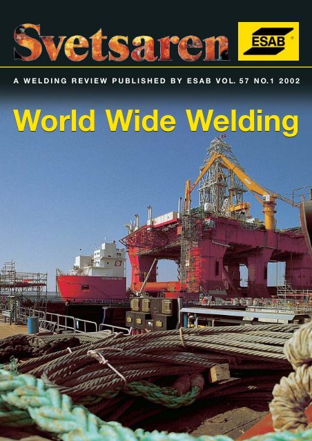
A WELDING REVIEW PUBLISHED BY ESAB VOL. 57 NO.1 2002<strong>World</strong> <strong>Wide</strong> <strong>Welding</strong>
A welding review published by ESAB AB, Sweden No. 1, 2002Articles in Svetsaren may be reproduced without permission but withan acknowledgement to ESAB.PublisherBertil PekkariEditorLennart LundbergEditorial committeeKlas Weman, Lars-Göran Eriksson, Johnny Sundin, Johan Elvander, Lars-Erik Stridh,Owe Mayer, Stan Ferree, Ben Altemühl, Manfred Funccius, Dave Meyer, Donna Terry.AddressESAB AB, Box 8004, SE-402 77 Göteborg, SwedenInternet addresshttp://www.esab.comE-mail: info@esab.sePrinted in Sweden by Geson Skandiatryckeriet, KungsbackaRepair & Maintenance.Contents Vol. 57 No. 1 20023Tank construction in Saudi ArabiaBuilding tank farms - the logistics of processchange, productivity, fabrication techniquesand distortion control as well as climateconditions are discussed in this article fromSaudi Arabia.22Modern cutting machines and techniques inthe shipbuilding industryIn addition to cutting, marking plays animportant role at shipyards. This paperdescribes different methods for marking as wellas processors for the surface cleaning of primedmaterial and new Windows-based controllers.10South Korea is today’s leading shipbuildingnationSouth Korea is in the top of the world’sshipbuilding league after a spectacular growthover the past 30 years.27<strong>Welding</strong> penstocks and coiled boxes for ahydropower plant using ESAB flux-coredwireAn aggressive environment with a hightemperature,high-humidity equatorial climatein the Amazon region in Brazil makes thechoice of welding process very important13<strong>Welding</strong> components for the petrochemicalindustry at Sirz Montaggi srlItalian company Sirz Montaggi srl isfabricating components for the petrochemicalindustry in different parts of the world31ESAB Automation North AmericaA new business unit within ESAB Canada willsell and service automation equipment andproducts throughout the USA, Mexico andCanada.16Stubends & SpatterShort news33ESAB in the automotive industryESAB developments within welding processes,consumables, power sources, automationequipment and robot interfaces pave the wayfor the automotive industry20ESAB/Capitol Steel case studyWith installation of new technology as a keypart of its philosophy the US Capitol Steelcompany cuts labour costs and stayscompetitive
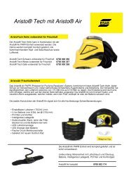
Tank construction in SaudiArabiaby Howard J. Hatt, Sen. M. Weld. IBuilding tank farms with automated welding processes iscertainly not new or innovative, but it was to the fabricatorinvolved in the contract discussed in this article. The logisticsof process change, productivity, fabrication techniques anddistortion control are discussed, as well as the infl uence of theextreme climatic conditions.Figure 1. A general view of the site during the early stagesof construction which adequately shows the size of the tanksand the number of welded joints involved.BackgroundThe contractor, Al-Khadari Heavy Industries (KHI),based in Dammam, is active in a variety of multi-milliondollaractivities which are fairly diverse and includehighway construction and street cleaning, as well as steelfabrication. The company is owned and managed by theAl Khadari brothers and was founded during the early1950s by their late father. It has grown progressivelyever since and entered the steel fabrication industry in1985 with the erection of the main fabrication complex,also in Dammam. This division is managed by Mr AliAl-Khadari, an energetic US-educated engineer, who isdedicated to improving the scope and technical abilityof the company. The company was recently audited byAramco (Arabian American Oil Co), which demandsvery high standards from its suppliers and their employees,but ultimate accreditation will provide access toa massive new market.Tank contractKHI has built small tanks on site previously, althoughnothing on the scale of the current contract, whichinvolves the construction of four tanks 90 metres indiameter and 20 metres in height. The contract wasawarded by the Royal Commission and this organisationis responsible for the provision and construction of allthe civil amenities within the eastern province of thekingdom. The steel construction projects are managedwithin the commission by the consultants Bechtel, whoalso act as the QA authority for the client at the site.The tanks are for the drinking water authority andare being built to expand the capacity of an existingfacility adjacent to the site, which is located in theindustrial city of Jubail. Desalinated water from theGulf is treated, stored and pumped by this facility tothe capital Riyadh, which has minimal natural waterresources.Western or S-E Asian contractors are no longerable to compete with local companies for this type ofwork, so, in this case, TTN of Japan supplied the designsand all the steelwork. The roof supports, floor platesand shell plates arrive virtually in kit form, havingbeen cut to size and, where appropriate, pre-rolledwith machined weld preparations, all to a high standardof accuracy.To date, KHI’s experience of tank building hasfocused on MMA stick electrodes, a process which isstill predominant in the Middle East. As with mostcontracts of this size, completion dates have to becomplied with and the imposition of penal clausesadds to the incentive. There is insufficient labour withthe required skills available locally, so personnel arerecruited from agencies, usually in India, Pakistan andthe Philippines. So the use of MMA on a contract ofthis kind would be extremely labour intensive with lowsvetsaren nr 1-2002 •3
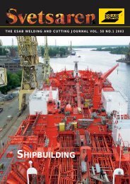
The Railtrac FW1000 machine is driven by the 40Vauxiliary power supply from a MIG power source andan electronic interface permits the remote controlof welding parameters. The equipment is capableof welding in the vertical, horizontal and overheadpositions and has a pre-programmable memory whichsimplifies on-site operation. It can also be used forcutting when fitted with a suitable burning torch. MMAwould still be extensively employed on joints unsuitedto automation and as a back-up where necessary tomaintain the production schedule.<strong>Welding</strong> consumablesThe consumables for all the welding processes wereselected from the ESAB range as follows:Figure 2. An A2 Circotech machine welding the horizontaljoint between the second and third courses.productivity and aggravated by a higher incidence ofdefects, especially in site conditions with welders ofvarying capability.In this situation, KHI had to review the options forthe introduction of higher productivity processes.ProcurementUltimately, it was decided that investment in fullyautomatic welding equipment to weld all the joints oneach tank was not justified, especially if the machineswere under- utilised after completionESAB was chosen as the manufacturer from whomto seek advice due to the vast product range andexperience available. The local ESAB agent Medcocarries large stocks of consumables and spare parts andhas knowledgeable aftersales personnel and serviceengineers. In addition, this is backed up by ESABMiddle East in Dubai. No other welding house in theregion could offer such comprehensive support.The submerged arc process was selected for allthe tank floors and circumferential joints on the shellsand this was provided by the ESAB A2 Minitrac deckwelders and the ESAB A2 Circotech single-sided girthwelders with ESAB LAF1000 DC power sources.The use of fully automatic MIG/MAG with gasshielded,flux-cored wire was the preferred option forthe vertical joints to be provided by the ESAB RailtracFWR1000 machine, together with the ESAB LAW400power sources and MEK4 wire feeders. This packagewas considered to be more cost effective than the moreproductive electrogas process, as the equipment ismore versatile and infinitely portable, allowing it to beadapted for a wide range of alternative applications.•4svetsaren nr 1-2002Process Consumable AWSMMA OK 46.00 E6013OK 48.00E7018FCAW OK Tubrod 15.14A E71T1SAW OK 12.32 / OK Flux 10.71 EH12KMMAThe use of an E7018 MMA electrode was specified forthe shell because basic low-hydrogen types produce highpurity weld metal with more dependable mechanicalproperties than rutile types. The only disadvantage is thehigher degree of welder skills required and the storageof these electrodes in site conditions is more critical. Inview of the latter and the high humidity, especially inJuly/August, all the OK 48.00 was supplied in Vacpacs.FCAWWhen high productivity is required for large volumes ofvertical-up welding, the most cost-effective consumableis the rutile E71T1 flux-cored wire. It will only operate inthe spray transfer mode, which ensures high depositionrates and produces a rapidly freezing slag to maintaingood control of the molten weld metal and produce aflat profile. OK Tubrod 15.14A has exceptional runningcharacteristics and produces minimal spatter with CO 2Figure 3. Vertically welded joint showing the fl at and smoothprofi le produced by the Railtrac machine and OK Tubrod15.14A. The minimal spatter also simplifi es preparation forpainting.
shielding gas, which is commercially beneficial, as Ar-richgases are very expensive in the region.SAWOK12.32 is a copper-coated solid wire which, when usedin combination with OK Flux 10.71, produces a nominalall-weld metal UTS of 550 N/mm 2 . The flux is a basicagglomerated slightly alloying silicon and manganesetype with a basicity index of 1.6, which is lower than thefully basic OK Flux 10.62, which has a basicity indexof 3.4. OK Flux 10.71 therefore allows for greaterflexibility with regard to the scope of applications andcombines excellent weldability, weld appearance andslag release.<strong>Welding</strong> proceduresAll the welding procedures had to be pre-qualified inaccordance with ASME IX and the tank design code,which was API 650. The butt joint procedures were allcarried out on 22 mm plate, which then qualified themfor use on the minimum thickness of 10.5 mm up tothe maximum of 32.5 mm. Other procedures involvedfillet and lap joints.Flexibility was required for the vertical joints, soprocedures were submitted using both MMA and fluxcoredwire. The root pass, however, was to be carriedout with MMA in all cases, due to the joints beingdesigned with open gaps to allow full penetration fromone side.None of the procedures required full mechanicaltesting. This was not considered necessary, as the tankswere to be built with ASTM A36 and ASTM A283 lowto medium tensile steels and were for the storage ofwater at relatively high ambient temperatures.Figure 4. Capping passes of horizontal joint welded by 2Circotech with OK 12.32 and OK Flux 10.71. The excellentweld appearance and blending of the three passes is readilyapparent.The acceptance criteria were therefore based on visualand radiographic examination, which also applied tothe welder qualification tests.ProductivityAll the shell plates are 14.5 metres long and 2.5 metreswide. With a tank circumference of 282 metres, 20 platesare required per course, which means that 50 metres ofvertical welding have to be completed on each. Thesejoints are subjected to the lowest productivity thewelding position, so a productivity comparison will bemade between MMA and FCAW on a 15 mm singleV joint.Productivity comparisonDeposition ratesMMA OK 48.00 2.5 mm@ 90 Amps = 0.8 kg/hrOK 48.00 3.0 mm@ 120 Amps = 1.3 kg/hrFCAW OK 15.14 A 1.2 mm@ 190 Amps = 2.8 kg/hrTheoretical joint volume @ 180 cm/3 = 1.41 kg/mWeight of root pass = 0.20 kg/mWeight of fi ll and cap = 1.21 kg/m(Note: Joint volume includes 3 mm reinforcement.)Arc times MMA FCAWRoot pass 15 min/m 15 min/m (mma)Fill and cap 56 min/m 26 min/mTotal arc time 71 min/m 41 min/mActual time@30% duty cycle 234 min/m@50% Duty Cycle 82 min/mor 3 hr 54 min or 1hr 22minsActual time per joint @ 2.5 m = 9 hr 45 min = 3 hr 24 minTotal saving by FCAW = 6 hr 20 min/per jointsvetsaren nr 1-2002 •5
Tank constructionFigure 5. A view of the annular plate segments on wich theshell is erected. The fully welded fl oor can also be seen, but isnot welded to the annular plate at this stage.Annular ringAs with many similar construction projects, the initialactivity involves putting in the concrete foundations.The depth is specified in API 650 and will depend onthe dimensions and weight of the tank when full andon the type of ground, i.e rock, clay, soil or, in thiscase, sand.Steelwork commences with the laying and weldingof the steel segments that form the annular plate whichruns around the outside circumference of the concretebase. It is on this plate that the tank shell is built, butit is not welded to it until the third course is erectedand the shell has been dimensionally checked for theaccuracy of the circumference. Should any distortionhave occurred during the welding of the first two courses,the shell is still floating or free to move. In this way, anycorrection is more easily accomplished.The annular plate is 14.2 mm thick and the sectioninside the shell ultimately becomes an integral part ofthe tank floor, which is only 9 mm.This ensures greaterstructural integrity where it is needed, as the bottomcourse of the shell is 32.5 mm thick. The tank floor itself,however, is only under a compressive load from thetank contents as well as the roof and its supports, hencethe reduced plate thickness.which are more than adequate for the service conditionsand require no expensive weld preparations. A methodof this kind also simplifies production enormously as itallows greater tolerances with regard to fit-up. In fact,as is the case with the majority of tank construction,great reliance is placed on “dogs & wedges” for thepositioning of plates, as they are inexpensive to produceand can be re-used.It is essential that welding of the tank floor iscompleted in a strict sequence from the middle outwardsand even then every third longitudinal seam is leftunwelded until completion of the others. This is to avoiddistortion, which can be exaggerated by the ambienttemperatures that can exceed 45°C in July and 50°Cin August. As an experiment, a check was made on thedegree of expansion by placing a chalk mark at thejunction of the annular plate and the tank floor, beforethe two had been welded. This was done at 1 pmwhen the ambient temperature was 45°C and the platetemperature was 80°C. At 6 pm, a second line was madeat the same junction when the ambient temperature hadgone down but only by 10°C. The result was a gap of 30mm between the two marks, making a total of 60 mm onthe diameter, so the effect of even greater temperaturegradients can be readily appreciated. It is for this reasonthat the welding of the annular ring to the floor is carriedout when the ambient temperature is at its highestand after the bottom shell plate has been welded tothe annular plate.Should a large repair or the replacement of acomplete floor plate be necessary for any reason, theresult would be catastrophic. The affected area woulddome up and recovery might involve the renewal ofthe entire floor.Shell fabricationThe tank wall sections are 2.5 m high, requiring eightcourses to complete the overall design height of 20 m.Internal pressure from the tank contents is progressivelyreduced upwards as is the weight of the shell. Thebottom course in this case is therefore thickest at 32.5Floor areaThis is where welding commences in large volumesand the tanks in question require a large quantity ofplates measuring 9 metres by 2.5 metres to completethe floor area. In all, the weld lengths run into hundredsof metres, which is why SAW was selected as the mostproductive and cost-effective alternative to MMA.As previously mentioned, the floor is only subjectedto compressive loads and so through- thickness buttjoints are not required. All the joints are of the lap type,•6svetsaren nr 1-2002Figure 6. A two-pass lap joint as applied to all fl oor joints andwelded with OK Autrod 12.32 and OK Flux 10.71.
mm and each successive course in made from thinnerplate because it carries less weight than the previousone until the top, which is only 10 mm.The control of distortion is also vital during shellfabrication. With this in mind, all the lower and thickerplate courses have a double”V” weld preparation,thereby reducing the amount of weld metal to fill thejoint and permitting a balanced welding techniqueto control the distortion. All the courses with 15 mmplate and below have single “V” preparations, as it isimpractical to use double “V”. In all cases, the includedpreparation angle is 45 degrees, serving to reduce weldmetal and the risk of distortion still further.Erection commences with the first two coursesbeing tacked in position on the circumference and thevertical seams were clamped with dogs and wedges soas not to disturb the open gap.All the root passes were welded using 2.5 mm OK48.00 and filling and capping were completed with either3.0 mm OK 48.00 or with the Railtrac FWR1000 andOK Tubrod 15.14A 1.2 mm. It would have been mostbeneficial to use automated FCAW on all the verticaljoints, but a plate shipment delay put the project behindschedule, necessitating the use of MMA in order torectify the situation. In all cases, however, FCAW wasused on the outside seams due to the vastly superiorweld appearance achievable with automatic oscillation.Initially, the capping passes were split weaved,because ASME rules dictate that maximum weavingshould be three times the diameter of the electrode.This had also resulted in complaints from the clientin respect to the valley between the capping passes orexcessive reinforcement, especially with regard to thesubsequent painting. These complaints were principallydirected at the MMA – since OK48.00 is an E7018 type,the welders had difficulty keeping the split beads flatdue to the restricted weave width.At this point, KHI did not have a welding engineerto assist them with the inevitable teething troublesassociated with such an abrupt change of weldingprocesses or to interpret the codes of welding practice.It was at this point that the author came into the pictureand the first change was to adopt full-width weaving ofthe caps, to the complete satisfaction of the client.So often an ESAB client has rejected a recommendationbecause of a particular rule, but in themajority of cases a clause will eventually appear to theeffect “unless agreed by the client”, which enables sucha change to be made.The use of MMA on the inside and FCAW onthe outside, however, was not without its problems,especially if a repair or two was required to the inside.The higher heat input from the MMA, plus any arc airgouging followed by more welding, could cause the jointto bow out, putting that section too far out of line withthe course above, and this did actually occur on oneoccasion. A problem of this kind contravenes the designcode dimensionally and causes considerable difficultyFigure 7. Guy ropes attached to the strong backs whichserve to reduce distortion, especially where MMA welding.welding the circumferential seam above it, so remedialaction was essential, but how? You learn somethingevery day and the experience of the KHI personnelsolved the problem by removing the outside weld andre-welding. The joint was pulled back into line and wasa classic case of distortion being used to advantagefor a change.The next stage was to weld all the vertical joints onthe second course, still employing MMA on the insideand FCAW on the outside, but additional precautionswere taken to avoid a repeat of the above problem. Byattaching hand-winched steel guy ropes to the strongbackswelded to the inside joints during the MMAwelding, excessive distortion was prevented. Defectswith the automated OK Tubrod 15.14 A were extremelyrare.<strong>Welding</strong> of the first circumferential joint with theESAB A2 Circotech machines could now proceed. Theoperators had received training in Dammam and thewelding procedures were pre-qualified; no problem.Experience has demonstrated that this, however, is rarelythe case, as welding in production brings difficulties thathave not been foreseen. Since the tanks are 282 m incircumference, it would take one machine eight hoursto complete one pass or four hours for two at averagewelding speed. Anything that could be done to reducethe number of passes would therefore be a bonus andmanagement pressed to achieve this.The outside preparation in the 32.5 mm plate wasestimated at five passes but was completed in four byusing the maximum amperage permitted by the PQR.Weld deposit dimensions were controlled by weldingspeed, welding head angle and to a lesser degree thevoltage, which was kept as low as practicable. Thisis especially important on the root pass to maximisepenetration into the 3 mm root face and reduce thedepth of back gouging on the inside. On subsequentfilling passes, voltage control is vital to maintain eachsvetsaren nr 1-2002 •7
pass in the desired position and prevent cold lappingand the attendant risk of fusion-related defects.The design code permits a maximum of 5 mmmisalignment in the straightness of the shell sides. Apoint is measured at one metre each side of the jointand a two-metre long straight edge placed between thetwo reference points. Any gap between the straight edgeand the shell at the weld junction must be less than 5mm. Following back gouging of the inside, more weldmetal would be required to fill that side with the riskof distortion. With this in mind, the last capping passwas omitted from the outside until after the inside wascompleted. This was a precaution worth taking, as thesmall amount of distortion that did occur was rectifiedby the last capping pass on the outside.The welding performance of a submerged aremachine will only be as good as the preparation that Figure 8. The roof support bases clearly showing the stainlessis presented to it. <strong>Welding</strong> the root pass on the outside rubbing plates. Corner fences will ultimately be welded to theproduced an excellent weld appearance and selfreleasingslag, but the converse applied on the inside,tank fl oor to restrict movement to within restricted limits.following back gouging and grinding, due to theirregularities produced. This is aggravated by the fact Realistically, only MMA and solid wire MIG/MAGthat welding is in the HV position with no assistance using dip transfer could be considered using the semivertical-downtechnique. Ultimately, MMA was chosenfrom gravity, so gouging must be kept to the minimumrequired and must be as uniform as possible.for portability and ease of use, especially as welding onThe incidence of defects with the SAW A2 Circotech the inside of the tank is in the overhead position. Themachine is also extremely rare and, when they do electrode selected was OK46.00 3.0 mm, which is anoccur, they are usually attributed to human error in the E6013 type and is capable of vertical-down and touchsetting of welding parameters or a malfunction. With welding, combined with easy arc striking.the judicial setting of all welding variables, including The bases of the tubular roof support columns arehead angles, a truly excellent surface appearance and of interest as they are also free to move to a certainflat profile can be achieved, regardless of the number of extent. A 316L stainless steel plate is welded to theoverlapping passes. This is especially true when such a bottom of each column and this rests on a slightlyversatile flux as OK Flux 10.71 is employed.larger rubbing plate, which is welded to the tank floor.Stainless steel angle fences are welded to the rubbingRoofplate to restrict movement to only that required toaccommodate roof expansion and contraction. TheseApart from the ancillary pipework and so on, the roofcomponents have to be made of stainless steel because,is the last major welded fabrication to be completed.if they were painted, the rubbing would remove theThis again involves the welding in situ of a considerablepaint and corrosion would set in.number of 4.5 mm thick plates, all with lap joints, butthese are welded on both sides. The roof slopes up tothe centre at an angle of 10 degrees and is supported Alternative equipment and processesby a systematic arrangement of RSJs, which are in turn ESAB can supply welding equipment and processes thatbolted to the tubular columns.are capable of higher productivity, assuming the quantityThe ambient temperature gradients on such a large of tanks to be built and the additional investment isarea and the degree of thermal expansion that can be justified.experienced dictate that the roof is not welded to theshell. An angle ring is welded to the outside edge of SAWthe roof and this fits over the tank shell like a lid on The ESAB A2 Circotech machine can be supplied as aa tin, but with sufficient space to permit maximum two-sided machine for single- or twin-wire operation,contraction.which allows the inside and outside circumferentialConsidering the thickness of the plates at only 4.5 seams to be welded simultaneously. The first weldingmm, a welding process which allows for rapid welding head precedes the other by about 50 mm, so that thespeed and a small weld cross-section is preferred. A second operator can judge the penetration producedseal against the weather and airborne sand is the main by the lead head by observing the heat spot, i.e. dullobjective, as opposed to maximum structural strength. red would be insufficient while yellow would probablyA small weld deposit produced at high speed would be enough. The preheating effect also aids penetrationalso serve to reduce distortion.from the trailing head.8 • svetsaren nr 1-2002
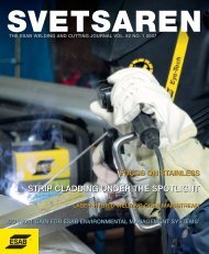
CO 2 or Arc 20% CO 2gas shieldCored wireelectrode<strong>Welding</strong>arcWire guide nozzleMolten weld poolMobile water-cooledcopper shoesment may therefore face long periods of inactivity,unless, like KHI, they are involved in other more generalfabrication activities. The initial investment strategyof maximising productivity for the smallest capitalexpenditure while maintaining flexibility for the futurewas certainly vindicated. It is only the A2 Circotecmachines that are restricted as far as alternativeapplications are concerned in comparison with the A2Minitrac, Railtrac and the LAW 520 W semi-automaticMIG/MAG machines, which are completely flexible. Inaddition, there is the dramatic increase in productivity,together with the minimal incidence of defects andsubsequent repairs. In combination with the reducedmanpower and individual skills required, this hasensured a full return on the investment within the lifeof the contract.Completed weldFigure 9. Schematic view of the electrogas process.The offset between the two heads also allows any gasproduced by the lead head from the welding process toescape easily. If the two heads were adjacent to eachother, the gas could be trapped between the two weldpools, resulting in surface or underbead porosity.The principal benefit, however, is in productivity,as labour-intensive and time-consuming back gougingis totally eliminated.AcknowledgementsThe author would like to thank the following people fortheir assistance in compiling this article, as well as MrAli Al-Khadari for giving his permission to publish it,Mr S. Rasool, Technical & Commercial Manager, MrC. Chamberlain, Construction Manager, and Mr C.V.Agilan, Construction Engineer.Electrogas weldingThe ESAB Vertotech electrogas welding machine permitsthe welding of all vertical joints in one pass up toa plate thickness of 35 mm. The process is similar tocontinuous casting as the weld is produced between twowater-cooled copper shoes, which progress up the jointwith the molten weld pool to hold it in place until it hassolidified. Oxidation of the weld pool is prevented by theArgon-rich or CO 2 shielding gas and the weld metal isprovided by specially developed flux-cored wires.When the plate thickness exceeds 20 mm, oscillationis required to ensure full side-wall fusion and themachine has a motorised slide for this purpose. Contolof weaving amplitude, speed and dwell times can all bepre-set before welding commences.Deposition rates exceeding 12 kg/hr are possible, sothat travel speeds can be measured in metres per hour.The 15 mm butt joint in the productivity example couldbe completed in 25 minutes, at only 450 amps.SummaryTank contracts of this size are not awarded frequently.Fabricating companies with the experience and equip-About the authorHoward J. Hatt, Senior M. Weld. I was in thewelding industry for 40 years, initially withMurex, then BOC and ultimately the <strong>Esab</strong> Groupin the UK.Since 1973 he held sales and technical managementpositions both in the UK and exportmarkets, but moved into marketing on joiningThe <strong>Esab</strong> Group in 1984. Until he took earlyretirement in 1999 Howard Hatt was involvedin market development for cored wires andtechnical support to the group companies.He now spends his free time gardening aswell as building and flying radiocontrolled scalemodel aircraft, although is still available to ESABwhen required.svetsaren nr 1-2002 •9
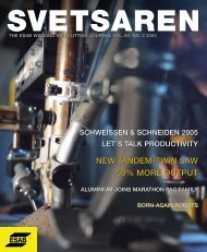
South Korea is today’s leadingshipbuilding nationThe rise of South Korea’s shipbuilding industry has been one ofthe most spectacular industrial phenomena of the past 30 yearsin global terms. This growth has taken South Korea to the topof the world’s shipbuilding league. Its shipbuilders currently have43% of new ship capacity on order.Korean shipyards have primarily focused on buildingbulk carriers, tankers and containerships, but they haverecently shown that they can also build complex vesselssuch as gas carriers, offshore rigs and FPSOs (FloatingProduction, Storage and Offloading).By concentrating on qualified technological knowhowand with their highly trained engineers, Koreanshipyards are today able to comply with and built toalmost any ship owner’s design requirements.DAEWOO shipyard with ESAB SeAHCorporationLocated in Okpo Bay on the island of Goje, off thesouth-eastern Korean peninsula, Daewoo Shipbuilding& Marine Engineering (DSME) had built 180 oiltankers by September 2001, including 70 VLCCs since1988, which corresponds to about 13% of the world’sVLCCs.Since the company was established in 1978, it hasdelivered more than 400 commercial vessels, covering awide variety of types and designs. Using state-ofñthe-artproduction facilities, DAEWOO is regarded as one ofthe most efficient and competitive producers of ultralarge vessels such as VLCCs, ULCCs and a numberof 320,000 dwt Very Large Ore Carriers (VLOC).DAEWOO also has the capability to construct hightechvessels such as LNG and LPG carriers, FPSOs anddeep-sea drilling rigs.DAEWOO operates the world’s largest dry dockmeasuring 530 x 131 x 14.5 m and equipped with a 900tlifting capacity gantry crane, which is registered in theGuinness Book of Records. This dock, together with asmaller 300,000 dwt dry dock measuring 350 x 81 x 14.5m and three floating docks, enables the yard to buildabout 40 vessels a year, plus 10 warships, submarinesand a number of onshore and offshore platforms andstructures.The current order book contains around 120 vessels,including 14 large LNG carriers. This will keep the yardfully occupied well into 2004.ESAB SeAH Corporation (ESC) was set up in 1985as a joint venture by The ESAB Group and SeAH Steel•10svetsaren nr 1-2002and it manufactures flux-cored wire, and stainless steelelectrodes, in Changwon, where it is very close to themajor shipbuilders such as DAEWOO, SAMSUNGand HYUNDAI.DAEWOO has developed an automatic weldingrobot, Danny, which is more compact and easy to manoeuvrethan conventional robots and provides greateraccuracy of operation. Since 1996, when DAEWOOinstalled the first welding robot, some 14 units havebeen installed on the large block assembly line. ESAB(ESC) supplies Core Weld Ultra 1.6mm for the Danny.This new welding robot for shipbuilding is a promisingsubstitute for workers who often have to endure harshand dangerous working conditions.Application information for Core Weld111RB & 111 UltraThanks to the higher productivity of cored wires infillet joint welding, the consumption of flux-cored wire(FCW) is much larger compared to other weldingconsumables. The following table shows one example atSAMSUNG S/Y where the percentage of FCW weldingis around 94%.Consumable Per cent (%)FCAW Welder 71.6mechanised 10.3robot 3.7GMAW 0.1SAW 11SMAW 1.2Gravity 1.8EGW 0.3Table 1. Record of welding consumables used at theSamsung Shipyard between July and September 2001.As can be seen in Table 2, fillet welds, mostly in Zincprimed plate, account for around 90% of welding inshipbuilding. The shipyard has devoted great attentionand effort towards mechanisation in order to save timeand to reduce the risk of inhaling the fumes generatedby welding over Zn primer-coated plate. Fig 1-3 show the
Ship grade Weld length – km (%)Fillet Butt TotalVLCC 588 (88) 81 (12) 669(single)PAX. BC (73K) 220 (90) 24 (10) 24497K 303 (88) 40 (12) 343COT64K 396 (91) 42 (9) 438CONT'Table 2. Weld length of fi llet and butt joints in shipbuilding.Figure 1. Mechanised system at shipyard (left: gantry type – single torch, right: TAMA type – twin tandem with 24 torches).most famous mechanised system for fillet welding andESAB (ESC) is supplying DAEWOO with CW111RBfor the 2Y steel grade and CW111 Ultra for the 3Ysteel gradeSupply is in 300 kg Marathon Pac bulk package, 1.4mm and 1.6 mm diameterFigure 2. Bead shape of C/W 111 Ultra.Figure 3. Micro andpenetration fi gure ofC/W 111Ultra.What’s next?The nation’s yards are now focusing increasingly oncomplex vessels such as gas carriers, offshore rigs andFPSOs. The first domestically-produced LNG carrierwas delivered in June 1994, while, more recently, anumber of passenger ferries have been launched, soship owners all over the world have come to regardKorea as being synonymous with high-quality ships atreasonable prices (see table 4).The growth potential of the Korean shipbuildingindustry is largely due to much-improved productivityand efficiency, driven by increasing labour costs inKorea and by the growing presence of China in theshipbuilding market.The work force currently has an average age of 39years, much younger than its Japanese counterpart.While Japan is experiencing difficulties in recruitingskilled staff to the shipyards, Korea does not currentlyhave these problems. Nevertheless, South Koreanshipyards are currently increasing their R&D efforts toimprove efficiency and productivity to avoid weakeningof their competitive strength in the future.svetsaren nr 1-2002 •11
Unique welding equipment1. <strong>Welding</strong> equipment: TAMA, company from Japan2. <strong>Welding</strong> process: TOP (twin tandem one pool) method3. Number of poles: Six poles (24 torches)4. <strong>Welding</strong> condition See below5. <strong>Welding</strong> materials FCW – Core Weld 111 UltraLeg Torch <strong>Welding</strong> condition Travel speed Stick-out Angle ( O ) Length between Anglelength (Cm/min) (mm) L & T (mm) adjustment(mm)A V5 ~ 6 L 430 36 *5 mm leg length: 130 25 50 25 Forwards &T 350 34 *6 mm leg length: 110–120 backwards: 7 O8 L 420 35 80T 340 347°50° 50° 50°50°1-2mm7°25mm1. Project name: SHELL BRUTUS TLP2. Applied welding consumable: D/S 81-K23. Wire consumption: 380 tonnes (Jan-Aug 2002)4. Requirements: CTOD (ASTM E1290): min 0.25 ab 0° (H.I=1.4kJ/cm)*TLP; Tension Leg Platform, *FPSO; Floating Production, Storage and Offloading, *CTOD; Crack Tip Opening DisplacementTable 3. <strong>Welding</strong> parametersWhat does the future hold?Since 1999, South Korea has held the top position inthe world’s shipbuilding league, ahead of Japan. Howlong will this situation continue? This will depend ona number of factors, such as the state of the worldeconomy, the strength of the Korean won and thetechnological development within related industries.However, on its current form, Korea will prove hardto beat!Korean shipbuilders are looking to transformquantitative growth into qualitative growth by focusingon securing a larger percentage of orders for highvalue-added ships, thereby acheiving higher profitmargins.Shipyards Project Amount ordered Amount left Amount dried Steel consumedVessel G/T Vessel G/T Vessel G/T MT/YHYUNDAI LPG 22 1.35M 113 8.47M 42 2.85M 1.05MRigLNG (Moss)DAEWOO VLCC 38 3.34M 91 7.75M 35 2.86M 0.70MF/C (big)LNG (membrane.)SAMSUNG FSO 25 2.19M 89 7.08M 30 1.70M 0.65MF/C (big)LNG (membrane.)HYUNDAI MIPO BULK 32 0.84M 68 1.72M 14 0.30M 0.12MF/CSAMHO BULK 16 0.95M 46 3.70M 22 1.07M 0.20MF/CLPGTOTAL 165 9.68M 494 31.27M 169 956MTable 4. Market analysis of shipbuilding (as of September 2001).•12svetsaren nr 1-2002
<strong>Welding</strong> components for thepetrochemical industry at SirzMontaggi srlby Bo Magnusson, ESAB AB, SwedenThe increasing use of products derived from the hydrocarbonsreferred to as oil and gas means that the industry working withthese products is experiencing steady growth. Before fi nal use asa consumer product, the raw materials are treated in a number ofphysical and chemical processes.Firstly, the raw material is cleaned, which involvestreatment to separate it from unwanted componentssuch as sand, water, carbon dioxide and hydrosulphide.During this first step, the acidic sulphide environmentalready imposes heavy demands on the componentsthat will come in contact with the raw material and thishas led to the use of highly corrosion-resistant materialssuch as stainless steel of different grades, higher Nicontainingalloys and titanium. The next treatment caninvolve the fractionating of naphtha into groups ofhydrocarbons of different chain lengths, which are moreviable on the market. If the composition of the naphthais dominated by the heavier hydrocarbons, it is possibleto split the hydrocarbons into shorter chains. This isdone in hydrocarbon crackers at high temperatureand pressure.For temperatures below 250°C, carbon steels arefrequently used. For higher temperatures, chromium andmolybdenum are added to improve creep and corrosionresistance. The pipe steel grades used for petrochemicalcomponents are normally those described in the ASTMmaterial specifications for refinery service.GradeP1P11P22P5P9P91Alloy typeC–0.5 Mo1.25Cr–0.5 Mo2.25Cr–1Mo5Cr–0.5Mo9Cr–1Mo9Cr–1MoNbNiVIf H 2 S is present, it is necessary to use stainless steelgrades 321 (18Cr8NiTi) or 347 (18Cr8NiNb) for claddingreactors or for piping in high-temperature service.Since piping is a frequent structure in these constructions,the welding of pipes is an important activity.As mentioned earlier, the quality requirements are veryFigure 1. TIG welding of Inconel pipes.high and the normal welding processes are TIG forwelding the root and SMAW for filling layers.These are only some examples of components thatare welded, where the requirements that are imposedon the consumables are very high. Some interestingcomponents will now be examined in greater detailin terms of consumable selection and use. Thesecomponents have been constructed at Sirz Montaggiosvetsaren nr 1-2002 •13
Figure 2. Mounting of the start-up heater.srl in Porto Marghera outside Venice, Italy. Mr GianniPistore, the welding engineer at Sirz, was kind enoughto show the components under construction. Thiscompany’s production includes components for amethanol plant in Central Africa, an ammonia/ureaplant in Egypt, petrochemical heaters for Pakistan anda fertiliser complex in Venezuela.For the methanol plant, Sirz has built 40 moduleheaters for ethylene. Each heater has 21 catalyst pipes inInconel 600. The pipes are produced by centrifugationand are welded to an Inconel 800HT manifold at oneend and a P11 manifold at the other end. The Inconelpipes were welded with OK Tigrod 19.85 and the P11pipes with OK Tigrod 13.12.Bi-productsaltorWaste gasrecoveryRecycleREACTORRemoval ofcarbamateNH3CO2H2OUrearecoveryUREAUFigure 3. Simplifi ed fl ow chart of the production of urea.•14svetsaren nr 1-2002Figure 4. Mounting of waste train water heater.
<strong>Welding</strong> the manifoldsAnother important product is urea, which is a nitrogencontainingfertiliser, that can be synthesised fromammonia. As mentioned above, temperature is importantand once again one step in the process is to heat thereactants and Sirz has built a ”start-up heater” for aNH 3 /urea plant. This is constructed from four pipes,each 200 m long, formed to produce a helicoil. The pipeshave the following composition, ASTM TP 347H, andwere welded with Siderofil TIG 347 in the root andSMAW Filarc BS 347 for the filling.Another component for this plant is seven coilbanks for waste heat trains. They are constructed froma number of different grades of heat-resistant materials,ranging from carbon steel to T1, T22 and T91.The carbon steel was welded with Filarc 35S withSiderfil Argon in the root, T1 with Filarc KV2 and OKTigrod 13.09 for the root, T22 with Filarc KV3L andOK Tigrod 13.22, T91 with OK 76.98 and OK Tigrod13.38 in the root.For another fertiliser project, twelve heatersweighing up to 260 tonnes were assembled by weldinga large number of pipes of different qualities in bogovens. The materials were of the types A106, P11, P22,304H and 321H.The amount of welding is measured by the lengthof the welds and, in the case of the pipes, 26,000 inchesof welding were performed. Many of the welds wereperformed in difficult positions, which explains why therequirements imposed on the welding properties for theSMAW consumables are very high. The pictures showthe welders in action.The demand from a company like Sirz Montaggisrl on a wide range of consumables emphasises theneed to have a complete supplier like ESAB. The fullassortment and good deivery are important factors forSirz Montaggi srl when a supplier is chosen and ESABcan fulfil those requirements.Figure 6. Pipe welding in diffi cult positions.About the authorBo Magnusson is the Group Product Manager formild steel and low-alloyed electrodes at ESABEurope headquarters in Gothenburg.He has studied at the Chalmers TechnicalUniversity in Gothenburg and after a degree inInorganic Chemistry he started in the developmentdepartment at ESAB and has for the lastten years worked with product marketing.Figure 5. Some of the welders in action.svetsaren nr 1-2002 •15
From the demo of mechanisedwelding of an SMO pipe.Surfacing crossings on Nordic <strong>Welding</strong> DaysEast-Siberian Railway Last year, on 6 and 7 November, theNordic <strong>Welding</strong> Days were organisedby the ESAB Segment SupportDepartment. The seminars were heldin Gothenburg at the Quality Hotel11 and the ESAB Process Centre.Despite the fact that it took placeshortly after the Schweissen &Schneiden Fair in Essen, Germany,ESAB, a newly appointedthis event attracted some 75 people.The seminars were full of interestinglectures with different applica-IPLOCA memberOn 13 June 2001, ESAB was grantedtions. A new feature this year wasmembership of IPLOCA (InternationalIn the summer of 2000, at a new shop the inclusion of practical weldingfor a rail -welding train (RWT-32) demonstrations as well.Pipe Line & Offshore ContractorsAssociation), the service andat the Misovay Station, under the The lectures were as follows:guidance of RPF “Plazmoprotek”, Norms and standards, A modern pipecommunications network for pipelineand offshore construction whichwork began on the automatic surfacingof worn crossings. The surfacing cated welding repairs at a nuclearmill and welding methods, Compli-is operational in 125 countries.is done using equipment and materialsfrom ESAB. The universal LUA stainless steels, New steel types inpower plant, Synergic cold wire inESAB’s application was approvedby IPLOCA for its extensive400 inverter power source, the MED the offshore industry, Robot stationsexperience and reliability in the304 wire feeder, the PSF 400 weldingtorch and the mechanism for lopment at the Volvo Aero Corp andnow and in the future, <strong>Welding</strong> deve-supply of welding equipment, consumablesand technology to pipelineautomatically moving the torch – Wind tower production – simulationengineering and construction. LettersRAILTRAC BV – are all applied. and control of welding processes.of reference from ESAB’s pipelineThe surfacing tip and rail wings of The practical demos at the processcentre were: Robot weldingcustomers also contributed positivelyworn crossings made of manganeseto the decision.steel are repaired using OK Tubrodur with MCW in thin plate, mechanisedAll ESAB units will be included15.65 self-cored wire. The surfacing FCW welding overhead, mechanisedwelding in an SMO pipe, Syner-in the official IPLOCA directoryof these crossings takes place on aand ESAB consumables will displayspecial milling machine and they are gic cold wire welding and multielectrodeSAW welding.the IPLOCA symbol, which is wellthen stowed on reception-despatchknown world wide.railway sidings. In 2000, the repair The participants were very interestedand many questions wereFor further information, pleaseof about 100 crossings by surfacingcontact:and other forms of build-up was asked after each lecture. We hopeESABscheduled on the East–Siberian that we will see the same and perhapsMarketing Manager PipelinesRailway.even more interest next year.Mr. V. CarucciPhone: +39 02 97968295Fax: +39 02 97289300E-mail:vittorio.carucci@esab.se16 • svetsaren nr 1-2002
Friction Stir <strong>Welding</strong> inDenmarkDanish Stir <strong>Welding</strong> Technology,DanStir ApS, a company dedicatedto offering services to industry inthe field of R&D and the productiondevelopment of FSW technology,was established in the summer of2001.During the autumn of 2001, anESAB SuperStir welding installationfrom ESAB AB, <strong>Welding</strong> Automationin Laxå, Sweden, was commissionedat DanStir’s buildingcomplex in Brøndby near Copenhagen.The ESAB SuperStir machinewill be used for R&D on tool andprocess technology, as well as forproduction trials and production forcustomers.With a welding envelope of 3.5(W) x 15 (L) x 1.5 (H) metres anda down-force capacity of more than100 kN, it is able to weld large-scalecomponents in a variety of aluminiumalloys with a thickness of upto 25 mm.DanStir ApS and ESAB AB,<strong>Welding</strong> Automation, are collaboratorsin the EUREKA EuroStir ®project and are co-sponsors of GroupSponsored Projects on Friction Stir<strong>Welding</strong> at TWI in Cambridge, UK.For more information,please contactSylve Antonsson,e-mail: sylve.antonsson@esab.seFax: +46 584 411721.For more information on DanStir,please see: www.danstir.comInstalling a cross on a catholic cathedralOn Easter Day, 23 April 2000, a crosswas installed on the Cathedral of theImmaculate Heart God’s Motherin Irkutsk. The cathedral had beenbuilt as part of a project led by Polisharchitects and entitled “Irkutskindustry building”. However, theproduction of the cross and its installationat a height of 27 metres hadbeen entrusted to PRF “Plazmoprotek”.The cross was connected so thePRF “Plazmoprotek” welders hadhad to weld tubes with a diameterof 63 mm and a wall thickness of 0.6mm made from polished Chinesestainless steel to make the cross.The actual cross had a height of 6metres and a width of 3.5 metres.The horizontal and vertical crossbarsof the cross consisted of six tubeswelded together to form an exacthexagon.The cross was welded togetherby PRF “Plazmoprotek” using MIG(metal-arc argon-gas) welding equipmentfrom ESAB – the Caddy 200Professional and the LHN 200 withthe Heliarc HW 24 torch. The fillerwas 18-8 wire and the welding includedbutt, fillet and overlap joints.Almost all of the more than 100welds in the construction of the crosswere annular.After assembly and welding, the100-kg cross was transported on atruck to the cathedral and lifted bycrane to a height of 27 metres. Thewelders now had to fix it in placeand weld it to two towers, betweenwhich it was going to be stand, in theshortest possible time. The weldersfrom PRF “Plazmoprotek” managedto do the work in the allocated periodand they did it using the CaddyProfessional LHN 140 and OK 61.30welding electrodes from ESAB. Thereinforcement of the cross on thetowers took the form of six beamsmade of stainless material. As aresult, it looks as though the crosssoars above a temple. Father Peterwas delighted with the quality ofthe project and the time it tookto complete. On 8 September 82000, the solemn consecration ofthe new Catholic Cathedral of theImmaculate Heart God’s Mother inIrkutsk took place.svetsaren •17svetsaren nr 1-2002 nr 1-2002 •17
The ESAB Knowledge Centre on InternetWith the launch of the new ESABEurope internet site (http://www.esab.net/) during Schweissen& Schneiden 2001, ESAB publisheda completely new technical sectionfor students, welders and weldingengineers, The ESAB KnowledgeCentre.Here you will find a wealth ofdetailed information on welding &cutting processes and case studiesof industrial applications from practicallyany industrial branch. Alsowe included all recent issues of ourtechnical magazine Svetsaren-TheESAB welding & cutting journal,and new issues will be published onthe internet even before the papercopy is being distributed, so thatyou will have access to the latesttechnical information in the earliestpossible stage.In addition, you’ll find an overviewof the guiding software and salesliterature available from ESAB, tobe ordered or freely downloadable.Dedicate some time to browsethrough this very interesting partof the ESAB site, and maybe youcome across exactly that piece ofinformation you were looking for.For information on the ESAB knowledgecentre contact:ben. altemuhl@esab.nlSimple mechanisation with new process packageother using a CAN bus communicationsystem.ESAB After Sales, Equipment Operations,in Laxå, Sweden, has produceda range of particularly successfulrobot welding packages based on theAristo 450 power source. They havenow been supplemented with a MIGprocess package of universal type,suitable for use with robots andmechanisation processes of all kinds.More than twenty of these packages18• svetsaren nr 1-2002have already been sold.The MIG process package isbased entirely on standard components:the Aristo 450 power source(ESAB’s most advanced inverterpower source), together with thePUA1 control unit, an interface unitfor connecting external equipment,and the Mech/MEK wire feed unit.These components are linked to eachReliable communicationAll communication with externalunits, such as the robot or mechanisationequipment, is channelledthrough the interface unit. Thisensures that installation is fast andstraightforward.The PUA1 control unit can store96 sets of welding data; 186 synergiclines are already preloaded and theuser can create additional customlines if required.Danish interestESAB Denmark has installed thefirst MIG process packet at HadiInternational, a company whichmanufactures agricultural machinery.The prospects are excellent and asecond delivery from ESAB Laxå isdue within the next two weeks. Afurther eight sets are due for deliveryover the next two months.
Alstom increases production using ESAB’s welding equipmentESAB has received an order forfully automatic narrow gap weldingequipment from ALSTOM PowerAG Switzerland.The order is divided into twoparts; the first order involves a fullyautomatic narrow gap laboratorymachine and the second comprisesthe replacement of the welding systemson ALSTOM’s two existingwelding gantries.ALSTOM is involved in the productionof generator and turbineaxles. The equipment for weldingconsists of a TIG narrow gap weldingstation where the root passes arewelded. At this welding station, theaxle sections are welded in a verticalposition on a turntable.The narrow gap welds are performedby two welding gantries withroller beds and head and tail stocks.The primary objective of the newpurchase of welding equipment isto increase the level of productionand automation. The main featuresthat attracted attention to ESAB’snarrow gap equipment were the:• Pivoting torch, optimising the positioningof the wire when weldingdeep down in narrow gap joints• Automated joint tracking and positioningof the wire• Data recording of the competewelding procedureUntil now, the welding stationhas comprised old Hulftegger weldingequipment with a local Swissmanufacturedgantry, roller beds,head & tail stock.As the replacement time for thewelding equipment had to be minimisedand the reorganisation ofALSTOM’s workshop was to bekept to a minimum, it was decidedthat only the welding equipmentwould be replaced.Also included in the scope ofsupply is the equipment for positioningthe welding system over theworkpiece, including a 2.5 m longvertical boom that holds the wireand flux equipment. As ALSTOMuses two 300-kg wire drums and an80-litre flux tank, the vertical boomfor the welding equipment wouldhave to be of the heavy-duty type.The positioning of the weldingequipment comprises the following:• Carriage with linear slide supportand rack & pinion drive• Vertical boom with motor andscrew gear• S4/S5 slide crossDuring the technical negotiations,it was found that the simplestway of changing the welding systemwould be to replace the whole upperpart of the existing welding gantries.The reason for this was that extensivemachining and fitting of an attachmentplate to hold the welding equipmentwould be needed in order to fitthe equipment on the upper part ofthe existing gantry.The laboratory unit will be deliveredduring the autumn of 2001 andthe second part of the order will takeplace during the second quarter of2002.AlcoTec Wire Corporation Receive ISO 9000 RegistrationAfter many years of producing premiumquality aluminum welding wirein accordance with a quality systemmodeled on ISO 9000, AlcoTec WireCorporation was recently awardedregistration by QUASAR, the qualitysystem registration division of theCanadian <strong>Welding</strong> Bureau. This ISO9000 quality system registrationwill complement AlcoTec’s otherinternational certifications includingThe American Bureau of Shipping,Canadian <strong>Welding</strong> Bureau, KoreanRegister of Shipping, Lloyd’s Registerof Shipping and Det Norske Veritas.AlcoTec Wire Corporation is locatedin Traverse City, Michigan USA.svetsaren •19svetsaren nr 1-2002 nr 1-2002 •19
ESAB/Capitol Steel CaseStudyCapitol Steel fi nds mobile welding machine propels production– cuts labour costs by 25%.Figure 1. Capitol Steel uses the A6 Tandem Mastertracto make horizontal fi llet welds up to 7/16” (11 mm).Figure 2. A fi nished beam leaves Capitol Steel’s shop.Throughout its long history, Capitol Steel & IronCompany of Oklahoma City has relied on strategicmoves – on and off the shop floor – to reach new marketsand prosper. A key part of Capitol’s philosophy hasbeen the installation of new technology that increasesproduction rates and helps to keep the companycompetitive through changing times.•20svetsaren nr 1-2002Established in 1910, Capitol began as a fabricator ofconstruction rebar and eventually evolved into a globalfabricator of steel beams used in erecting cotton gins andmilitary hangars. During the middle of the last century,the company found success working on structural steelbuildings, with a concentration on fossil fuel powerplants. It was during the last decade that the companyfocused on welding flange webs on plate girders forhighway and railroad construction, which it performs inits 300,000 square foot facility.Capitol Steel was purchased in 2000 by the IowabasedRasmussen Group, a prominent bridge constructionfirm. To supply the needs of this partner companyand other prime contractors, Mark McCarty, operationsmanager at Capitol, is constantly looking for a means tospeed his pre-fabrication process, meet tight constructionschedules and provide consistent quality weldments.Capitol now employs 120 workers who do all thepre-fabrication work in house, building plate girders thatrange in weight from 15,000 pounds up to 100 tonnesand extend from 50 to 130 feet in length.Like all shop managers in his position, MarkMcCarty is concerned with cutting labour time andcosts. He decided to investigate the potential offered byan improved tractor-mounted submerged arc weldingmachine. “We were looking to replace some old equipmentand do some upgrades in the shop,” says McCarty.“We checked around with industry leaders and foundthat a mobile system was a reliable, fast technology.”To replace his outdated tandem sub-arc tractor,the unit he chose was a four-wheel drive A6 TandemMastertrac from ESAB. The power supplies selectedto complete the system were an LAF 1250 DC anda TAF 1000 AC. The OPC flux recovery system wasalso added.To permit horizontal fillet welding with two wires,the A6 Tandem Mastertrac was modified slightly. Thestandard A6 contact jaw assemblies were replaced withbent A2 contact tubes (part number 413511001) andthe A6 guide bars were extended by bolting two guidebars together.Capitol Steel uses this system to make 7/16”horizontal fillet welds. To make a fillet weld of thissize with its previous system, the company had toposition the beam to allow the weld to be made in theflat position.
Figure 3. Labor savings of 25% have been realized by theintroduction of the A6 Tandem Mastertac.“I was not familiar with this type of mobile systembefore,” says McCarty. “What drew me to this technologywas its capability to weld in a flat position with noturning. That saves considerably on material handling.We are now able to move the machine to the work andcut labour time.”“With this new tractor, we can do more welding andless re-positioning,” says McCarty.“I can set the beam down flat and that way I canweld down one side, turn around and weld down theother side without having to move the girder.”With his previous system, for each fillet weld thegirder had to be rolled into position – for a total of fourre-positions per girder. The new tractor enables weldingof the entire girder with only one re-position, therebyeliminating three of the moves.“This tractor welds flanges vertically and the web ishorizontal, so both flanges are in an identical position,”says McCarty. “Our old units ran in a trough position sothat the corner where the two flanges met was locateddown at the very bottom. Each time you wanted to weld,you had to position the connection into that 45-degreeposition. This new system offers greater manoeuvrabilitywith far less work.” This is of particular benefit to acompany such as Capitol Steel that works with suchmassive plate girders.Another benefit of welding the girders in thehorizontal position is that less tacking is required. “Itsaves on tacking the plates together, too,” says McCarty.“I don’t have to do as much of that. In the past, it took anentire shift or shift and a half to weld a girder together.Now I can complete two girders a day.”The company began to use the ESAB tractor whenthe Rasmussen Group assumed ownership over a yearago. Capitol purchased two of the units – one each inMay and August of 2000. Since then, McCarty says hisoperation has realised savings of approximately 25%in labour costs.Along with flexibility, the tractor offers PEH processorcontrol for automated, high deposition rate welding.“This eliminates human error,” says McCarty. Thetractor can store ten presettable welding parametersand offers capacity for heavy production welding usingup to 1/4 in. (6 mm) wire with 1,500 amps DC and/orAC power source.According to McCarty, the implementation ofmobile welding technology involves a learning curve onthe part of his operators. However, this is compensatedfor reasonably quickly in terms of controlled, consistentquality welds and higher production. Reaction tothe new system among his floor operators has beenpositive.Capitol Steel and Iron processed approximately4,000 tonnes of fabricating steel last year and alreadyhas close to 7,000 tonnes on the books for 2001. Priorto 2000, the company had fabricated a total of 5,000tonnes in the previous four years combined. McCartyattributes this dramatic growth to a new managementteam and their willingness to explore new avenuesof efficiency.As he says, “Labour saving is the key to helping usget jobs and stay competitive.”A6 MastertracThe A6 Mastertrac is a strongly-dimensioned selfpropelled,4-wheel drive, automatic welding machine.The advancded electronic control equipmentprovides high precision and the digital displayenables all the welding parameters to be presetaccurately – either beforehand or during welding.The A6 Mastertrac is easly to use and can besupplied for submerged arc welding( SAW) in single,twin or tandem version. It is also available for gasmetal arc welding (GMAW).Single Single Twin TandemSAW GMAW SAWMax load at 100% 1500 600 1500 2x1500duty cycly, AmpWire diameter, mm 3.0-6.0 1.0-3.2 2x2.0-3.0 2x3.0-6.0Wire feed, m/min 0.2-4.0 0.2-16.6 0.2-4.0 0.2-4.0Travel speed m/min 0.1-2.0 0.1-2.0 0.1-2.0 0.1-2.0Weight, kg 110 100 110 158svetsaren nr 1-2002 •21
Modern cutting machines andtechniques in the shipbuildingindustryby Klaus Decker, Managing Director, ESAB CUTTING SYSTEMS GmbH, GermanyCutting machines should provide constant cut quality,giving the user the confi dence to enable secondaryprocesses to be started without correction processessuch as the grinding of dross and so on.Figure 1. Water injection cuttingThe cut parts should also be within the geometricaltolerances, together with the correct cut surface andcut angle. Breakdowns on cutting machines should berepaired quickly so that production losses are kept to aminimum. To realise these goals, you not only requirea high-quality machine, CNC control also plays a veryimportant role. To obtain constant cut quality, thecutting parameters must be set with very high accuracy;every parameter must quite simply be programmable.To minimise breakdowns, the controller must have itsown checking system, which will report messages to theoperator or to the work preparation department. Forfast checking, the service department must have remoteaccess to examine the controller and check cuttingprograms and follow up cutting sequences.1. IntroductionThis paper focuses on the cutting machines that aremainly designed for the shipbuilding industry. It will•22svetsaren nr 1-2002describe different methods for marking, as well asprocesses for the surface cleaning of primed material.New CNC Windows-based controllers are described;they do more than simply guide the machine. Thesenew controllers are able to control the entirecutting process, automatically setting the correct parameters.Furthermore, via computer links and Internetconnectivity, the CNC and the machine can bechecked from the cutting machine supplier’s servicecentre.2. Cutting machine configurationsModern cutting machines are typically equipped withone or two plasma bevel heads, which enable thecustomer to perform straight cuts or bevel cuts. At someyards, the bevel head is also used to compensate thenormal bevel created from the actual plasma process.The torches are equipped with anti-collision devices,which protect them from crashes.
Figure 2. Powder markingFigure 3. Arc markingUsers often express a wish to have a higher markingline speed, as marking, from an immediate technologicalviewpoint, is regarded as a process secondary tocutting.While this is understandable, it can be disputed.When examining the comprehensive production layout,it could be argued that marking operations shouldbe improved in terms of readability, logistics andproduction directions, in order to speed up operationsin the following stages of production. Obviously, whatwe have is a case for development both quantitativelyand qualitatively and thereby good reasons for lookingat the systems available and new opportunities.A system of long standing is powder marking,using a special powder through an oxy-fuel burner.Depending on the circumstances, it permits line speedsof up to 20 m/min.Its drawback is that the powder is hygroscopic andthat the system is demanding in terms of maintenanceand upkeep. In spite of good upkeep, the line thicknesstends to vary unintentionallyOne recent development is the so-called plasmamarking, referred to as Arc Marker.This system produces what could be described asan etched line, but, as different to powder marking, itbreaks the paint coating and penetrates slightly into theplate surface, a feature which is not always regardedas desirable. For both systems, it is characteristic that inprinciple they produce only lines and only in one linethickness. Other types of marking, such as systems whichalso create an opportunity for production directions byusing different line characteristics or by marking withletters and signs, for logistical purposes, for example,were not available before the introduction of ink-jetmarking.Ink-jet marking permits marking speeds of up to20 m/min, for both line drawing and lettering. Thereadability is very good and the potential ink-jet markingcan add to an IPS (Integrated Planning System) in termsof improving logistics and the on-site availability ofproduction directions is obviously a major step forward.The improved cutting installation provides immediateoperational advantages, as well as major benefits in theproduction stages following cutting.Figure 4. Ink-jet markingThese machines are operated all over the world forsteel production at the yards. Oxy–fuel cutting can alsobe used, but mainly for weld edge preparation, thickerplates and strip cutting.In addition to cutting, marking plays an importantrole at shipyards. For many cutting installations, it is afact that the hours used for marking operations equalthe hours used for cutting.3. Surface cleaningTo cut welded plates (16–20 m) for further productionof exact measurement, there are panel line machineswhich have a span of up to 25 m. These machines are notonly used for cutting the edges for weld preparation.They also have to mark the positions at which thestiffeners should be placed.For shipbuilders, the manufacture of vessels fromshop primed material is a must. However, other steelfabricators also have to face certain production problemsfrom today’s protective paint systems. In particular,these problems are associated with the use of zinc-basedpaints and the like and the difficulties associated withsvetsaren nr 1-2002 •23
Marking Arc- Ink Jet Surface Cleaning Fine-beamMarker line line or letter Grinding shot blastingSpeed mm/min 20 20 20 15 10 4 6Residue % n.a. n.a. 8 5 2 15 40Table 1: Test results for variousmachining processes involvingmarking and surface cleaning.subsequent welding. If the paint is not removed, the Zncontent will result in a reduction in the welding speedand, in some cases, it will produce unwanted porosity,necessitating a repair routine. In other cases, it canresult in fillet welds with excessive throat sizes (or leglengths), which results in costly consequences in theform of unwanted and unpredictable deformations andinaccuracies at subsequent erection stages.There are various schools and viewpoints when itcomes to the solutions to these problems. One way hasbeen to integrate shot-blasting equipment in the cuttinginstallation and thereby obtain more or less clean metalsurfaces, where webs and stiffeners are to be weldedat a later stage.Figure 5. Grinding device for surface cleaning.Figure 6. Grinding device installation on panel machine for a shipyard in France.24 • svetsaren nr 1-2002
Vision NT include a familiar Windows graphical userinterface, network and Internet connectivity, kerfon-thefly with kerf override, programmable cuttingparameters, user-definable macro keys and enhancedshape library features.Figure 7. Windows-based CNC controller.Using fine-beam shot blasting, it has been shown thata target for surface cleanliness of 15% (i.e. max. 15%foreign particles, such as paint inclusions) can beobtained with a feed speed limited to 4 m/min (Table1).In the general production layouts of today, thisis a low moving speed and it does not fit in well withthe marking speeds. This is important as it is commonpractice to run the surface cleaning operation in parallelwith the marking operation and there is thereforean obvious need to match the processing speeds ofthe two.Table 1 shows the figures that can be obtained withtoday’s most advanced equipment for marking andsurface cleaning and it will be noted that very highproductivity, compared with previous techniques, isnow possible when operating at marking and surfacecleaning speeds of up to 20 m/min.The latest development in this field has been theintroduction of special grinding tools integrated in acutting installation (Fig. 5).The grinding tool permits a dramatic speed improvementand the surface cleanliness is also muchimproved (Fig. 6)4. New controller generation for cuttingmachinesThe Windows NT-based cutting machine controller isthe only “Open CNC” available in the cutting machinemarket. This powerful control features a Pentium-basedPS running Windows NT work station.This means that nesting programs, post processors,productivity, production scheduling or remote monitoringsoftware can be run straight on the control.Windows NT provides a stable, open architectureoperating system that the customer can use to run anyWindows or DOS programs. Some key figures of the5. Kerf on the flyTraditionally, there have been two ways to calculatethe kerf offset for a programmed path. Controls usingpre-kerf take a long time to calculate the running pathbefore executing the program. Controls using kerf onthe fly calculate the running path during run time, butrequire faster, more expensive processors.The Vision CNC calculates the entire kerf offsetpath, depending on modern microprocessor technology,before running a part, but enables the operator to adjustthe offset during program execution. This means thatthe operator can adjust the kerf offset after cutting thefirst part of a nest in order to continue cutting withoutrestarting the entire nest. The operator can scale thekerf offset between 50 and 150 per cent of the originalvalue. This results in easier operation, less wasted timeand material and more accurate parts.6. Programmable cutting parametersProgrammable cutting parameters allow process timesand parameters, along with feed rate and kerf values, tobe recorded in a file that can be recalled later. A cuttingparameter file can be created for each type of materiala customer cuts, so that the repetitive, critical task ofadjusting timers and parameters can be automated.The operator can manually select a parameter file orthe files can be called from within a part program,thus automatically setting the same values every time.The operator can also correct these files himself andcan store them.The newly developed “Adaptive Process Control”provides a higher level of process automation and qualityimprovement. All the necessary process parameters canbe programmed and are repeated during the cuttingprocess with a very high level of accuracy.• Cutting Speed • Arc Voltage• Kerf Offset • Initial Height• Pierce Time • Gas Flow• Preheat Time • Master up TimeThe machines must also be equipped with controlfunctions such as proportional solenoid valves, pressuresensors, flow controls, speed measurements and so on.7. Operator calling systemCutting machines with the latest open CNC controllerscan be run without or with very limited personnel.Connected telephone links to the controller permitstatus reports for the machine or the cutting process tobe sent to the user of the machine. The transmission takesplace using pre-selectable and prioritised telephonenumbers.svetsaren nr 1-2002 •25
Figure 8. SPD fi lesA number of machines can be supervised by oneoperator without any problem.8. Internet connectivityThis feature enables the operation of the entire machine(even over long distances) to be directly monitored fromthe cutting machine supplier’s service centre.Application• direct access to the machine from the service centre• in case of problems, the software department can traceall the functions of the specific machine on line• scope function can be transferred to the service centre(drive problems)• software updates can be directly installed from theservice centre• all machine parameters can be checked via specificsoftware• cutting programs can be downloaded from the cuttingmachine and checked at the factory• there is also the chance to correct NC programs andsend them backIn particular, intermittent errors, which occur atonly one time of the day or week, can be detectedwith Internet connectivity. The service centre canwrite (store) all the activities of the selected machine,including push-button pressing, cutting program, drivesystem operation and so on. If an error occurs, theservice department can check all the functions thatwere executed at that particular time to diagnose thecause of the error.plasma consumables. The cutting torches are fed withthe right parameters to guarantee the best, repeatablequality. The operators can run more than one machine(ghost shifts are possible). The next step is to monitorthe consumables because wear will affect the cuttingquality and tolerances. The operator should also receivea message when the consumables have to be changed.References1) Rainer Schäfer, ESAB-HANCOCK GmbH: Grindingwith panel machines2) Ivan Polacek, ESAB-HANCOCK GmbH: CNCProfile Cutting with Robotic Plasma Head (unpublishedinternal report)3) Guenther Reiss, ESAB-HANCOCK GmbH: Developmentof Profile Cutting (internal report)4) Rainer Schäfer, ESAB-HANCOCK GmbH: Laser-Schneiden von grossformatigen Blechen, HANSASchiffart-Schiffbau-Hafen 1997 No. 95) Klaus Decker, ESAB-HANCOCK GmbH: Robotizedcutting, Svetsaren No. 3/1996, pp. 23–279. OutlookAt the present time, there are methods available, asdescribed in the paper, which can set the process andcontrol all the associated parameters. What is stillmissing and what we are working on is the control of•26svetsaren nr 1-2002
<strong>Welding</strong> penstocks and coiledboxes for a hydropower plantusing ESAB flux-cored wireby Antônio J. S. França, quality manager of the consortium, José Roberto Domingues,consumable technical manager at ESAB Brazil, and Cleber J. F. O. Fortes, technicalassistant at ESAB BrazilESAB is supplying the ODEBRECHT–INEPAR/FEM Consortium withOK Tubrod 71 Ultra rutile fl ux-cored wire for welding penstocks andcoiled boxes for a hydropower plant.IntroductionDue to the abundant water resources in Brazil, about90% of the power generated in this country comes fromhydropower plants. However, at the moment, Brazil isfacing a significant deficit in power generation. For thisreason, several investments are being made to increasethe hydropower-generation capacity of existing plantsand bring about the construction of new ones.In this context, the ODEBRECHT–INEPAR/FEMConsortium as been assembling the second stage step ofthe hydropower plant of Tucuruí, which belongs to theBrazilian company Eletronorte, see Figure 1. This jobwill result in an increase in power-generation capacityfrom 4,000 MW to 8,370 MW in 2006. On this site, anew power-generation system is under construction; itcomprises eleven new units with synchronic three-phasegenerators of 390 MVA, 13.8 kV, 81.8 rpm, operated byvertical Francis turbines. Each turbine has a penstock.The hydropower plant of Tucuruí – the fourthlargest in the world – is located on the River Tocantins,in the Amazon region (State of Pará, Brazil), a hightemperature(max. 40°C, average max. 33°C, averagemin. 23°C), high-humidity equatorial climate (average85%).One of the challenges of this job is the weldingof penstocks and coiled boxes, as this has to be donein the very aggressive environment of the region. Sothe selection of the welding process was especiallyFigure 1. Type of Joint.important in order to comply with not only the qualitybut also the productivity and cost requirements.Traditionally, ASME SFA-5.1 E7018 and/or E7018-1covered electrodes have been used in Brazil to weldthe penstocks and coiled boxes. However, as previouslymentioned, the aim of this job is to increase productivityby cutting costs. As a result, the feasibility of semiautomaticwelding processes has been evaluated. Theselected welding process was FCAW – flux cored arcwelding – because of its high deposition rate, low costand the high quality of the weld metal. For this processthe most appropriate consumable was the OK Tubrod71 Ultra (ASME SFA-5.20 E71T-1(M) / 9(M)) with100% CO 2 as the shielding gas.As all the welds were to be performed on site, inwind and excessive moisture, the selection of a weldingprocess that requires a shielding gas could be discussed.In this case, a self-shielded cored wire could havebeen recommended, as a porosity-free weld metalC Si Mn P S Nb+ Si C eq. Y.S. U.T.S. Elong. Impact(MPa) (MPa) (%) 0°C (J)Max. 0.20 0.10–0.55 Max. 1.50 Max. 0.030 Max. 0.030 Max. 0.12 Max. 0.44 Min.330 500–620 22 34Table 1. Base Metal – USI SAR 50.svetsaren nr 1-2002 •27
Figure 2. <strong>Welding</strong> procedure – pen stocks and coiled box.was required. However, the practical application hasdemonstrated that, independent of the welding process,it is necessary to use a protection tent to obtain asound weld metal in a windy, wet environment. This hasmade feasible the use of a gas-shielded, flux-cored wire,resulting in a sound weld metal, greater productivityand lower cost.In this article, the selection of the welding process isdiscussed and the welding procedure qualification andits results are shown.Selection of welding process andconsumableThe selection of the welding process and consumableFigure 3. Details of protection tent – pre-assembling.was based on an analysis of the cost and mechanicalproperties of the base metal, shown in Table 1, as well asthe feasibility of use on site in Tucuruí. Table 2 shows<strong>Welding</strong> process % Cost – based on Deposition rate Net deposition rate Duty cycle Productivitycovered electrode (kg/h) (kg/h) (%) (m/h)Covered electrode 100% 1.40 0.35 25 0.10Solid wire 95% 1.60 0.64 40 0.19Gas shielded fl ux cored wire 74% 2.70 1.08 40 0.32Self-shielded cored wire 140% 1.50 0.60 40 0.18Table 2. <strong>Welding</strong> processes
C Si Mn P S Y.S U.T.S Elong. Impact(MPa) (MPa) (%) –29°C (J)0.050 0.50 1.34 0.002 0.01 579 620 26 70Table 3. Chemical Analysisand Mechanical Properties –OK Tubrod 71 Ultra 1,2 mm /100% CO 2Figure 4. Details of protection tent – assembling of a spiral.the result of the cost analysis applied to coveredelectrodes, gas-shielded, flux-cored wire, self-shieldedcored wire and solid wire. This analysis took accountof the following areas: labour, overheads, consumables,gases and maintenance cost, deposition rate, efficiencyand duty cycle. Taking the covered electrode as thereference level, the gas-shielded, flux-cored wire demonstratedthe best result for cost/productivity/quality, witha cost that was about 26% lower and productivity thatwas 220% higher.Based on the above analysis and the versatility inout-of-position welding, the gas-shielded, flux-coredwire was the selected welding process. The consumableselected was the OK Tubrod 71 Ultra 1,2 mm, a rutile,flux-cored wire of class E71T-1(M) / 9(M). The selectedshielding gas was 100% CO 2 .Initially, the welding procedure qualification testswere carried out in accordance with ASME IX. Severaltest coupons have been produced to cover the completerequirements for all the welds, i.e. thickness from 19 mmup to 41 mm, welding positions vertical up, horizontaland overhead and geometry as shown in Figure 2.Table 3 shows the chemical analysis and mechanicalproperties of the weld metal. The testing proceduresfollowed ASME II Part C SFA-5.20 E71T-1(M) / 9(M),shielding gas 100% CO 2 . The diffusible hydrogencontent complied with the H8 class of ASME SFA-5.20,which means less than 8 mL/100 g of deposited weldmetal.<strong>Welding</strong> proceduresFigure 3 shows the approved welding procedure.Although preheating is not required for plates witha thickness of less than 25 mm, all the joints werepreheated to guarantee welding on moisture-free weldjoints.Tables 4, 5 and 6 show the mechanical properties ofthe welded joint presented in Figure 1, vertical up.Although one of the tensile tests shows a fracture ofthe weld metal, the tensile strength is greater than 580MPa, the minimum required by the project.It is important to mention that protection tents –made of an easy-to-move tubular structure covered bycanvas – to prevent wind and rain have been strictlyused, as shown in Figures 3 and 4. This protection hasbeen used for tack welding, as well as for weldingon site.Quality of weld metalEven in aggressive environmental conditions, the qualityof the weld metal has shown good results. All the weldsare inspected in accordance with an inspection plan,Table 7. Quality control issues a weekly welder’s repairrate report. If the repair rate is above the maximumspecified, the welder must be sent back to the Welders’Training Centre.Table 8 shows that the repair rate is 1.05%, whichis regarded as a low value. From this repair rate, 98%is accounted for by slag inclusion and 2% by porosity.Taking account of the fact that slag inclusions are notgenerally associated with shielding, it could be said thatthese figures show that the welding process has beeneffectively adapted to this job. It is important to notethat these good results are also due to the welders’good qualifications and the fine training offered bythe ODEBRECHT–INEPAR/FEM Consortium, whichhas been supported by ESAB Brazil. This is the firstexperience of FCAW for many of these welders, soit can be said that the process itself is versatile andeasy to learn.Final commentThe estimated consumption of cored wire for weldingpenstocks and coiled boxes in this job is about 100CP Dimensions Area Load Stress Fracture regionNo. a b(mm) (mm) mm 2 (Kgf) (MPa)T1 19.37 38.50 745.75 44,706 588 Weld metalT2 19.16 38.53 738.23 43,447 577 Base metal Table 4. Results of Tensile Tests on the WeldedJoint – Vertical Up.svetsaren nr 1-2002 •29
Hardnessline Result – HV 101 2 3 4 5A 159 230 212 225 161B 167 224 183 207 165C 160 240 203 227 158Table 5. Hardness TestsCPDL 01DL 02DL 03DL 04DL 05Table 6. Guided Bend TestsPart Weld Non-destructive examination(%)Visual US LP (**) RXTurbine Class 1 (*) – 100 – 100Coiled Box Class 2 (*) – 10 – 10Class 3 100 – – –Class 4 100 – – –Forced water Top (*) 100 100 20 100fl ow tubes Fillet 100 – 20 –(*) The ultrasonic examination can be optional to radiographicexamination.(**) Liquid penetrant examinationClass 1, 2, 3 and 4 : Requirement class – welded jointTable 7. Requirements for Non Destructive ExaminationsWeld Length Repair Length Rejected Welds(mm) (mm) (%)2,794,108 29,355 1.05Table 8. <strong>Welding</strong> InspectionDefect %Slag Inclusion 98Porosity 2Table 9. Defectstonnes. By the end of 2001, 31 tonnes of weldingconsumables had been used.About 30% of the welding of penstocks and coiledboxes has been finished. The job should be completedby the end of 2006.Figures 5, 6 and 7 show the assembly of the coiledbox to be leak tested. They also indicate the largesize of this hydropower plant. Figure 7 shows theassembly of the penstocks, which will be concretedafter welding.As mentioned above, the gas-shielded, flux-coredwire OK Tubrod 71 Ultra has been shown to besuitable for this job, independent of the aggressiveenvironmental conditions, with a reduction in cost andan increase in productivity. As this is a successful project,similar applications will be re-evaluated to define thepotential for using this process in the future.•30svetsaren nr 1-2002ResultNo cracksNo cracksNo cracksNo cracksNo cracksFigure 5. Positioning of a part for assembling of a spiralAcknowledgementWe would like to thank the ODEBRECHT–INEPAR/FEM Consortium for allowing us to visit the site andfor providing us with the information on which thisarticle is based.About the authorsFigure 6. Assembling of aspiralFigure 7 – Upper part of apenstockAntônio José S. França is the quality manager ofthe ODEBRECHT–INEPAR/FEM Consortium.He is responsible for the quality control and qualityassurance of the electromechanical assemblyof the hydropower plant of Tucuruí.José Roberto Domingues is technical manager– consumables for ESAB Brazil. He is responsiblefor the research & development and qualitycontrol of welding consumables and their applications.José Roberto Domingues joined ESABin 1988.Cleber J. F.O. Fortes is a technical assistant.He is responsible for consumable technicalassistance. Cleber Fortes has been involved inwelding for 20 years and joined ESAB in 2001.
ESAB Automation North Americaby Richard Hadley, General Manager, ESAB Automation North AmericaIn May 2001, at the AWS welding show in Cleveland, the greenlight was given to start ESAB Automation North America (NA).This business unit is a part of ESAB Canada and will use severalexperienced and knowledgeable specialists to sell and serviceautomation equipment and products throughout the USA, Mexicoand Canada. The product line consists predominantly of ESABwelding automation, built in Sweden, as well as PEMA materialhandling equipment, from Finland.These individuals are most enthusiastic about offeringautomation to their distributors and end users.On 25 September, ESAB hosted a press conferenceand open house at the Canadian head office in Mississauga.In attendance were press from Canada and theUSA, as well as many local clients and distributors.There were live displays of MKR 4x4, Mechtrac, theAHMA 7000 positioner and turning rolls, as well assmaller automation products such as Miggytrac and A2tractors. The event was a resounding success, with plentyof encouraging feedback from visitors.Figure 1. Live display of welding automation equipment.It has been a very busy summer and autumn laying thefoundations of this business. Our automation team hasattended training in Sweden and, in turn, others havebeen trained in Canada. Training is the key to success:with the distance and time zone delay between Swedenand North America, we must have the knowledge andability locally to support the projects.Well-trained sales teamThe main channel to the US market is through theAmerican sales team. This group of approximately 80welding experts possess a wealth of knowledge and,of course, they know most of the key customers. Eachsales representative has been supplied with a completesales manual of automation equipment. Each regionhas been given sales training, as a group, and formaltechnical training has been held at the Mississauga plantfor the engineering services and key account people.Now is the right timeMany people question the logic of starting a new venturein North America, when the economy is so bad. Onekey reason for why now is a good time is the exchangerate. The US dollar is still flying high against all othercurrencies, which makes European products very costattractive. Next, the poor economy will drive somecompetition out of the market, as we have seen with thedemise of Ransome (Texas) and Bode (UK). This willforce customers to search out alternative suppliers, withESAB as a prime contender. By starting our automationbusiness now, we will be able to build our structure ina more controlled fashion and this will position ESABto capture market share when the economy improves,which it most certainly will.<strong>World</strong> class product lineThe main reason for setting up the automation unit issimple – we see the market as needing a solution andwe need the business. ESAB’s automation product lineis world class, well proven and affordable. There is noreason why the North-American market would notaccept the line. More importantly, automation can be akey factor in growing all of ESAB’s business segments,especially filler metals. ESAB has the unique advantageof supplying the customer with a finished weld, fromsvetsaren nr 1-2002 •31
warehouse in Alberta – Canada’s large oil patch region.Once customers recognise the quality and performanceof the products, the orders will follow quickly. Thisinventory will allow for delivery in a reasonable lengthof time, which is essential to success.Our challenges are not over. In the coming months,we have to continue to explore the US market andto follow up the many leads we have received. As webegin to book orders, we will stress our ability to handlethe volume, both in Sweden production and in NorthAmerica. The United States is a huge country, a hugemarket, which requires extensive air travel. The eventsof 11 September have made flying more time consumingand have reduced the number of options available. Althoughwe may have the best product line in the industry,we need to be realistic in a recession economy.Figure 2. ESAB Mechtrac welding tractor.Figure 3. PEMA AHMA7000 positioner.filler metals to welding machines to positioners. Our goalis to provide the total solution, not just an equipmentpackage. This lowers the customer’s risk in a project.If ESAB supplies the filler metals, we will be highlymotivated to service the customer, long after the initialcapital goods sale has been made. The customer willvalue the long-term commitment and ESAB will berewarded with both machinery and filler metals business.Of course, this approach is nothing new: ESAB Europebuilt its successful automation business by providing atotal solution for the customer. It will work in NorthAmerica, too!ESAB is gradually building inventory in NorthAmerica. We currently stock equipment such as manipulators,positioners and turning rolls. Demo machineswill be set up in the Mississauga plant and in the new•32svetsaren nr 1-2002Notable installationsESAB Automation NA has already had some notableinstallations, which demonstrate the great strengthand potential of the business. Formet Industries,Ontario, is a division of Magna, the largest automotiveframe manufacturing plant worldwide. This companypurchased a large quantity of ESAB Aristo MIGmachines, based on the performance, features andreliability of the products.Jasper Tank, a distinguished tank manufactureroperating out of Spruce Grove, Alberta, drasticallyimproved its production rate with the purchase ofan MKR column and boom, equipped with a PEHmicroprocessor weld controller. The new equipmentreduced the welding time by 40% in one particular task:welding the baffle rings inside the tanks.American Tank, Cleveland, Oh, manufacturesextremely thick-wall pressure vessels. In September,ESAB delivered another large CaB 460 with tandemwelding heads. The customer reports virtually defect-freewelding performance with its ESAB installations.ESAB is here to stayWe will survive this recession, we will emerge on theother side as a stronger company and ESAB AutomationNorth America will succeed!
ESAB in the automotive industryby Lars-Erik Stridh, EWE Segment Support Manager ESAB AB GöteborgESAB, the world’s largest welding company, obviously has an important presencein the automotive industry. ESAB, the world’s largest welding company, obviouslyhas an important presence in the automotive industry. We invest substantialresources in developing welding processes, consumables, power sources,automation equipment and interfaces with robots.ESAB does not supply robots to the automotiveindustry, but it is nonetheless a very active partner,together with robot suppliers, when it comes to findingthe optimal solution in combination in every situation.This combination involves consumables, power sources,wire-feed units, shielding gas, welding procedures,interfaces and productivity. Different customer projectsfocusing on many different applications within theautomotive industry are constantly in progress at thevarious ESAB process centres.ConsumablesThe consumable that dominates the automotive industryis solid wire, made of different material grades,depending on the parent material. These consumablesare the subject of ongoing development work designedto improve their welding characteristics. Some of thiswork focuses on optimising the chemical composition ofthe consumable in order to match the characteristics ofthe parent material as effectively as possible. Nowadays,a wide range of different grades of parent material isused in a car body. There are other requirements thatare also important and they include feed reliability,low spatter levels, low or non-existent levels of surfaceimpurity on the weld joints and problem-free welding onzinc-coated or aluminised sheet metal. The introductionof metal-cored wires in special applications in theautomotive segment is currently taking place and theywill be described at a later stage in this article.When it comes to the welding of the exhaustsystem and the catalytic converter system, extensiveresearch is being conducted to develop the most durablesystems possible, together with materials that withstandincreasingly high temperatures, in order to controlemissions as effectively as possible. This naturallyimposes the same demands on the consumables, whichhave to provide high-temperature characteristics, corrosionresistance and good fatigue strength properties.Here, too, metal-cored wires are making an entrance.Change of processThe following example shows how a change ofconsumable/process resulted in enhanced quality and,in this case, also in improved productivity.The object of this example is a catalytic converterand its outlet pipe connection to a flange. The catalyticconverter outlet pipe is made of a ferritic stainlessmaterial and it is welded to a flange made of normalC/Mn steel. Initially, the customer welded this joint usinga solid wire (1.0 mm) of an Nb-stabiliserad 409 grade.A number of problems occurred, including weldingspatter, sharp transitions to the parent material à whichresulted in poor fatigue strength and far too muchhardness in the HAZ. One of the problems associatedwith using this “matching” consumable is that theparameter range that is needed to produce a satisfactoryresult is very small. In this case, where a “mixed joint”is involved, the tolerance range requirements areextremely rigorous.As the work of finding a process that improvedthe quality and was also more “forgiving”, in orderto guarantee more stable quality, progressed, ametal-cored wire was tested. It was also of the E 409grade. The result of this test was a significant reductionin spatter and more uniform transitions between theweld and the parent material, thereby substantiallyimproving the fatigue strength. The problem of thehardness in the HAZ still remained; it was still a littletoo high and it was difficult to control it using thewelding parameters.In an attempt to control the hardness and retain thetemperature resistance and corrosion resistance at thesame time, another metal-cored wire, E 307(18/8/6),was tested. This wire has a diameter of 1.2 mm. Thehardness now declined, no individual hardness valueexceeded 225 HV10 and the transition between theferritic stainless steel and the C/Mn steel contained noundesirable microstructures.There was also an extra bonus. In addition to solvingthe aforementioned problems, the introduction of thismetal-cored wire increased the welding speed from12 mm/sec to 20 mm/sec. This then meant that thecycle time for the welding operation was reduced,thereby cutting the cost of each part that was weldedby 22%.svetsaren nr 1-2002 •33
Figure 1. The results using the metal-cored wire, PZ 64701.2 mm. Note the smooth transitions between the welds andthe parent material, the clean weld surface and the absenceof spatter.New approach to welding thin sheet metalESAB’s enormous process know-how and collaborationwith suppliers to the automotive industry and withthe automotive industry directly has resulted in anew concept when it comes to welding thinner platethicknesses. This concept is being used successfully bya number of companies which supply welded parts tothe automotive industry.When it comes to welding thin materials, the“normal” approach is that, when the plate thicknessis reduced, the diameter of the solid wire that is usedshould also be reduced. There are very few companiesif any that have adopted the opposite approach andinstead increased the diameter and also changed toa metal-cored wire. This is, however, the directiondevelopments have taken – namely, a robotic wire of themetal-cored type with a diameter of 1.4 mm.The product is called OK Tubrod 14.11. It is a fluxcoredwire that has been developed as the ideal matchFigure 2. A typcial thin-plate application from a supplier tothe automotive industry. Welded with the new metal-coredwire.•34svetsaren nr 1-2002for robotic welding. It therefore has excellent feedproperties, as feed stoppages are unacceptable. The arcis extremely stable and therefore produces a minimumof spatter. One very important characteristic is that thiswire can be welded with high current in combinationwith low arc voltage, without any deterioration in arcstability. All this has been made possible by highlytarget-oriented development work.The above photograph shows a brake pedal froma supplier to the automotive industry. In this specificcase, the solid wire that had been used for welding wasreplaced with OK Tubrod 14.11.The result of this change was that the cycle time inthe robot was reduced by 31%. As most people know,a kilogram of flux-cored wire costs about four times asmuch as a kilogram of solid wire, but, as the productivityincreases, the production cost of each brake pedal isreduced by 11%. Using the more expensive consumableleads to a significant reduction in the production cost.As a “side-effect” of this change of consumable, thequality improves and the spatter levels are also reducedconsiderably.The potential for trimming the cycle times forrobotic welding in thin plate is enormous. This issomething that is especially applicable to the automotiveindustry and its suppliers who demand high productivitywith reproducible quality. It is, however, very importantthat, when a new and more efficient consumable isintroduced, the whole production chain is taken intoaccount so that no bottlenecks are created elsewherein the production flow, as the benefit of the increase inproductivity is then lost. By planning the welding operationcarefully and adapting the rest of the productionchain, significant sums of money can be saved.Measures designed to make savings should beimplemented where they are most effective.As can be seen in Figure 1, it is not that difficult tosee where action should be taken to reduce the cost ofproduction in a robot cell. It goes without saying thatthe cost of the robot and operator is part of the 94%sector. When the above figure is studied, the followingquestion is justified. How cost effective is it to spendmany hours negotiating the price of consumablesin order perhaps to obtain a reduction of 5%? Notespecially smart when it comes to cutting productioncosts.The reason why using the relatively expensivemetal-cored wire, OK Tubrod 14.11, has been givensuch a good reception is naturally due to the fact thatit enables a reduction in the production cost and anincrease in productivity. In addition, the quality levelsare enhanced. The bead geometry produces extremelyuniform transitions to the parent material. The penetrationprofile is wider and more stable, making the weldingmore tolerant of variations in gap. This reduces therisk of welding defects and the number of rejects issignificantly reduced. These are savings that have adirect, positive impact on the margin. What is more, the
4% 2%WireGasRobot + operator94%Figure 3. How the costs can bedistributed for a robot cell.spatter levels are substantially reduced and the numberof stoppages for cleaning the fixtures also decreases.Another advantage, which is associated with spatter, isthat the number of stoppages to allow the robot to visitthe cleaning station to have the gas hood cleaned canbe reduced by at least 50%. Yet another factor with aneffect on cycle times.It is also important to choose the most optimalwire packaging. When it comes to solid wire, MarathonPac is the most logical choice. Jumbo Pac has alsobeen introduced. It contains 475 kg of wire. It is alsointeresting to consider Endless Marathon for solid wire,as it makes it possible continuously to join a new drumand eliminate stoppages completely.About the authorsLars-Erik Stridh, EWE, graduated fromBergsskolan in 1982. He worked three yearsas a welding engineer at a repair and maintenancecompany in Göteborg and after that 13years as product manager for flux cored wiresat a competitive company. Lars-Erik Stridhjoined ESAB in 1999, is based in Göteborgbut works on ESAB’s total market.svetsaren nr 1-2002 •35
ESAB AB, Box 8004, S-402 77 Göteborg, SwedenTel. +46 31 50 90 00. Fax. +46 31 50 93 90Internet: http://www.esab.com