MECHANISATION AUTOMATION - Esab
MECHANISATION AUTOMATION - Esab
MECHANISATION AUTOMATION - Esab

You also want an ePaper? Increase the reach of your titles
YUMPU automatically turns print PDFs into web optimized ePapers that Google loves.
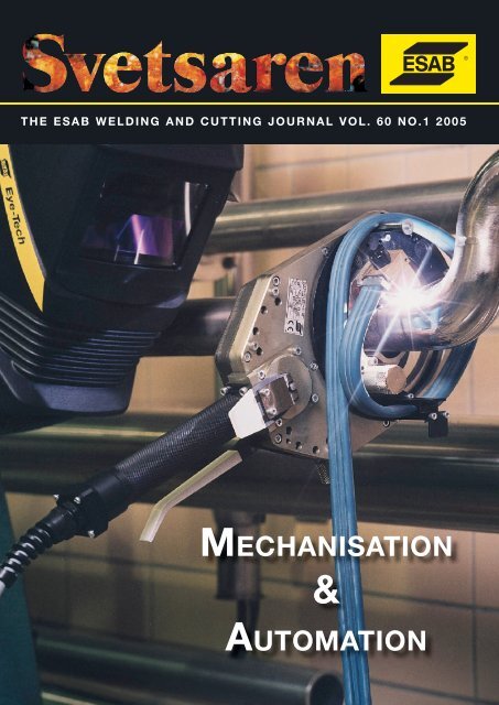
THE ESAB WELDING AND CUTTING JOURNAL VOL. 60 NO.1 2005<strong>MECHANISATION</strong>&<strong>AUTOMATION</strong>
THE ESAB WELDING AND CUTTING JOURNAL VOL. 60 NO. 1 2005Articles in Svetsaren may be reproduced without permission but withan acknowledgement to <strong>Esab</strong>.PublisherJohan ElvanderEditorBen AltemühlEditorial committeeBjörn Torstensson, Johnny Sundin, Bertil Pekkari, Lars-Erik Stridh, Dave Meyer, Tony Anderson,Peter Budai, Soeren Carlsson, Klaus BlomeAddressSvetsaren, ESAB AB, Marketing Communicationc/o P.O. Kernkade 8 3542 CH Utrecht, The NetherlandsInternet addresshttp://www.esab.comE-mail: info@esab.sePrinted in The Netherlands by True ColoursOrbital TIG welding - a great way to joinpipes. See page 3 for full information onthe ESAB product range and usage.Contents Vol. 60 No. 1 2005367111318Orbital TIG – a great way to join pipes.ESAB supplies a complete range of orbital TIGequipmentfor the mechanised welding of tubes.ESAB Welding Process Center facilitiesimproved with new location.New laser-hybrid equipment installed.Light mechanisation - easy andcost-efficient with ESAB.The “mechanical or cold hand” can withstand ahigher current and can move faster than the handof a human welder. ESAB supplies specialisedequipment and dedicated consumables.Railtrac flexible tool for Dutchpipeline constructor NACAP.Dutch pipeline layer NACAP B.V, in Eelde, TheNetherlands, developed a flexible method for thewelding of pipelines on land.Submerged arc welding of steelsfor offshore wind towers.Production economy makes high demands on thedeposition rates of welding processes.OK Flux 10.72 is a new flux for submerged arcwelding with excellent weldability and good weldmetal toughness at - 50ºC.Permanova’s seam tracking laser welding tool.This article reviews the seam tracking featureof the Permanova WT03 laser welding tool, anessential component of the laser-hybrid weldingsystems supplied by ESAB.2123273134Retrofitting of automatic welding systems.The upgrading of welding equipment with moderncomponents, can be a cost-effective alternative toinvestment in new equipment.Mechanised welding of pipelines.The article looks at the different approaches tomechanised pipeline welding and their implicationsin different parts of the world.Cutting technology in shipbuilding.The article describes the latest trends in cutting technologyfor shipbuilding. Cutting speed and bevelquality, and their effects on fabrication are reviewedfor various cutting methods.Improved productivity in automatedaluminium welding fabrication.The successful use of the AlumaPak bulk drumin the US market has led ESAB to introduce thedrum into the European and North American marketsunder the ESAB brand name of Marathon Pac.Product news.• 9% Ni steel and Aristo SuperPulse.• ESAB versatile in robotic welding.• NOMAD finalised.• ESAB high purity consumables forwelding creep resisting steels.• OrigoMig 405 welding package.• OrigoMag C150/C170/C200/C250• COMBIREX CXL-P- CNC cutting machine.
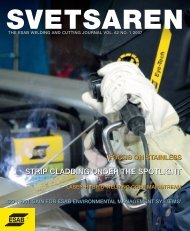
Orbital-TIG – a great wayto join pipesBy: Juha Lukkari, ESAB Oy, Finland.ESAB supplies a complete range of orbital TIG-equipment – including power sourcesand weld monitoring programmes - for the mechanised welding of pipes.Why mechanisation?Although pipes have been welded using mechanisedsystems since the 1960’s, the TIG-process still accountsfor a considerable amount of manual welding. Yet, thereare many good reasons to explore the use of orbital TIGweldingfor applications ranging from single-run weldingof thin-walled stainless pipes to multi-run welding ofthick-walled pipes, and even narrow-gap welding:• Young welders are difficult to recruit.• Operator ergonomics are improved significantly.• Remote control and video control options.• Increased duty cycle - so higher productivity.• Welding procedures repeatable - resulting in aconsistent weld quality.• Good control over heat input.• Equipment available for use “on site”.Stationary vs. orbitalThere are two main catagories of mechanised weldingsystems:• Stationary: the welding head has a fixed positionwhile the pipe rotates.• Orbital: the pipe has a fixed horizontal or verticalposition while the welding head rotates.Orbital-TIG clamp-on weldersClamp-on pipe welding tools are used in orbital weldingof small and medium-sized pipes, see figures 1 and 2.The tools can also be equipped with a wire feeder. Themaximum pipe diameter that can be handled is around200 mm. Tools bigger than this are impractical andunwieldy. The same type of welding tool can be used toweld pipes within a specific diameter range. The PRB/PRC clamp-on welding tools, for example, cover thediameter ranges 17-49 mm, 33-90 mm and 60-170 mm.Normally, pipe standards are taken into considerationwhile designing welding heads, in order to make theFigure 1. Three PRB welding tools for pipe diametersØ 17-170 mm. They are compact welding heads witha unique pincer action. The head is positioned andsecured around the pipe in seconds.Svetsaren no. 1 • 2005 • 3
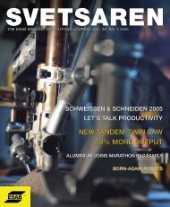
scope of a single welding tool relatively broad.The clamp-on tool is locked onto the pipe in the weldingposition by a single movement of the hand, using the“self-locking pliers” principle. PRC welding tools canalso be provided with the AVC function (AutomaticVoltage Control of the arc length) and with a weavingaction mechanism - both needed in the multi-run weldingof thick-walled pipes.Clamp-on pipe welding tools can be either open (opentools) or enclosed (closed tools). Enclosed heads coverthe entire weld area within a space filled with shieldinggas, figure 3. This is to prevent the hot weld zone fromoxydation. The weld surface is protected in the same wayas the root of a stainless pipe weld is protected by backinggas. Enclosed tools are used in particular for weldsrequiring extreme purity, such as pipes used in thepharmaceutical industry or titanium pipes.For pipe diameters above 170 mm, orbital welding canFigure 2. Three PRC welding tools for pipe diameters Ø 17-170mm. This onward development of the PRB head features wea vingand arc voltage control, providing higher productivity and betterweld quality, especially with thick-walled tubes.Figure 3. Three enclosed PRH welding tools for pipe diametersØ 3-76 mm. The rotating part and the tungsten electrodeare enclosed by a gas chamber formed by the outer casing.This water-cooled head is designed for welding thin-walledstainless steel and titanium tubes.be achieved by using a welding carriage that travels thecircumference of the pipe along a track, figure 4. ESAB’sPRD 100 carriage is particularly low (75 mm), whichmeans that it will fit into confined spaces. Welding headsfor narrow-gap welding of thick-walled pipes are alsoavailable (to be discussed later).Mechanisation requires accuracyMechanised welding requires a greater accuracy ofgroove preparation and fit-up than manual welding -where the welder can use his skills to “patch-up” anyshortcomings. In orbital welding, the machine only doeswhat it has been programmed to do, without compensatingfor joint irregularities. The time spent on machining ajoint preparation with adequate precision, therefore, oftenFigure 4. PRD 100 carriage.Figure 5. Pipe groove cutter MF3i for pipe diametersØ 25-152 mm.exceeds the actual welding time. Efficient machiningtools are available from ESAB, figure 5.Also narrow gap weldingNarrow-gap welding with orbital TIG welders and specialwelding heads is a process adopted over recent years,figure 6. By narrowing the cross section of the joint, the4 • Svetsaren no. 1 • 2005
joint volume is reduced by a factor of 2-3, depending onthe wall thickness, figure 7. The bevel angle of a conventionalU-groove is 10-20º, but in narrow-gap welding it is amere 2-6º. A narrow-gap weld is usually made by welding“bead-on-bead” - so one run per layer.Power required as wellPower sources for orbital TIG welding come in a varietyof sizes and models, figure 8. The Weldoc WMS 4000welding monitoring system can be connected to all ofthem. When using a carriage (PRD) or a welding head(PRC) equipped with the AVC function and weavingmechanism, Protig 450 should be the power source.Welding monitored by cameraA small camera installed in the welding carriage enablesthe operator to monitor the welding process, figure 9.This significantly eases the task of monitoring weldingand improves management of the process and ergonomicsof the operator.Figure 6. Narrow-gap PRB welding head for pipe wall thicknessup to Ø 80 mm. Inset shows a typical weld cross section instainless steel AISI 304.Weld sequences monitored and documentedToday, many industries require highly detailed verification,reporting and documentation of mechanised weldingsequences.This is achieved by connecting a PC with a monitoringprogramme to the programmable power sources, figure10. The welding parameters are measured at intervalsas short as 0.5 seconds and displayed in real time. Thecapacity is large enough to monitor and register scores ofparameters. When the welding is completed, the measuredwelding parameters are obtained as output.After welding, it is easy to compare actual values with setvalues and pinpoint any deviations. The parameters canalso be allocated limit values to facilitate the monitoringof any deviations with respect to the welding procedurespecification (WPS).Figure 7. Comparison of cross-sectional areas of pipe weldinggrooves. Groove dimensions: normal U (included angle 30°,radius 3 mm and root face 2 mm) and narrow-gap groove(included angle 4 degrees, radius 3 mm and root face 2 mm).Figure 8. Power sources for TIG welding: Prowelder 160, 250 and 320 and Protig 450.Svetsaren no. 1 • 2005 • 5
Figure 9. Orbital narrow-gapwelding. The operator controlsthe welding process via amonitor receiving the imagefrom a camera mounted ontothe welding head.Figure 10. Monitoring of welding parameters using theWeldoc WMS 4000 computer programme.A compact printer is also available for documentation,for example, printing of welding current, voltage, travelspeed and wire feed speed, measured sector-specificallyand bead-specifically during the welding.Operators need to be qualified!Users of mechanised welding systems must be qualifiedto a special standard, EN 1418*, and not only to EN287which is the qualification standard for manual welders. InEN 1418, the user is referred to as the ‘operator’ - not the‘welder’. Note that the operators standard also includes amandatory “theory” test to verify the operator’s knowledgeof the functioning of the welding station.* EN 1418: Welding personnel - Approval testing of weldingoperators for fusion welding and resistance weldsetters for fully mechanised and automatic weldingof metallic materials.About the authorJuha Lukkari joined ESAB OY in Finland in 1974 aftergraduating from the Helsinki University of Technology. Hehas held several positions and is currently head of technicalcustomer service.For more information contact: juha.lukkari@esab.fiESAB Welding Process Centre facilitiesimproved with new locationESAB’s Process Center in Gothenburg– the company’s primary center forapplication research and training inEurope – has moved to a new locationon the same premises.The move, to a more convenientposition closer to the welding laboratories,had been long considered,but became necessary with thearrival of the new laser-hybridcell which required considerablespace. All diciplines involved inapplication research and trainingnow enjoy short communicationlines and the new lay-out ensures amore efficient use of the facility.For more information contact:larserik.stridh@esab.seThe laser-hybrid installation at the new Process Centre in Gothenburg, Sweden.6 • Svetsaren no. 1 • 2005
Light mechanisation.Easy and cost-efficient with ESABBy: Juha Lukkari, ESAB Oy, Finland.Light mechanisation of welding involves the use of small, easy to use, and comparativelylow-priced equipment to move the welding gun, generally making use of small tractorsand carriers on rails that can be connected directly to existing MIG/MAG power sources.ESAB supplies a full range of equipment and consumables.Also see page 11 for a story on the Dutch pipeline fabricator, NACAP, applying lightmechanisation on a section of Europipe.Why light mechanisation?The most obvious reason for light mechanisation is toobtain a higher productivity in the form of more weldedmeters per time unit. The duty cycle is higher than inmanual welding and the travel speeds and depositionrates obtained are also greater.A typical application is fillet welding in PB position.A human welder will experience great difficulties incontinuously handling a welding gun at travel speedsin excess of 50 cm/min, but a small tractor can easilyachieve 100 cm/min or more. In manual welding, theendurable welding current limit is perhaps about 300 A,but machines can easily withstand 300-350 A.As a result, the deposition rate when using, forexample, metal-cored wire OK Tubrod 14.12 (AWSE70C-6M, EN T 42 2 M M 1 H10), increases to as highas 6-8 kg/h.Light mechanisation holds more advantages than ahigher productivity, however, that can individually, ortogether, justify an often modest investment.• Improved work conditions and safety. The physicallystrenuous work is transferred to the machine and thewelder is charged with setting and controlling theprocess - enjoying ergonomically improved conditions.• The quality of the weld is often better and moreconsistent. Optimal welding parameters are maintainedthroughout the entire length of the weld, and starts andstops - always potential defect points - are avoided.• Improved weld appearance. The appearance of, forexample, mechanised welded stainless steel welds,can be so good that architects even utilise them as acosmetic feature on the outside of fancy office buildings- actually the case in Helsinki !Design welds with eye to mechanisationTo enable the welding to be mechanised, it must betaken into consideration at the construction design stage.Long straight welds without obstacles along the way areeasy to mechanise. Fillet welds are always more attractivethan butt welds from the mechanisation point of view.Svetsaren no. 1 • 2005 • 7
Skilled operatorMechanisation can never be successful without thesupervision of an experienced operator. He must set theappropriate welding parameters, recognise when theyneed to be adjusted and control the overall process.This calls for an experienced manual welder with expertknowledge.Selection of cored wiresLight mechanisation of MIG/MAG welding is primarilybased on the use of cored wires. The choice of type ofcored wire depends mainly on the welding position andon the required impact strength.Impact toughness: -20ºC• PB-position welding:metal-cored wire OK Tubrod 14.12 (AWS E70C-6M,EN T 42 2 M M 1 H10).• Vertical welding (PF):all-positional rutile flux-cored wire OK Tubrod 15.14,OK Tubrod15.15, FILARC PZ6113 (AWS E71T-1/ENT 46 2 P M 2 H10).• Horizontal-vertical welding (PC):Either cored wire type.Impact toughness: -40ºC• PB-position welding:metal-cored wire OK Tubrod 14.05 (AWS E70C-G/EN T 42 4 Z M M 2 H10).• Vertical welding (PF):all-positional rutile flux-cored wire OK Tubrod 15.17,PZ6138 (AWS E81T1-Ni1/En T 46 3 1Ni P C 2 H5).• Horizontal-vertical welding (PC):Either cored wire type.Light-mechanisation equipmentESAB equipment for light-mechanisation breaks down intwo categories:carriers on rails:• Railtrac 1000 W (Figure 1).• Railtrac 1000 FW.and small tractors:• Miggytrac 1000 (Figure 2).• Miggytrac 2000.• Miggytrac 3000.Typical applicationsFillet weld, PB position.A typical application for a tractor is performing filletwelds in PB-position. The productivity achieved easilydoubles that of manual welding, see table 1. Metal-coredwire OK Tubrod 14.12 is exploited to its maximum.Figure 1. Railtrac 1000.a-size(mm)Weldingcurrent: DC-(A)Arcvoltage(V)Figure 2. Miggytrac 1000.Weldingspeed(cm/min)3.5 320 32 100 164 330 32 90 175 340 33 65 187 340 34 35 19Wirefeed(m/min)Table 1. Fillet welding in PB-position using metal-cored wireOK Tubrod 14.12-1.2mm.Butt weld, PF position.A typical application for a carriage on rails is verticalwelding (PF), which can be either butt welding or filletwelding. Roots of butt welds can be made with ceramicweld metal support.• Vertical welding (PF).• Plate thickness: 14 mm.• Groove and run sequence: 45° V-joint, root pass,two filler layers.• Weld metal support: Ceramic backing.• All-positional rutile flux-cored wire: PZ6113 – 1.4mm.• Shielding gas: 75%Ar+25%CO 2.• 1st pass: 160-180 A, 22-23 V, 10-12 cm/min.• 2nd pass: 180-190 A, 24-25 V, 16-18 cm/min.• 3rd pass: 210-220 A, 24-25 V, 14-15 cm/min.• Weaving and edge stopping time: Depends on actualgroove width.• Impact toughness (weld metal):• -20ºC: 27, 75, 73 / av. 58 J.• -40ºC: 60, 50, 46 / av. 52 J.8 • Svetsaren no. 1 • 2005
Figure 4. Manufacturing of stainless steel facade beams for alarge office building in which the architect would most probablynot have accepted manual welding. Fillet welds in PBposition. Use of Miggytrac and rutile flux-cored wire: OKTubrod 14.31.Figure 3: Horizontal-vertical pipe weld.Pipe weldsWhen welding large-diameter pipes, eg, natural gas pipes,two rails bent to a specified diameter can be used in weldingby mounting them around the pipe and fastening them toone another to form a continuous track around the pipe.Example:• Pipe steel: X65.• Pipe diameter: 800 mm.• Wall thickness: 12 mm.• Groove and run sequence: V-joint, 60-70°.• Shielding gas: 75%Ar+25%CO 2.• Root pass: Various options:• Manually from top down (PG) using metal-cored wireOK Tubrod 14.12.• Manually using basic or cellulosic electrode.• Fill-up run and final run: No’s 2 and 3:• Using carrier upwards (PF), 6 -> 12 o’clock• All-positional rutile flux-cored wire: OK Tubrod 15.14• 1.2 mm, 180-200 A, 23-24 V, 10-20 cm/min.Figure 5. Vertical-up welding on the inside of a debarkingdrum. Railtrac and all-positional rutile flux-cored wire: OKTubrod 15.15.PilesThe joint welds in pile pipes to be driven into the groundcan also be mechanised by using rails bent to matchspecified diameters. Fixed steel backing is often used atthe root side.• Pipe diameter: 800 mm.• Wall thickness: 12 mm.• Backing: Fixed steel bar.• Groove and run sequence: see figure 3.• Welding position: horizontal-vertical (PC).• Metal-cored wire: OK Tubrod 14.12 – 1.2mm.• Shielding gas: 75%Ar+25%CO 2.• Passes, 6–7 in number: 180-210 A, 25-30 V,45-55 cm/min.• Mechanisation with Railtrac.Figure 6. Horizontal-vertical welding of the main supporter ofa gantry crane. Railtrac and metal-cored wire: PZ6105R.Svetsaren no. 1 • 2005 • 9
Industrial applicationsThe figures 4 to 9 show projects in which light mechanisationwas used. They are all based on the use of coredwire. Also refer to page 21, reviewing a recent pipelineproject in the Netherlands using Railtrac equipment andcored wire.Figure 8. Welding ofsteel fender piles for asuspension bridge inArgentina. Railtrac andbasic flux-cored wireOK Tubrod 15.27. SeeSvetsaren 2/2003 forthe full story.About the authorFigure 7. Welding of the suspended roof structure of theBenfica stadium in Lisbon. Railtrac and structural all-positionflux-cored wire PZ6113. See Svetsaren 2/2003 for the full story.Juha Lukkari joined ESAB OY in Finland, in 1974, aftergraduating from the Helsinki University of Technology. Hehas held several positions in the company and is currentlyhead of Technical Customer Service.For more information contact: juha.lukkari@esab.fiDoor opening contract in ChinaIn November 2004, ESAB in Laxå, Sweden, sold its firstflash butt chain welding machine to Zhang Jia Kou CoalMining Machinery Ltd Co - China’s largest and mostmodern coal mining chain and equipment producer. Thecompany is a part of China Coal Mining EngineeringEquipment Import & Export Co.The machine is designed for different kinds of chains;from 30 mm to 60 mm bar diameter. The basic chainsare collector links for lifting chains and large coal miningchains, some with one forged and one welded link insuccession.The machine is based on the SVU - series of flash butt weldingmachines, upgraded with a higher clamping force andsome additional useful functions. The machine featuresan automatic setting to obtain a constant secondary voltagewith mains fluctuating +/-15%. Also, the machine adapts tothe temperature of the link (from T room up to 800° C).PRODUCT DATA:Upset force:Clamping force:Transformers (AC):Weight:350 kN480 kN2x 250 kVA12,800 kg.For more information contact:sylve.antonsson@esab.seESAB supplies rail welding equipment to India and CroatiaESAB in Laxå, Sweden has recentlydelivered two automatic flash buttwelding machines for rails; designedto produce long, high quality rails ofall types.The deliveries - through Geismar,France - were to the Bhilai SteelTECHNICAL DATA:Clamping force:Upset force:Max current for standard rail (UIC 60):Weight:Plant in India and HZ- Infrastrukturain Croatia. The Bhilai machine is partof a complete rail welding factorysupplied by Geismar; the Croatiancontract is a single machine order.The ZFR 11 GC 6T machines havebuilt-in trimming units, and include196 Metric tons96 Metric tons70.000 Amps38.000 kgscompressor-type cooling units andexhaust systems. Other featuresinclude PC control with forces andspeeds controlled in closed loopsvia sensors and a high responseproportional valve, and full loggingof all welding parameters andthe most recent 1000 alarms. Thewelding process uses DC- currentwhich gives equal load on the threephases.For more information contact:sylve.antonsson@esab.se10 • Svetsaren no. 1 • 2005
Railtrac flexible tool for Dutchpipeline constructor NACAPBy: Frits Woldinga, NACAP B.V. , The Netherlands and Sjabbe Datema, ESAB Nederland B.V.International pipeline contractor NACAP B.V, with its head office in Eelde, The Netherlands,developed a flexible method for the welding of pipelines on land, utilising two ESABRailtrac FW 1000 welding tractors and OK Tubrod 15.09 flux-cored wire. The advantagescompared with commonly used mechanised pipeline welding systems are found in a lowerinvestment and shorter set-up times before welding. The new method was successfullyapplied on a 17 km pipeline crossing the northern part of the Netherlands.The pipeline, for which the equipment was developed,is in X70 grade steel with a diameter of 42 inch and anominal wall thickness of 14.0 mm. Sections to passunder canals are 16.4 or 19.9 mm in thickness. Weldmetal toughness requirements are min. 40J at -40°C.NACAP developed the system in-house and afterextensive testing official welding procedure qualificationswere made. The equipment comprises some features thatare non-standard to the ESAB equipment and the designincludes an extremely light welding tent.The method uses two Railtrac FW 1000 tractorssimultaneously walking the pipe circumference from 6‘o clock to 12 ‘o clock; clockwise and counter clockwise.The diameter of pipelines in general are smaller thanthe type of applications for which Railtrac has beendeveloped, having originated from shipbuilding practice.The aluminium rail coming with the equipment wouldrequire more fixtures around the pipe circumferenceto avoid buckling when tension is applied. Even theslightest unroundness in the orbit of the tractor wouldhave a negative effect on the weld quality. Instead ofadapting the standard ESAB rail, NACAP decided todevelop its own, more rigid rail equipped with fastcoupling gear.The 2nd adaptation to the equipment, done by ESABat the request of NACAP, involved a change from onedrive wheel to two drive wheels, one on either side of thetractor. This increased the stability of the tractor whiletravelling the pipe circumference at a high speed.The system uses two ESAB AristoMig 400winverter controlled power sources with Aristofeedwire feed units.Figure 1: Railtrac at work.First the root pass, hot pass and two filler layers aredeposited vertically down with MMA with cellulosicelectrodes. The subsequent filling is done with Railtracusing OK Tubrod 15.09 all-position rutile cored-wirewelded under Ar/CO 2mixed gas.OK Tubrod 15.09 has a fast freezing slag that supportsthe weld pool well in positional welding at very highdeposition rates. The slag easily releases leaving behind aclean weld for subsequent passes. One parameter settingcould be applied for all beads in this kind of application.NACAP preferred to use three optimised parametersettings while travelling from 6 to 12 ‘o clock.Svetsaren no. 1 • 2005 • 11
Figure 2: The welding tent, including equipment, is easilymoved to the next weld, helped by its weight of just 500kg.The EN classification of OK Tubrod 15.09, T 69 4 ZP M 2 H5, indicates that it is a consumable for highstrength steel and that the weld metal hydrogen contentfalls within the lowest EN class, H5. This allows lowerpreheat temperatures than consumables with a higherhydrogen content, such as cellulosic electrodes. Thiswas visible in the welding procedure for the completeweld. During MMA welding a preheat temperature of150 ºC was maintained, whereas 100ºC was sufficientfor FCAW.The deposition rate that is obtained with FCAW isattractive. The time needed to complete one weld,installation and de-installation included is roughly onehour. Fast transportation to the next weld is aided bythe light weight of the welding tent; 500kg equipmentincluded. To NACAP, this fast task force is a welcomeasset to the automatic welding systems they utilise allover the world, and increased usage of this system isforeseen. An additional 11 km pipeline in the northernpart of The Netherlands is already planned.Figure 3: Weld appearance of the cap layer showing thetypical smooth “rutile” weld metal.About The AuthorsFrits Woldinga is Welding Technologist at NACAP, TheNetherlands. Sjabbe Datema is Sales Engineer at ESABB.V., The Netherlands.For more information contact: sjabbe.datema@esab.nl12 • Svetsaren no. 1 • 2005
Submerged arc welding of steelsfor offshore wind towersThe German renewable energy industry goes offshoreBy Rolf Paschold and Dirk Dirksen, ESAB GmbH, Solingen.Rough maritime conditions place high loadsand stresses on offshore wind turbines. Forthis reason, the mechanical characteristicsof steels and weld metals are very high.Steels with yield strength of 355 MPa arecommonly used and high wall thicknessesresult in higher weld joint volumes.Production economy makes high demandson the deposition rates of applicablewelding processes. ESAB has introduced,OK Flux 10.72, a new flux for submergedarc welding with excellent weldability andgood weld metal toughness at – 50ºC.The results of the highly productive twin-arctandem welding system are discussed.IntroductionWind at sea is stronger than on land, resulting in higherwind turbine efficiency. After erection, testing andimplementation of single offshore wind turbines, complexoffshore wind parks are now established, mainly inScandinavia. Several areas in the North and Baltic Seasare also being considered. Offshore turbines up to 5 MWare planned and the combined capacity in parks adds upto 1,500 MW, with towers of more than 100 m high.Requirements for offshore wind turbinesBefore installing wind turbines, environmental issues andrisks for and from navigation are considered. These studiesare important not only for the owners and insurancecompanies, but also for the manufacturers of offshoreenergy equipment. Some results from the technical andrisk analysis are leading to special requirements for theproduction and erection of offshore turbines. Typicalrisks for foundations and towers include:Figure 1. Examples of principles for foundations: from left to rightgravity foundation, monopile, tripod. [Source: www.sky2000.info]Figure 2. Tension leg offshore windturbine [1].Svetsaren no. 1 • 2005 • 13
Figure 3. SAW-Tandem-twin process for longitudinal welding in wind tower production.• Collision by ships.• Tides, streaming and heavy swelling.(especially on the North Sea).• Ice drifting (especially on the Baltic Sea).• Squalls and Hurricanes.Foundations for offshore wind turbinesSeveral foundation concepts are under consideration,including monopiles, gravity solutions, tripods, jacketfoundations and others (Fig. 1). Some of them are alreadyin use or in test phases [2].For single turbines and wind parks (eg, Horns Reef,Denmark) monopiles are preferred for water depth up to25 m. If depth and sea ground conditions allow, piles arerammed deeply into the ground. With increasing depth,the tripod foundation is of interest. Common to all ofthese foundation options is some degree of constructionfrom pipe work. The production of such “pipes” is basedon the forming and welding of thick plates.When the sea bed is too firm for piles, floating tension legturbines may offer the best solution (Fig.2) [1].Requirements for steels and welded jointsIf the service life time of an offshore turbine is about 20years, this could be equivalent to about 10 9 load cycles.The fatigue load requires welded joints to be preferablyplaced in areas of low stress and to be notch-free [2].Monopiles typically have a diameter above 4 m and alength of more than 30 m. They are made from 40 – 70mm thick plates of a width of 2 – 3 m. For comparisononshore towers have a wall thickness up to 45 mm at thebottom and about 10 – 15 mm at the top.For mild steels, the carbon equivalent (CE or CEV) usuallyincreases with increasing wall thickness, the greaterthickness causing higher cooling rates during welding.For this reason, appropriate measures have to be taken toavoid hardening of the structure in the heat affected zone(HAZ) and cold cracking, such as [3, 4]:• Preheating.• Sufficient heat input.• Multi-layer welding.• Low hydrogen content of welding consumables.According to Germanischer Lloyd [2] structural parts areclassified into main groups, depending on the type andamount of stresses and loads:• Special Structural Members(Highly stressed, eg, flanges).• Primary Structural Members(normally stressed parts, eg, tower wall plates).• Secondary Structural Members(low stressed, eg, lamp holder).S355J2G3 is the most commonly used steel for14 • Svetsaren no. 1 • 2005
onshore wind towers, whereas the toughness demandsin offshore deployment necessitate fine grained steelswith higher impact toughness.Steels for “Special Structural Members“ are to be of highquality with low impurities of sulphur and hydrogen andof guaranteed adequate through-thickness ductility. Theyield strength class is 275 MPa and above, good Charpy-Vvalues are demanded for all regions of the welded joint tomin. –40°C. Additionally CTOD-testing can be required.The following steels according to EN 10225 [5] aresuggested as appropriate:S355G8+M S420G2+Q S460G2+Q S355G10+MS355G8+N S420G2+M S460G2+M S355G10+NThe requirements for steels for “Primary StructuralMembers“ are rather similar, except the improvedthrough-thickness properties. The European standardlimits the carbon content to C ≤ 0.14% and the carbonequivalent to CEV ≤ 0.43%; GL-rules contain verysimilar limits. The EN-standard requires Charpy-V valuesof ≥ 50 J at –40°C, GL-rules: ≥ 34 J longitudinal and≥ 24 J transversal. The recommended steels according toEN 10225 [5] are:S355G7+M S420G1+Q S460G1+Q S355G9+MS355G7+N S420G1+M S460G1+M S355G9+NFor lower plate thickness between 25 and 50 mm theGL-rules allow the use of simple steels such as:S355G6+M and S355G3+N acc. to EN 10225,S355J2G3 acc. EN 10025 (with special certification).Requirements for fabricatorsAccording to EN 10225, the steel producer has to providecustomers with information about weldability, if thethickness is t ≥ 40 mm. The article “18 – additionalrequirements” is about certification of weldability testsaccording to customer wishes, to prove the suitabilityof the delivered batch for meeting the requirements afterwelding with or without post weld heat treatment (PWHT).In addition, the tower producers set strict limits on tolerancesin plate thickness, surface quality and joint preparation.Withincreasing strength and toughness, heat input and coolingrates (preheat and interpass temperatures) as well as energyper unit of length, become more important. According to thestandards and rules, suppliers and producers have to meetseveral demands [2]. The fabricator should only use weldingconsumables which have proven to have constantlyhigh CTOD-values at -10°C.Welding fabrication is based on welding procedurequalifications (WPQs) in accordance with EN 288-3,including details such as:• Preheat temperature.• Maximum interpass temperature.• Welding process.• Heat input.• Welding position.• Welding consumable.WPQs are commonly made in all cases and have to beavailable for the purchaser of the wind turbine module.Welding of a WPQ is essential, especially when weldingwithout PWHT, which fabricators aim for. Usually PWHT(stress relieving) is demanded for thick walled steelsin conditions +N (normalised) and +M (temperaturecontrolled milling) in the offshore industry. This is validfor steels t ≥ 40 mm according to EN 10255 and t ≥ 50mm referring to GL-rules.To allow welding without an expansive PWHT, factors tobe proven include:• Certified weldability of the steel.• Mastery of welding procedures, shown by WPQ’s.• CTOD-testing acc. to EN 10225, appendix E,or purchasing the plates acc. to “Additionalrequirements 18” acc. to EN 10225.Figure 4. SAW-welding of the first layer with the first weldinghead only (Twin-arc).Figure 5. Tandem-Twin-welding with four wires Ø2.5 mm(H.I. 2.7 kJ/mm, deposition rate 28 kg/h at 100% duty cycle)Svetsaren no. 1 • 2005 • 15
MaterialHeatDim.mm C Si Mn P S N Al Cu Cr Ni Ti Nb CEVS355G8+NEN 1022509639 50 0.14 0.20 1.47 0.014 0.004 0.003 0.042 0.07 0.05 0.19 0.003 0.025 0.41Autrod 12.22EN 756: S2SiPV-403028048ø2.5 0.107 0.19 0.91 0.013 0.012 0 0.001 0.069 0.05 0.03 0.001 0.003Weld metalEN 756:S 38 5 AB S2Si0.083 0.33 1.62 0.015 0.007 0.07Table 1: Chemical composition of the base metal, SAW-wire and the weld metal, as well as CEV acc. to EN 10225Welding productionThe tough requirements regarding the quality and mechanicalproperties of the welded joints seem to be in conflictwith productivity. However, submerged arc welding iscapable of combining high quality with high depositionrates and is, therefore, the first choice for wind turbinetowers and foundations. Process variants with more thanone wire electrode become more important with increasingthickness and joint volumes, because they offer a furtherincrease in deposition rate. One development is theTandem-Twin-process (Fig. 3) with four wire electrodes,capable of depositing more than 30 kg/h of weld metal(based on 100% duty cycle).With high welding currents (more than 1600A) for highdeposition rates, the heat input has to be in focus. Meetingthe requirements for quality, the heat input and weld beadthickness have to be limited in multi-layer technique, sotravel speed is increased to values above 100 cm/min.This takes advantage of the tempering effects of followingbeads, which has a positive influence on the mechanicalproperties in all regions of the joint, especially on thetoughness at -40°C and below.The first choice of wire is OK Autrod 12.22 (EN 756– S2Si). A higher Si-content is of positive influence ondeoxidization and slag detachability. In addition, the wirehas very low content of impurity elements that have animpact on toughness.Testing Position BM HAZ WMLowest value HV10 154 170 178Average HV10 157 211 193Highest value HV10 161 260 205Heat InputHeat input is of great importance. If it is too low, theHAZ hardens and becomes susceptible to cold cracks.If it is too high, the grain growth in the HAZ affects thetoughness. The heat input during test welding has been1.9 kJ/mm for the first (Fig. 4) and 2.7 kJ/cm for thefollowing layers.Welding Procedure Testing with S355G8+NBase materialWelding tests have been carried out on plates S355G8+Nacc. to EN 10225 (similar to S355NL / EN 10113-2, butwith guaranteed through-thickness ductility). A meltingheat reaching the maximum acceptable carbon content ofC = 0.14% has been chosen, see table 1.Wire and fluxTo increase operating efficiency of the multi-wire processand meet the tough mechanical requirements, a newlydeveloped flux is suggested, featuring high currentcarryingcapacity, good high-speed behaviour and goodslag detachability in relatively narrow joints.The new aluminate-basic welding flux OK Flux 10.72(EN 760 - SA AB 1 57 AC H5) has been adapted to meetthe requirements of European wind energy producers,producing a weld metal with toughness down to -50°C.Figure 6: Crosssection of thewelded joint,t = 50 mm.To start with, the preheating temperature was 125°C, themaximum interpass temperature was limited to 250°C.After the fourth weld bead, the working temperaturewas between 160 and 180°C. However, in production onlarger workpieces, the temperature has to be maintainedby heating.As commonly used in wind tower production, the includedangle of the V-groove was 50+5°, the land 3–5 mm. Tostart with, a backing pass was produced by MAG-welding,placed on the back side and ground off after turning.Including the capping passes, 31 beads have been weldedwith the submerged arc process (Fig. 5, 6).16 • Svetsaren no. 1 • 2005
Results of mechanical testingThe welded plate was not heat treated, having in mind, thatalmost all producers will use the qualification proceduresby CTOD-testing at -10 degrees C instead of heat treatinglater on.• Hardness Values:The hardness testing HV10 was executed on the crosssection, containing unaffected base material (BM), heataffected zone (HAZ) and weld metal (WM).Referring to EN 10225 (E.4) the acceptable hardness islimited to 325 HV10.• Tensile TestA transverse flat tensile specimen showed a tensilestrength of 520 MPa, required strength acc. to EN 10225is Rm = 470 – 630 MPa. The fracture occurred in theunaffected base material.• Impact TestFor steel grades S355, EN 10255 (E.4) requires a minimumaverage of 36 J and a minimum single value of 26 Jat -40°C. Test results of impact (Charpy-V) acc. to EN875, HAZ:V-NotchPositionTemp.Single ValuesVHT 1/2 -40°C 111 115 112 113VHT 1/20 -40°C 56 41 58 52VHT 1/38 -40°C 64 56 78 66AverageNevertheless, the welding consumables have beenapproved for -50°C, the impact values of the weld metalproduced by TandemTwin-welding are of interest:V-NotchPositionTest-Test-Temp.Single ValuesVWT 0/2 -50°C 113 107 110 110VWT 0/20 -50°C 100 75 55 77VWT 0/38 -50°C 42 66 48 52AverageThe weld metal does fulfil the requirements, even at-50°C. However, there is a visible trend of increasingvalues with decreasing dilution from the base metal.ConclusionsThe welding tests have proven that highly economicalvariants of the SAW process can meet the requirements forquality and mechanical values in the offshore wind powerindustry. The limited investments for increased depositionrates by using Tandem-Twin welding recommend thisprocess variant to wind turbine producers - not only inthe offshore segment.The welding consumables OK Autrod 12.22 and OK Flux10.72 have shown an outstanding welding behaviour andexcellent mechanical values. Temperature controlledmilled (M) steel grades such as S355G8+M will be thepreferred grades for welding production, recommended bylower carbon contents and carbon equivalents to achieve abetter weldability at lower preheat temperatures.References:1. W. Musial and S. Butterfield: Future for Offshore WindEnergy in the United States. Conference paper, EnergyOcean, Palm Beach, Florida, June 29-29, 2004.2. Dalhoff, P., u. a.: Chancen und Grenzen von Mono piles – ErsteErkenntnisse aus dem Forschungsvor ha ben Opti-Pile. 2. TagungOffshore WindEnergie, Hamburg 2003, www.gl-wind.com3. SEW 088 – Schweißgeeignete Feinkornbau stähle. 4. Ausgabe,Verlag Stahleisen mbH, Düsseldorf, Oktober 1993.4. Merkblatt 381 – Schweißen unlegierter und niedriglegierterBaustähle. Stahl-Informations zentrum, Düsseldorf, 1999.5. DIN EN 10225: Schweißgeeignete Baustähle für feststehendeOffshore-Konstruktionen - Technische Lieferbedingungen;Januar 2002.About the authorsDirk Dirksen (Mech. Eng./EWE) is Product & ProjectManager Automation and Engineering for Austria,Switzerland and Germany. He joined ESAB in 1989 and islocated in Solingen, Germany.Rolf Paschold (Mech. Eng./EWE) is Product ManagerWelding Consumables, serving the Austrian, Swiss andGerman markets. He joined ESAB in 1991 and is locatedin Solingen, Germany.For more information contact rolf.paschold@esab.deSvetsaren no. 1 • 2005 • 17
Permanova’s seam trackinglaser welding toolBy: Niklas Wikström and Tore Salmi, Permanova Lasersystem AB, Mölndal, Sweden.State of the art MIG equipment combined with the latest laser technology. Co-operationbetween ESAB and Permanova in laser-hybrid welding brings the best of two worlds together.This article reviews the seamtracking feature of the Permanova WT03 laser welding toolsystem, an essential component of the laser-hybrid welding systems supplied by ESAB.OverviewWeld configurations, overall dimensions and tolerances,and the welding process itself, impose different demandson an automated welding system. In many cases, tolerancesof the parts to be welded, including their positions, areso precise that the weld joint can be found and followedwithout a seam tracking system. Typical cases are machinedcomponents, i.e, rotary (butt) welds for gearbox parts, withrelatively small dimensions, and the joint in a (2D) plane.In such cases, the clamping is typically solved by pressingtogether parts with press fit tolerances.Other cases, for example in car roof welding, are moredifficult. In this typical overlap weld situation, the overallposition of the weld can vary, from car to car, by severalmm in the (3D) space. Usually, it is sufficient to locate thebeginning and/or the end of the weld trajectory with anexternal optical measurement, followed by a correction ofthe robot programme path position. The position sidewaysof the weld is not critical, and the two plates are typicallypressed together with a pneumatically controlled force on aroller, also securing the focus position of the laser beam.Today, the trend in car roof welding is to use an edgeoverlap weld instead, in order to get an efficient sealingand a cosmetically pleasing weld, with less problemsfrom the trapping of vaporised zinc. At the same time,a higher speed is possible without increasing the laserpower, compared with the full overlap weld situation.Inspection of weld quality is also simplified. Typicalwelding speeds are in the range of 4 to 10 m/min. Theseam tracking accuracy has to be better than +/- 0.1 mm.Welding ToolThe standard welding tool includes a press roller withan integrated cross jet for cover slide protection, rotatingcollimation unit, and a Cover Slide Monitor (CSM).The Permanova welding tool has a press roller, wherethe pneumatic pressure can, in principle, be programmedfrom a robot. The force is usually in the range 0 to 500 N.(EPP Valve etc. not included). The collimating f 200optics is water-cooled and has an optical swivel foroptimal access and minimal wear of the fiber. Focussingoptics is f 200 mm (optional 120-250mm).The upper and lower position limits of the pneumaticmotion (usually ±10mm), are monitored by the seamtracking controller and relayed to the robot. The absoluteposition of the motion is also displayed in the softwareand transmitted to the robot - of great assistance duringrobot programming.An integrated crossjet minimises dirt on the cover slideglass and avoids weld spatter on the welded product.The degree of contamination on the cover slide glass ismonitored by the Permanova CSM, mounted on the coverglass holder. Spatter from the welding process depositedon the cover slide surface is optically detected, and smokeand very small particles are thermally detected. Thesesignals are integrated into the seam tracking software,18 • Svetsaren no. 1 • 2005
Figure 1. Welding tool with seam tracking and press device.Nr Item1. Fiber Connection.2. Pivoting Collimating Unit.3. Cable to Electrical Control Cabinet.4. Line Diode 2.5. Welding Nozzle.6. Process Gas Pipe.7. Press Wheel.8. Spatter Screen with Cross Jet.9. Line Diode 1.10. Cover Slide Holder.11. Focusing Unit..12. Beam Bending Cube.13. Pneumatic Couplings.14. CCD Camera.giving the user the opportunity to set warning and alarmlevels. The alarms and warnings are then sent to the robotand/or PLC.Main featuresThis welding tool, Figures 1 and 2, is the result of vastexperience of high power laser beam delivery systems andindustrial installations. The result is a high performance,versatile, compact and reliable modular tool with severalimportant functions, depending on the configuration:• High power handling.• Press roller with adjustable pressure force andintegrated crossjet.• Protective gas supply.• Motorised or manually adjustable (or fixed) focusing unit.• Fiber coupling to Rofin or HAAS.• Fiber coupling unit on rotary optical device allowingfree tilt of the tool with minimal force on the fiberconnector and cabling.• Beam bending cube.• Holder with quick-exchange cover slide holder/glass.• Cover Slide Monitor CSM-OT-S.• Wire feeder, cold wire or hot wire for arc welding (option).• The Motorised or manual Twinspot optic (options).• Seam tracking (option).Seam Tracking FunctionOverviewTo find an edge seam, a sensor is needed. If the seamis measured far from the weld spot, it will be difficultto make sure that the weld spot follows the right path.It will be impossible to reach higher accuracies than thatachieved by the robot - which is not good enough indemanding applications.At the weld spot it is very hot and dirty and one of the fewsensing methods that can be used in this environment isthe triangulation method. A laser line is projected on theedge between the metal sheets to be welded at an angle of30-45° to the normal.This laser diode line, when observed from normal direction,is split up in x-direction (welding direction) becauseof height difference and possible air gap between bothsheets of metal. When observed from above with acamera, the picture looks as shown in the right hand sideof Figure 4.This picture is processed by an image processing PC,which generates a control signal and sends it to theservo unit, which then tilts the optical system around itsrotation axis, thereby directing the laser beam accuratelyat the seam.The seam tracking system will compensate for inaccuraciesin the robot, or the part’s fixture. The robot will followthe nominal trajectory, ie, the trajectory that is correctif the car fixture, car and the robot all were perfect. Theseam tracking system will then correct the deviation fromthis nominal trajectory. By looking closely at the weldspot it is possible to use a simple approach to control theNr Item1. Pivoting Collimating Unit.2. Focusing Unit.3. Welding Nozzle.4. Cover Slide Holder.5. Beam Bending Cube.6. Fiber Connection.Figure 2. The most basic welding tool.Svetsaren no. 1 • 2005 • 19
Figure 4. Diode line splits due to height differencesbetween plates.Figure 3. Principles of operation.beam position. There is usually no need to account forany delay from the measuring spot to the beam position,so no need to rely on the accuracy of the robot, itself.Seam Tracking MovementOn the tool there is a mechanism for moving the beaminto the desired position - a rotating motor with a ballscrew linear guide for very fast and precise movement.This mechanism tilts the optics to move the beam. Tiltingthe optics will make the movement very rigid and precise.At start up, the unit calibrates itself to the nominalposition, found with an inductive sensor. The nominalfactory setting is 4 mm from the pressure wheel. If thenominal position needs to be changed, the sensor can berepositioned. The drive adjusts the beam ± 2 mm fromthe nominal position. The size of this adjustment can beincreased or decreased depending on the process. TheVision Control System will find the seam position. Ifcorrections are needed, the control system sends acorrection signal to the beam moving mechanism.Robot interfaceThe seam tracker control cabinet communicates withthe robot/PLC preferably via a fieldbus interface likeProfibus or Interbus. A digital interface is also availableoffering only the most essential control signals.Additional features• Logfiles of relevant weld data are recorded by theseam tracker and saved for each weld. They are thenkept a user definable amount of time.• Position indicator for the pneumatic motion of the tool.• Possibility to save single pictures or entire videos ofthe welding process.• Covers Slide Monitor alarm, supervision and logging.• Continuously adjustable diode line intensity.• Continuously adjustable welding offset from the edge.- Also adjustable online from the robot during welding.• Automatic logging of the last 20 seconds (possiblymore) frames (pictures) from the welding.- Debug possibility from the logged frames, leads toeasy calibration of the system.• Online graphs showing measured error and regulatedposition.Figure 5. Main window of seam tracking software.• Simple and intuitive operator interface.• All measurement results are presented in mm.• Can be used as an offline measurement system.• Optional remote assistance over internet/modem.SpecificationsWelding tool:Handles 10kW laser powerNA 0.12Rofin or Haas fibersPneumatic motion ±10 mmFocal length f160 or f200mmSeam tracking function:Control sampling frequency and camera speed: 105HzBeam position resolution:±0.002mmSeam measurement±0.01mmControl±0.05mmAbout the authorsNiklas Wikström, MSc. Engineering Physics, isDevelopment Engineer at Permanova, responsible for softwaredevelopment, control engineering and electronics.Tore Salmi, MSc. Engineering Physics, is MarketingManager at Permanova. His responsibilities include thesupply of laser process tools and laser robot fibre systemsto the automotive industry and other high-tech branches.For more information contact: tore.salmi@permanova.se20 • Svetsaren no. 1 • 2005
Retrofitting of automaticwelding SystemsCost-efficiency with state-of-the-art technologyBy: Peter Kjällström and Björn W. Ohlsson, ESAB Automation, Laxå, Sweden.Investment in new automatic welding equipment such as column and boom, gantries andlongitudinal fixtures may be costly and, often, the equipment and systems are planned for aservice life of a decade, or more. However, over such a long period, new products andchanging production targets may cause the original equipment to become quickly outdated.In many cases, upgrading of existing equipment using modern components, is a cost-effectivealternative to investment in new equipment. ESAB offers a retrofit service to fabricators, for itsown arc and flash welding systems - and for equipment from other suppliers.Why retrofit?A major reason for the retrofittingof welding equipment is to avoid thesituation where spare parts can nolonger be purchased. Suppliers tendto maintain stocks of spare parts for acertain period after the equipment hasbeen taken out of production (ESAB,for ten years) but, unavoidably, themoment comes that vital parts are nolonger available. Timely replacementcan prevent this and extend the lifecycle of the equipment.Generally, however, fabricators wantto increase the productivity of weldingsystems by upgrading using the latesttechnology. Column and boom installationsfor submerged arc welding withsingle wire heads, for example, can beequipped with twin-wire heads, tandemheads, or a combination of these, for arelatively low level of investment that issoon paid back by increased productivity.With extreme material thickness, anupgrade with narrow gap submergedarc equipment may be advantageous.Changing products and material thicknessmay also require to retrofit with adifferent process, for instance, replacingMAG welding with SAW.Svetsaren no. 1 • 2005 • 21
Increased qualityBy replacing old control boxes and power sources withthe latest models, during the retrofit, fabricators gain theability to store optimum welding parameters settings,benefit from improved start and stop characteristics, andobtain consistent weld positioning from joint trackingsystems. The result is improved weld quality and a userfriendlysystem.SAW flux dryers and heaters, in combination with anupgraded flux supply system, are another example. Bykeeping flux dry and hot, weld porosity from moistureis prevented and rejects avoided.Retrofit project provides Kvaerner with40% higher welding productivity.Kvaerner Kamfab AB, in Karlstad Sweden, a member ofthe Norwegian Aker Kvaerner Group, specialises in themanufacture of equipment for the chemical pulp industry;from single machines to complete production lines. Thecompany employs some 235 personnel and has a turnoverof around 400 MSEK.ESAB has a long relationship with Kvaerner Kamfab asa supplier of welding equipment and consumables. Overrecent years, ESAB has seen increasing demand fromKvaerner for new equipment and retrofitting of existinginstallations – mainly due to the overwhelming successof Kvaerner’s latest pulp washer, the Compact Press.This high efficiency, high capacity washer, developed byparent company Kvaerner Pulping AB, was introducedin 2000 and, since then, some 50 installations have beendelivered world-wide.With increasing orders and customer demand for shorterdelivery times, Kvaerner made further investment inmachinery, including the retrofitting, by ESAB, oftwo giant column and boom (CaB) installations for thewelding of cylindrical pressure tanks. The tanks, have adiameter of 3m and a length of 18m, and are submergedarc welded both from the inside and from the outside.The welding covers various qualities of stainless steelwith 10-15mm wall thickness. The objective was toincrease the capacity of the installations. The projectwas completed during 2003.Each CaB installation was stripped from its old weldingequipment. The remaining framework was reconditioned,painted and equipped with new welding heads, flux unit,power sources and cabling (see photo). New equipmentincluded:• LAF 1250 power source.• A6S welding head with motor slides and twinwire equipment.• PEH control box.• GMD joint tracking system.• Flux feeding and recovery system with TPCpressure tank.• General overhaul of the system, including newcable chains.Kvaerner calculations indicate that the retrofit has resultedin a 40% increase in productivity, mainly due to:• higher deposition rate due to changing over to twin arcwelding.• less post weld labour due to a n improved weld quality.• reduced downtime.Kvaerner Kamfab, last year, won their most prestigiousorder ever; a complete production line for the biggestpulp mill in China, located in Jian Lin and having acapacity of 3000 tons of pulp a day.About the authorsPeter Kjällström is After Sales Manager and Björn W.Ohlsson is Sales and Marketing Manager Automation atESAB Automation, Laxå, Sweden.For more information contact: peter.kjallstrom@esab.se22 • Svetsaren no. 1 • 2005
Mechanised welding of pipelinesBy: D.J. Widgery, ESAB Group LTD., United Kingdom.This article looks at the different approaches to mechanised pipeline welding and theirimplications in different parts of the world.Systems for the mechanised welding of pipelines havebeen available for more than 40 years and have long beenin exclusive use for offshore pipelines. Yet until recently,they were seen on only a few land pipelines. Now, however,the difficulty and expense of finding sufficiently skilledmanual and semi-automatic pipeline welders has led to arapid growth of mechanised welding onshore. This articlelooks at the different approaches to mechanised pipelinewelding and their implications in different parts of theworld.Early systemsAlmost as soon as CO 2-shielded welding was developed,torches were mounted on carriages for mechanisedcircumferential welding of pipelines. The first crosscountrypipeline to be welded semi-automatically with the CO 2process was laid in the US in 1961, when there were alreadyfive mechanised GMAW systems under development [1],with the first field trial taking place in the same year.Inevitably, Darwinian natural selection took its toll onthe early machines, but it is remarkable how soon thedistinctive features of today’s systems began to crystallise.Development started to diverge along two lines. In one,the welding heads or “bugs” were mounted on bands orchains clamped to the pipe. This became the model forsubsequent onshore systems. The other approach usedan external frame, inside which the welding heads weremounted, and this subsequently found its main applicationon lay barges. Designed for the wide, open spaces of theUSA and USSR, the first machines produced in the 1960sdid not have lightness or compactness as a priority andit is perhaps not surprising that they were not adopted incountries with narrower rights of way and more crossings.1. Drive motor2. Welding wire spool3. Welding head4. Chain5. Guide roll6. Wire feeder7. Wire feederIt was soon discovered that for semi-automatic welding,choosing the right size and type of consumable was thekey to success. There was an initial assumption that thesmaller the wire diameter, the more controllable the arcwould be, and a number of users tried 0.8 mm diameterwires. However, in side-by side tests, welders preferreda 0.9 mm type. It appeared that the lower electricalresistance in the electrode extension (stickout), and hencelower resistive heating, meant that wire burnt off moreslowly at a given current and more heat was availableFigure 1. Tandem mechanised pipe welding system byFalkewitsch, 1961 [1].to melt the parent material and avoid the dreaded “coldlaps” or lack of fusion. Another discovery was that theinclusion of a small amount of titanium in the wirereduced the burn-off rate further and again increased thewelder’s comfort and reduced the defect rate. Comparinga 0.8 mm titanium-free wire with a 0.9 mm titanium-containing one at 200A, 25V it was found that the respec-Svetsaren no. 1 • 2005 • 23
A machine which was to influence a generation of otherswas the PASSO (Progetto Arcos Saipem di SaldaturaOrbitale) equipment. This was particularly light andcompact, and was used from the outset for both onshoreand offshore construction. Its successors finally achieveda breakthrough in Europe when mechanised pipe weldingdisplaced manual welding on the trunklines, even inmountainous regions where the pipe runs through gallerieswith restricted clearance. Mechanised welding wasaccepted early in Canada. In the USA, the home of theprocess, acceptance took longer but this was for social asmuch as for technical reasons.1. Pipe2. Track3. Welding carriage4. Feeding mechanism5. Cassette with wire6. Flux-cored wire7. Forming stideFigure 2. The Styk welding apparatus.tive burn-off rates were 4.10 and 2.99 kg/h. In the firstcase, 33% of the available heat was used to melt the wire;in the second, 24%. Over the next 40 years, thousands ofkilometres of pipeline were laid with 0.9 mm, titanium-bearing wires and they are still very popular today.The job of a pipeline welder is not an easy one andany measure which reduces the extreme concentrationrequired and results in fewer repairs cannot be ignored.However, the great majority of gas-shielded welding onpipelines has been with mechanised systems and it is notat all clear that they benefit from the lower burn-off rateof titanium-alloyed wires. There used to be an advantagearising from the help titanium provided in nucleatingacicular ferrite, but modern steels and wires are so lowin impurities that high toughness can be achieved over arange of microstructures. In today’s mechanised pipelinewelding, both titanium-bearing and titanium-free wiresare in successful use and welding manufacturers havecome to accept the right of users to make their ownchoice. ESAB offers Spoolarc XTi with titanium and aOK Autrod 12.66 as a titanium-free type.Developments in gas-shielded systemsDuring the 1970s and 1980s, mechanised systems for gasmetal-arc welding proliferated, becoming well establishedand reliable. The line can only move forward as fastas successive weld roots can be completed, so CRC’sinnovation in mounting multiple welding heads on aninternal clamp to weld the root was a major step forward.By using four heads simultaneously, an effective joiningspeed approaching 2 m/min can be achieved, whichexplains why newer welding processes have found it sohard to gain acceptance. Other systems have used internalcopper backing rings, with fewer bugs but faster weldingspeeds to achieve similar closing rates.From the outset, the possibility of mounting two weldingtorches on one head was seen as a possibility, as shownby the Russian example from 1961 in Fig 1. This systemhas been in regular use, for example by Serimer-Dasa,from the 1990s. More recently, it was realised that thetwo wires could be moved much closer together so thatthey shared a gas shroud, though not their contact tips,which remained electrically insulated. For this to bepracticable without the arcs interfering with each other,the wires are fed alternately with pulses of current. Themethod allows high welding speeds, so that although bothwires feed into the same weld pool, the heat input is notexcessive and there should be no serious implications forthe consumables.In a further development, it has been proposed to replacethe two torches of a system such as that in Figure 1 withtandem torches, creating the so-called “Dual-Tandem”process [2]. This will allow another increase in productivity,but the high total amount of heat going into the pipemay have an effect on the mechanical properties of thejoint, especially then very high strength steels such asX80 and above are used. Manufacturers are now workingon optimising the alloying for welding wires for thisapplication.Uphill weldingAll the mechanised pipe welding systems and applicationsso far described have been aimed at maximising thewelding speed, which means welding downhill in narrowweld preparations. This generally means that the pipe endsmust be rebevelled on site, using a machine which cancost many times as much as a welding system. For smallercontractors, especially in developing countries, this canbe a disincentive to mechanisation.In many highly developed countries such as the UK,another problem is the large number of road, rail and rivercrossings which have to be laid separately and subsequentlytied in to the main line: in that case, re-bevelling and theuse of internal clamps may not be possible. In both thesesituations, a solution may be to use a mechanised systemoperating in the uphill direction.In order to run uphill, some support for the weld poolis needed and this is best provided by a rather stiff slag,24 • Svetsaren no. 1 • 2005
such as that from a rutile flux-cored wire. This allowsthe use of a standard API bevel, with a 60° includedangle, which pipe mills are happy to supply. Contractorsequipped with relatively inexpensive welding equipmentcan then confidently tackle tie-ins and even mainlinejoints where the fit-up would not be good enough formechanised downhill welding. If no internal access isavailable, cellulose electrodes are likely to be the fastestoption for rooting, though new semiautomatic systemsare being improved all the time.In downhill pipe welding, the task of selecting weldingconsumables is made easier by the fact that the fast coolingrate generates microstructures that are strong and tough,so that even simple carbon-manganese consumablescan match the strength of X80 pipe steels.The opposite is the case when welding uphill. Heat inputs arehigher and cooling rates lower than those generally used byconsumable manufacturers in certifying the product, sousers should be aware that they may need to specifya consumable with a catalogue strength higher thanthat of the pipe. With this proviso, new wires such asOK Tubrod 15.09, specially developed for this application,have proved very successful [3].Self-shielded weldingPipelines are often laid in remote areas where it is difficultto obtain supplies locally, so it might be thought that weldingthem with self-shielded wire needing no shielding gaswould be an attractive proposition.A welding system which did successfully use self-shieldedflux-cored wire was partly a victim of the break-up of theSoviet Union. This was the “Styk” process, effectively acircumferential electrogas process without gas shielding.Copper shoes or “forming slides” held the weld metalin place as the head travelled round the pipe, Figure 2,allowing wall thicknesses up to 16mm to be welded in twopasses and up to 25mm in four passes. Good weld metaltoughness down to –40° and even –60°C was claimed,together with repair rates below 1.5% [4]. Unfortunately,when Russia, where the equipment was mainly used,separated from the Ukraine, where it and the consumableswere made, the process fell into disuse and the resourceswere never again available for its continued development.Specially designed self-shielded wires have actuallybeen available for semi-automatic pipe welding for manyyears, but they have made little impact on mechanisedwelding. ESAB has recently taken a fresh look at thesubject and concluded that the slow burn-off rates whichgive existing wires their appeal to manual welders havemilitated against their adoption for mechanised welding,since their productivity struggles to match that of stickelectrodes. New wires now being tested achieve highproductivity and may help to change this situation.Non-arc welding processesFor 40 years, every pipe welding conference has hadpapers on novel welding processes for pipelines: onfriction and electron beam welding from the 1960s;flash butt, MIAB (Magnetically Impelled Arc Butt) andFigure 3. Flash butt welder from the Paton Institute welding a sample of a 42” pipe.Svetsaren no. 1 • 2005 • 25
explosive welding from the 1970s; laser welding fromthe 1980s and hybrid laser and homopolar weldingfrom the 1990s, among others. Several of these offer thepossibility of “one shot” welding, in which the wholewall thickness and circumference of the pipe is weldedat the same time. This is indeed a tempting prospect forpipeline constructors, appearing at first sight to offer thepossibility of revolutionising the productivity of pipelaying. It is not surprising, therefore, that very largeamounts of money have been spent in building prototypesof these systems. Of all these processes, however, onlyflash butt welding has laid significant lengths of line.Developed at the Paton Institute in Kiev, a series of flashbutt welders were produced for welding pipes of up to 42inch diameter. The manual for one of the smaller models,capable of welding 325 x 14 mm pipe, showed that itoperated at 16,000 A and required an input power of180 kVA. The machine was said to complete 15 welds perhour. The larger machine shown in Figure 3 was somewhatslower, but nevertheless still highly competitive onspeed alone. Although the technology was licensed toan American company and subsequently accepted forinclusion in the American pipe welding standard API1104, it has not been used outside the former USSR. Thisis partly because of questions over the reliability of jointproperties, but above all because of the surprising abilityof mechanised GMAW welding to keep matching, in thefield, all the productivity advances claimed by the newerprocesses.The future of mechanised pipeline weldingAt any given moment, an observer unfamiliar with thehistory of pipeline welding might conclude, on readingpapers from the most recent conference, that new weldingprocesses were about to revolutionise the business oflaying lines. It is certainly true that there is some wayto go, worldwide, in raising the average speed of layingto match that of the best contractors – in some parts ofthe world significant use is still made of low hydrogenelectrodes used in the uphill direction. In these areas, it islikely that the obvious next step of moving to stovepipeor semi-automatic welding will be by-passed by the newdemocratisation of mechanised welding with affordablesystems, often still employing standard API bevels appliedat the pipe mill.For those with resources to spend on the ultimate in speedand productivity, however, it seems likely than for the nextfew years at least, downhill gas metal-arc welding will bethe process of choice. New rooting systems are claimedto allow travel speeds of up to 1.5 m/min on unbackedroots [5], while the Dual Tandem system for filling andcapping can potentially reduce the number of weldingstations on a 48 inch x 19 mm pipe from 14 to 5. Facedwith this incremental improvement in an establishedmethod, contractors will not easily be persuaded to investin untried technology that does not seem to offer muchgreater performance.Of course, even incremental changes need great efforts toachieve the reliability we have come to expect, especiallyas it seems that the other means to overall cost reduction,the introduction of X80 and X100 steels, will happen atthe same time. This is already putting pressure on weldingmanufacturers to produce robust consumables that willperform in the field as well as in the laboratory. They willhave an important part to play in the continuing improvementof the economics of pipeline welding.References1. Günther, H., “Gegenwärtige Stand des MaschinellenZwangslagenschweißens von Rohrrundnähten auf derBaustelle”, Schweissen und Schneiden 1962, 14 (10) 2-8.2. Blackman, S.A., Dorling, D.V. and Howard, R. High-speedtandem GMAW for pipeline welding, International PipelineConference 2002, Calgary, October 2003, Paper IPC02-27295.3. Widgery, D.J., “From laboratory to field”, World Pipelines,2003 3 (5) 45-47.4. Paton, B.E., Pokhodnya I.K. et al., Automatic position buttwelding of large diameter pipes with self-shielded flux-coredwire by using ‘Styk’ complex, International Pipeline Conference1980, Calgary, October 1980, Supplementary Paper, Session 4.5. Blackman S A and Yapp D, Recent Developments in HighProductivity Pipeline Welding, IIW Document XII-1786-04.About the authorDavid Widgery, MSc, PhD Metallurgy, joined ESAB in1983 as Development Manager Flux-cored wires. As from1996, he has worked as Special Projects Manager for theESAB Group.For more information contact: david.widgery@esab.uk26 • Svetsaren no. 1 • 2005
Cutting technology in shipbuildingBy: ESAB Cutting Systems GmbH, Karben, Germany.This article describes the latest trends in cutting technology for shipbuilding. Cuttingspeed and bevel quality, and their effects on fabrication are reviewed for various cuttingmethods.IntroductionInternational competition dictates that all shipyards mustmanufacture their products cost-effectively. For this reason,there is considerable investment in precision manufacturing- from block assembly up to grand section assembly. Ascutting of individual plates is the first stage of manufacturingin shipbuilding, any repairs due to cutting inaccuracieswill be very costly. In short, the accuracy of the cut plateis crucial.The objective is to improve accuracy in manufacture byreducing thermal deformation. Subsequent alignment andfitting, and the total assembly procedure, will also be easier.Figure 1. HDW, Container Ship NORASIA.Svetsaren no. 1 • 2005 • 27
Nowadays, shipyards worldwide almost exclusively usethe plasma cutting procedure to cut shipbuilding plate inthe thickness range, 8-20 mm. Plasma cutting provides afive-times higher cutting speed than oxy-fuel cutting, andthermal deformation is much lower, guaranteeing betterdimensional accuracy of cut parts.Laser cutting has also been introduced into shipbuilding.The process is characterised by the lowest heat input andalmost rectangular cuts that need no post-weld-machining.As a result, the weld cross-section and the related heat inputfrom subsequent welding is lower.Today, guiding machines for thermal cutting processes areexclusively CNC controlled. The control consists of a processcomputer, which not only controls the path movement ofthe torches, but also calls-up the cutting programmes aswell as the machine’s monitoring devices.Figure 2. plasma bevel unit.Cutting tools are interrogated for their wear; information istransferred to the operating panel and/or to the manufacturingsupervision. In this way, a fully automatic cutting processis achieved. The objective is to achieve a continuousquality of cut parts even if the used plates are of differentgrades of material.Analysis of a container ship with regard tocutting and welding performance.An investigation of a containership with a total lengthof 220 m showed the following cutting and weldingcharacteristics (Figure 1):• Ship weight: 7500 tons.• 27000 cut parts.• 27000 profile parts (stiffener elements).• 350 km welded joints.The plate thickness breaks down as:8 – 18 mm: 75 %.30 – 40 mm: 25 %.Figure 3. Laser cutting device Thyssen Nordseewerke Emden.This means that 75 % of the plate thickness range is ideallysuited for plasma cutting, justifying the almost exclusiveuse of plasma cutting in shipbuilding. To increase plateturnover in manufacturing, one must observe (in additionto set-up times):Comparison of cutting speeds Plasma vs. Laser.• Crane availability.• Plate supply.• Charging plates.• Removing cut parts.• Cutting programme availability.• Cutting and marking speeds.Today one assumes that in cutting, the cut length andmarking length are roughly the same. Today, up to 20 m/minmarking speed is reached.Plate thickness (mm)Figure 4. Cutting speed plasma/laser.28 • Svetsaren no. 1 • 2005
Status of plasma cutting.In the quest for increased speeds in plasma cutting, plasmacutting with oxygen has consistently been further developed,because it guarantees the best results with regard to thequality of the bevel and the absence of slag. Currentsas high as 400A are now achieved which results in aconsiderable increase in cutting speed.However, with a higher current at the cutting nozzle, heatinput also increases, resulting in a more oblique cuttingedge. A possible remedy is to use a torch with bevel units,which position the torches at a slight incline (Figure 2).Naturally, cuts for weld edge preparation are carried outwith these machines; V and Y bevels with plasma torches,additionally K bevels using oxy-fuel torches.In plasma cutting, the consumption of wear parts(electrodes and tubes) is a cost factor which should not beunderestimated. Nowadays considerable life cycles havebeen achieved by consistent research and development.For example, the life cycle with oxygen cutting used tobe considerably shorter than with nitrogen cutting, at theinitial development stage. New developments, eg, a silvercoating on the hafnium electrodes, have considerablyincreased the life cycle of wear parts. Modern electronicshave also brought about considerable progress, ie, acontrolled increase and decrease of welding current at thestart and the end of the cutting sequence, respectively.Today, the life cycle of modern electrodes can exceed4 hours arc time.It is well known that plasma cutting generates airborneparticles, such as dust, IR and UV light, as well as highnoise levels. For this reason, in Europe, it was mostlyperformed under water. Water muffles the noise, bindsdust, and protects sufficiently from radiation. There aredisadvantages, however. Filling the water tables takestime, in comparison with dry tables. In addition, wetplates cannot be welded without loss of quality. Rust mayoccur on the bevel edge faces, and cutting particles mustbe cleaned from cut parts after water drainage. This iscarried out with high pressure water pumps, installed onthe cutting machine.There is a tendency, in Europe, for users to return to drycutting, as this technique offers considerable advantagesfor productivity, cut quality, charging – discharging.However, noise level is a major problem. Noise protectioncabins are provided for operating personnel and,sometimes, machines are encapsulated (modern cuttingmachines can operate fully automatically).Status of laser cuttingAs mentioned above, laser systems have been introducedinto shipbuilding, in shipbuilding nations such as theUSA, Korea, Italy, and Germany (Figure 3). However,the cutting speed is still lower and investment costs areconsiderably higher than those of a comparable plasmaFigure 5. Ink jet marking.Figure 6. Operator calling system.systems. On the other hand, wear costs are clearly lower;a precise cost comparison evaluation is not yet available,although in progress (Figure 4).Some arguments in favour of using a laser should not beunderestimated:• Cut faces can be used without further post-machining.• Noise level of a laser cutting machine remains insidepermissible limits.• Dry cut.• A laser system can be operated without personnel, aswear part consumption is very low (approx. 40 hourswithout operator activities).• Based on laser power of 5 or 6 kW (currently usedfor cutting), cutting speeds can be achieved which areregarded as acceptable.• Due to horizontal cutting edges, plates on both sides ofthe cut can be used immediately, reducing the cuttinglength and partly balancing the lower cutting speedcompared with plasma cutting.Svetsaren no. 1 • 2005 • 29
• Lower heat input causes a lower distortion of the parts.• The narrow joint generates less airborne particles and,additionally, there are material savings.MarkingMarking is an important process needed to draw bendinglines, lines for stiffening elements and registration codes.Marking time is often calculated to be as long as cuttingtime. Ink marking, similar to an ink jet printer, is mostcommonly used as it can draw lines of various width, andletters, at a speed of up to 20 m/min (Figure 5). Powdermarking has been almost completely replaced by plasmamarking, which is more dependable.Quality of the cutWithin the long chain of actions needed to build a ship,cutting is the first manufacturing step. If the requiredaccuracy is not achieved in this first stage, all subsequentmanufacturing stages will be negatively affected. Theseprecision cuts must meet accuracy requirements withinmillimeters.Modern guiding machines with servo drives having lowdimensional tolerances and precision guides match theserequirements. Also, the plasma torches and their wear parts(nozzle, electrode, gas diffuser) must be accurately manufactured.To eliminate the typically inclined plasma cut,bevel machines are used which adjust the torch by somedegrees, and which are guided tangentially to the contour.As a result, a perfectly horizontal edge is achieved.the CNC control can be connected to the manufacturer’sdevelopment systems via the Internet, to log the machine’sproceedings. With these Internet connections, troubleshooting is carried out successfully over long distances.SummaryPlasma cutting is widely used in shipbuilding, alongsideoxy-fuel cutting for 25mm plate thickness and upwards- especially for multi-torch operation. Also laser cuttingwith its specific quality advantages has been introduced.To meet the requirements of highest component precision,optimum cut quality and lowest cutting costs, cuttingsystems with numerous additional tools are available,extending the application range of the systems. Thetrend is still directed to shorter process times, ie, highercutting performance together with a higher quality. Cutparts must immediately pass on to the next fabricationstep - without post cutting labour. Down times must beminimised. Diagnostic devices and monitoring systemsdefine the time of a wear part replacement to avoidmalfunctions. The objective is a constant quality of cutparts, even with changing material grades.Literature1. Jansen, H. Carlsson S., Decker K.Thermal Cutting in Shipbuilding, State of the ArtInternational Welding Conference, Hannover 2002.2. Decker, K. and Jansen, H.Performance of Thermal Cutting Procedure in Shipbuilding.DVS Reports, Vol. 162, (1994).For more information contact: info@esab-cutting.deProcess optimisationOne expects a constant cutting quality from modern cuttingmachines. To realize this requirement, it is necessary todesign both the power sources and the cutting tools insuch a way that all cutting parameters can be programmedto adapt the machine to different cutting processes.On the guiding machines, actuators are installed to providethe necessary gas under the conditions required for anoptimum cut. These control mechanisms guarantee high,repeatability accuracy.Process monitoring and controlModern, CNC controlled cutting machines allow anoperator to control several cutting machines. Lasermachines often operate without personnel. In the case ofmalfunction, however, absence of personnel may lead toconsiderable damage. To avoid such risks, machines areequipped with monitoring devices that pass informationto the CNC control, in the case of failures. Via modems,messages can be send to PC’s, fax, or mobile phones toalert maintenance personnel (Figure 6).Another problem can be infrequent errors, eg, once a dayor several times a week. To carry out an error analysis,30 • Svetsaren no. 1 • 2005
Improved productivityin automated aluminiumwelding fabricationBy Tony Anderson, ESAB North America.AlcoTec Wire Corporation Inc, a subsidiary of the ESAB Group, is a fully integratedaluminum welding and brazing wire producer located in Traverse City Michigan USAAlcoTec has developed and introduced the AlumaPak bulk drum to the aluminumwelding industry. This article reports the successful use of theAlumaPak by automated welding fabricators.The success of the AlumaPak in the USA market has led ESABto introduce the drum into the European and North Americanmarkets under the ESAB brand name of Marathon Pac.One thing that everyone in the welding fabrication industryshould be constantly in search of is improved productivity.By accomplishing this goal, without compromising quality,we have the ultimate achievement. Every manufacturingengineer, quality engineer, and welding engineer, shouldbe on the lookout for methods that can help to improveperformance and reduce manufacturing costs. Some ofthe common methods of increasing productivity are fasterprocessing times through increased welding speeds, orinnovative design that can reduce the amount of weldingrequired in any specific structure. This article, however, isabout recognizing the opportunity to improve productivitythrough the reduction of non-productive labour costs.For many years, ESAB has successfully produced steel wirein a drum pack (Marathon Pac); however such packagingfor aluminum has historically been somewhat questionablein terms of both quality and consistency of performance.AlcoTec Wire Corporation, the world’s largest producerof aluminum welding wire, had, on numerous occasions,evaluated the possibility of producing aluminum weldingwire in such a package. For a number of years, however,they chose not to release such a product onto the market.AlcoTec’s concerns at the time were based on their beliefthat the technology for producing such a product thatSvetsaren no. 1 • 2005 • 31
would be capable of meeting their high performancerequirements was not yet available. The possibility ofcompromise by producing a product of inferior operatingcharacteristics, coupled with the potential for damagingtheir exceptional reputation within the aluminum weldingindustry internationally, was totally out of the question.This situation changed abruptly, in 2001, when YorozuAmerica Corporation approached AlcoTec with a request tohelp them improve their productivity with the introductionof a reliable aluminum wire drum pack. Yorozu is anextremely large international automotive parts supplierthat designs and manufactures innovative new products.At the time Yorozu, at their Morrison, Tennessee plant,had just embarked on a major conversion from steel toaluminum fabrication. They were, and are still, usinglarge amounts of the ESAB Marathon Pac for their steelwelding and taking full advantage of this package’s abilityto reduce spool changing time. The specific questionfrom Yorozu to AlcoTec was, “We need aluminum in abulk drum pack. Can you supply it?”This request promoted the evaluation of new technologyand an extensive research and development programmeby AlcoTec, the end result being the AlumaPak (figure 1).After many prototypes and numerous modifications to bothmanufacturing techniques and packaging design, AlcoTechad developed an extremely reliable bulk drum packfor aluminum welding wire. This package was capableof holding 300 plus pounds (141 kg) of aluminumwelding wire and delivering it reliably through a robotizedMIG welding system. At the starting point of thisproject, Yorozu had 40 robots allocated to their aluminumfabrication, all of which were equipped with the newAlumaPak. This has since increased to over 100 robots.Enormous savings could be realized from reducingdowntime associated with spool changing. The transitionto aluminum welding, and the introduction of theAlumaPak into Yorozu, was conducted with very littleinterruption of manufacturing. The reason for such asuccessful transition can only be attributed to Yorozu’sforward thinking commitment to training and recognitionof new technology. Prior to the introduction of aluminumwelding at their plant, Yorozu sent a number of theirengineering staff to the AlcoTec School for aluminumwelding technology. During the introduction of aluminumwelding into their plant, they contracted AlcoTecengineers and technicians to perform extensive in-housetraining of their welders and welding inspectors.Another story, quite typical of an innovative manufacturerwho recognized the potential is that of Dee Zee, Inc, basedin Des Moines, Iowa. Dee Zee recently celebrated over 25years as a leading supplier of aftermarket truck accessories.Dee Zee announced their initial arrival into this marketwith the introduction of 12 custom fit extruded aluminumrunning board applications, in 1977. Over the years, DeeZee has expanded the initial offering of 12 boards to over120 running boards and many other truck accessories.Figure 1. Aluminum Engine Cradle and AlcoTec AlumaPak onthe Yorozu robotic welding line. The AlumaPak has 300 pluspounds (141Kg) of tangle-free aluminum welding wire thatfeeds easily and ensures accurate wire placement on theweld joint during MIG welding, these features being particularlyattractive for robotic welding.Figure 2. A Dee Zee aluminum fabricated toolbox lid weldedwith aluminum welding wire supplied in the AlcoTec AlumaPak.Dee Zee is also a key manufacturer of aluminum toolboxes.The box bodies are typically pressed from a single sheetof aluminum and have continuous MIG seam-weldedsides that provide an extremely robust structure proven toperform exceptionally well in service.An engineer from Dee Zee, visiting AlcoTec WireCorporation at their display booth during the AmericanWelding Society (AWS) trade show in Chicago, saw theAlumaPak on display. The engineer, being aware that themost significant cost associated with production welding isoften the labour cost, and appreciating the fact that weldingequipment is best utilized when it is welding, immediatelysaw the AlumaPak as a potential for significant savings.His idea was quite simple; at that time Dee Zee wasusing the aluminum welding wire packaged on 1-pound(0.5 Kg) spools for their manual welding stations and32 • Svetsaren no. 1 • 2005
A CENTURY OF INNOVATION16-pound (7 Kg) spools for their robot applications. Theconcept was based on the fact that every time a spoolof wire had to be changed, there was a period when thewelding equipment was not welding, so reduce the spoolchanges and convert nonproductive down time used tochange spools into productive welding time used to makeproduct.MIG with the appearance of TIG.Graphic simulation of precisionlayering with Aristo SuperPulse TMDetermined to succeed in this project, one of the firststeps for Dee Zee was to attend a four-day trainingprogramme which was conducted by AlcoTec WireCorporation in Traverse City, MI. The decision to attendthis training programme would provide an invaluableopportunity to obtain additional training in aluminumwelding technology.Dee Zee has calculated that their decision to move tothe AlumaPak has saved them on their manual weldingstations alone 13 hours of labour time for every AlumaPakthat they run. Additional savings were also found on theirrobotic stations of 1.8 hours labour for each AlumaPakused. Since the initial introduction of the AlumaPak atYorozu, its concept has become increasingly popularwith many aluminum welding fabricators who haverecognized it as an opportunity for improved productivity.For obvious reasons, large numbers of robotic aluminumwelding fabricators in North America have moved to thisproduct and, more recently, an increase in its popularity isbeing seen in many other areas of the world.About the authorTony Anderson MSc CEng SenMWeldI - Is the CorporateTechnical Training Manager for ESAB North America andpast Technical Director of AlcoTec Wire Corporation. He isChairman of the American Aluminum Association TechnicalAdvisory Committee for welding and joining and holdsnumerous positions including Chairman, Vice Chairman andMember of various AWS technical committees.New! AristoSuperPulse TMHeat critical.Weld perfectNew Aristo SuperPulse TM maximises welding productivity inthin and thick section stainless and aluminium alloys.Precise heat control combined with pulse action eliminatesdistortion and produces a perfect finish. Aristo SuperPulse TMdelivers pulse/pulse, pulse/short arc and spray arc/pulseoptions, plus MIG brazing of ultra thin sheetmaterial.– Easier positional welding– Uniform heat transfer and penetration– Less sensitive to joint gap variations– Suitable for automated and roboticsystems– Extends the working range for largerdiameter wiresRevolutionise your welding productivity withAristo SuperPulse TM .Find out more at www.esab.com/superpulseSvetsaren no. 1 • 2005 • 33Welding and cutting
Product News9% Ni steel and Aristo SuperPulseLast year, ESAB Aristo SuperPulsewas tested for the welding of 9%Ni-steel for low-temperature serviceas part of a larger project to developWPS’s with more processes. Thesesteels are normally welded with SAWor SMAW. Solid wire MAG weldinghas never been successful and thereare very few flux-cored wires on themarket with good weldability and sufficientmechanical properties.Initial tests with Aristo SuperPulseand solid wire had been promisingand, therefore, it was decided to includethis method in the test program.because of the high viscosity makingthe weld pool act like chewing gum.The welder has to move the arcvery actively in order to get anywetting. It is really difficult to geta good bead geometry and thetransition from weld metal to the basematerial is often very sharp, resultingin poor fatigue properties.ESAB Aristo SuperPulse is a furtherdevelopment of the pulse/pulseconcept giving full control over theheat input (see Svetsaren 2/2003 p. 42)with two new arc modes; short arc/pulse arc and spray arc/pulse arc.with an AristoMig 500w inverterpower source.OK Autrod 19.82, a Ni-base solidwire (ERNiCrMo-3/SG NiCr21Mo9Nb),was used as the consumable in thetests together with a 3-componentshielding gas mixture. The short arc/pulse arc mode was used for positionalwelding and the spray arc/pulse arc mode for downhand use.Altogether, 24 successful PQR’s in allpositions were produced, includingbutt welds welded one-sided withoutceramic backing. They all receivedthird party approval.Welders know that welding withNi-based consumables is a challenge -It is a software solution included in theU8 control box used in combinationFor more information contact:larserik.stridh@esab.seESAB versatility in robotic weldingWith the introduction of the AristoMigrobot package, ESAB is now able toprovide robot suppliers and integratorswith a complete welding solutionthat is easy to install and use.The AristoMig robot package offersa choice of AristoMig inverter-basedpower sources, encapsulated andnon-encapsulated, robot-mountedwire feeders and the Aristo PendantU8 control box.All ranges of welding wires are robotquality, manufactured and suppliedin the famous ESAB Marathon Pacbulk drums.The standard version of theAristoMig robot package is availablefor DeviceNet communication. It canalso be adapted to communicate withmost types of robot controller.The Aristo Pendant U8 control boxsoftware includes a vast library ofsynergic lines for practically anyapplication, as well as the advancedAristo SuperPulse technology, whichprovides greater opportunities for thewelding of aluminium, stainless steeland for MAG-brazing.The ESAB AristoMig robot packageincludes configurations for thinsheet welding, typically for theautomotive industry, up to big platethicknesses such as in mobilemachinery. Services range fromthe retrofit of existing robotsto the supply of new industrialinstallations in co-operation with ourrobot partners and local integrators.For more information contact:christophe.gregoir@esab.be34 • Svetsaren no. 1 • 2005
NOMAD finalisedFigure 1. The bridge part welded in theproduction cell.The final design of the Robot Transport Vehicle (RTV).As reported in previous issues ofSvetsaren, NOMAD is a project todevelop autonomous manufacture oflarge steel fabrications. It is withinthe EU Commission Framework 5growth programme and has been inprogress for 42 months. The project isnow finished, the final demonstrationbeing held in Gosselies, Belgium, on17th November 2004.The aim of the project was to performwelding on an large object, placed in aproduction cell, using an autonomousrobot. It requires different systemsto communicate and to co-operatein a friction free way. On the RobotTransport Vehicle (RTV) there isanother internal communication linkthat has to operate simultaneously.Since the object to be welded is placedon the floor of the production cell,welding has to be performed in all positions,and in the most effective way.The components in this project are verydifferent - a bridge part and the ”stick”of an excavator (Figures 1 and 2).The photographs show that they arelarge constructions. In the case ofthe excavator part, the plate thicknessranges from 8 mm up to 35 mm, sothere are some multi-bead joints to bewelded. Since the vision system, thejoints and the positions all demanddifferent features from the consumable,metal-cored wire is the best choice.Standard wires were not effectivebecause they were fine-tuned to givethe best properties in the downhandposition. ESAB, as a partner in thisproject, developed a 1.2 mm sizeprototype wire with tailor-madeproperties. In addition to dependablefeedability - guaranteed by a robotquality surface treatment - it wasnecessary to adapt the fluidity of theweld pool and, very importantly, toreduce the amount of silicon-oxideson the bead surface. Since it is a fullyautomated process where the system,unlike a human welder, can’t see thecondition of the surface, it could bethat the wire tries to start on an oxideisland on the surface of a multi-beadjoint. A non-start would be the undesirableresult.The wire was successfully applied inboth the WPS development and thefinal demonstration where the twoearlier mentioned parts were welded.For more information contact:larserik.stridh@esab.seFigure 2. The excavator stick that waswelded within the project.Figure 3. Cross sectionof a multirun fillet weldmade in the overheadposition.Figure 4. Weld surface with anextremely small amount of oxides.Svetsaren no. 1 • 2005 • 35
ESAB high purity consumables forwelding creep resisting steelsESAB has added two low-hydrogenelectrodes to its range of consumablesfor creep resisting steels; OK 76.16 for1.2Cr – 0.5Mo types and OK 76.26for 2.25Cr – 1.0Mo.Impurity elements, such as Sn, As, Pand Sb, are strictly controlled - leadingto a guaranteed Bruscato factor ofX
OrigoMag C150/C170/C200/C250A recent addition to the Origo familyOrigoMag is the ideal weldingmachine for everyone who wantsgood equipment to do less complexwelding jobs of high quality.OrigoMag C150, C170, C200 andC250 are step-regulated powersources for MIG/MAG welding.They are designed for light-dutyapplications. A built-in wire feeder,and the low weight of the units,make them perfect, practical solutionsfor farmers, repair shops and lightproduction users.MIG/MAG welding.OrigoMag can be used with bothsolid wire and self-shielding coredwire. It is designed for welding ofsteel, stainless steel and aluminium.Wire diameters from 0.6 mm up to1.2 mm can be used depending onthe type of machine.Easy to useThe Power Smoothing Deviceimproves welding when CO 2or Ar/CO 2gas mixture is used. The unitsare equipped with multi-step voltageswitches and potentiometers for wirespeed adjusting to enable easy settingof welding parameters. It is possibleto adjust burn-back time and to setspot welding time in C170/C200/C250. The units are fan-cooled andequipped with thermal overloadprotection. As an option, OrigoMagC170/200/250 can be equipped withV/A digital meter and transformerfor CO 2heater.Power Smoothing DeviceAlthough OrigoMag C150/C170/C200/C250 are 1-ph units, PowerSmoothing Device gives themexcellent welding performancein CO 2and gas mixtures. PowerSmoothing Device provides assmooth a welding current as for a3-phase machines.Torch includedEach machine is equipped with agas-cooled ESAB MX Torch (MXL150v, MXL 200, MXL 270), andeach has ergonomic handles. Theyhave spring loaded contact pins inthe central Connector - except forESAB MXL 150v which is deliveredwith 2.5 m and is connected directlyto the power source.Optimum cooling of the torchesgives extended lifetime of the swannecks and the wear parts. Gas nozzlesare available in three differentversions - standard, straight andconical. This provide maximumflexibility and optimum lifetime.• Power Smoothing Device - excellent welding performancefor single phase machines.• Easy change of polarity- it may be used with bothconventional solid wire andself-shielding cored wire.• Easy setting of welding parameters- welding machines for everyone.• ESAB MX Torches - designed to provide the ultimatein convenience and versatility.Svetsaren no. 1 • 2005 • 37
COMBIREX CXL-P- CNC controlledportal cutting machineAccurate, efficient, safe.The Combirex CXL-P is a modularCNC controlled portal cutting machinethat can be equipped with high-speedplasma cutting and/or oxy-fuel cutting- making it a highly flexible productiontool. It can be configured in three sizesto meet exact plate width requirementsof 2000 mm, 2500 mm or 3000 mm,and equipped with up to four cuttingtools. The modular design ensures thatthe machine can be easily upgradedwith extra cutting tools if requirementschange in the future.The Combirex CXL-P has a powerful3-axis drive system that delivers speedsup to 20,000 mm/min. The transversemaster drive carriage is guided by alinear guiding rail and driven by a rackand pinion planetary AC drive. Thisdesign ensures:• Smooth machine movement forhigher part tolerance.• Reduced maintenance and longermechanical lifetime.• High acceleration giving excellentcornering performance and reductionin the overall cutting cycle.The machine can be fitted with alternativeplasma systems that deliver highquality, precise and high speed cuttingon parts from 1 to 30 mm thick in mildsteel, stainless steel and aluminium.The plasma cutting process is controlledautomatically from the CNC control,ensuring the correct speed, height andkerf compensation for a particularpart. The machine motion and set upensures good performance throughoutthe plasma cutting speed range with anautomatic cutting cycle.The plasma process is automatic withboth initial height sensing and arc voltageheight control during cutting. Theinitial height sensing gives the correctpiercing height ensuring maximumconsumable lifetime. The arc voltagecutting height control ensures the bestcut quality available.ESAB’s unique anti-collision plasma torchsystem has the following advantages:• Immediate stop of the machine aftercollision.• Quick and accurate alignment sensorthat guarantees correct alignment ofthe torch after a collision.Automatic Oxyfuel CuttingThe Combirex CXL-P can be fitted withup to four oxy-fuel gas cutting torches tocut mild steel up to 150 mm thickness.It delivers high productivity andquality through an automatic cuttingcycle made possible by:• The automatic high-pressure preheatingsystem, which boosts thepre-heat gasses to minimise the preheatingtime from pre-set values.• Automatic hole piercing by threesolenoid valves.• Automatic torch lifting duringpiercing. Automatic torch heightcontrol by capacitance ring.• Individual solenoid valves.The machine meets and exceeds allcurrent safety regulations.For more information contact:info@esab-cutting.de38 • Svetsaren no. 1 • 2005
ESAB ABBox 8004 S-402 77 Gothenburg, SwedenTel. +46 31 50 90 00. Fax. +46 31 50 93 90www.esab.com