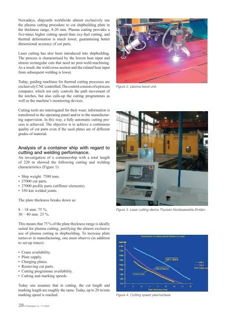
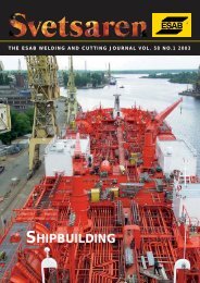
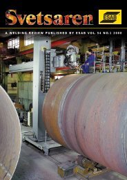
Nowadays, shipyards worldwide almost exclusively usethe plasma cutting procedure to cut shipbuilding plate inthe thickness range, 8-20 mm. Plasma cutting provides afive-times higher cutting speed than oxy-fuel cutting, andthermal deformation is much lower, guaranteeing betterdimensional accuracy of cut parts.Laser cutting has also been introduced into shipbuilding.The process is characterised by the lowest heat input andalmost rectangular cuts that need no post-weld-machining.As a result, the weld cross-section and the related heat inputfrom subsequent welding is lower.Today, guiding machines for thermal cutting processes areexclusively CNC controlled. The control consists of a processcomputer, which not only controls the path movement ofthe torches, but also calls-up the cutting programmes aswell as the machine’s monitoring devices.Figure 2. plasma bevel unit.Cutting tools are interrogated for their wear; information istransferred to the operating panel and/or to the manufacturingsupervision. In this way, a fully automatic cutting processis achieved. The objective is to achieve a continuousquality of cut parts even if the used plates are of differentgrades of material.Analysis of a container ship with regard tocutting and welding performance.An investigation of a containership with a total lengthof 220 m showed the following cutting and weldingcharacteristics (Figure 1):• Ship weight: 7500 tons.• 27000 cut parts.• 27000 profile parts (stiffener elements).• 350 km welded joints.The plate thickness breaks down as:8 – 18 mm: 75 %.30 – 40 mm: 25 %.Figure 3. Laser cutting device Thyssen Nordseewerke Emden.This means that 75 % of the plate thickness range is ideallysuited for plasma cutting, justifying the almost exclusiveuse of plasma cutting in shipbuilding. To increase plateturnover in manufacturing, one must observe (in additionto set-up times):Comparison of cutting speeds Plasma vs. Laser.• Crane availability.• Plate supply.• Charging plates.• Removing cut parts.• Cutting programme availability.• Cutting and marking speeds.Today one assumes that in cutting, the cut length andmarking length are roughly the same. Today, up to 20 m/minmarking speed is reached.Plate thickness (mm)Figure 4. Cutting speed plasma/laser.28 • Svetsaren no. 1 • 2005
Status of plasma cutting.In the quest for increased speeds in plasma cutting, plasmacutting with oxygen has consistently been further developed,because it guarantees the best results with regard to thequality of the bevel and the absence of slag. Currentsas high as 400A are now achieved which results in aconsiderable increase in cutting speed.However, with a higher current at the cutting nozzle, heatinput also increases, resulting in a more oblique cuttingedge. A possible remedy is to use a torch with bevel units,which position the torches at a slight incline (Figure 2).Naturally, cuts for weld edge preparation are carried outwith these machines; V and Y bevels with plasma torches,additionally K bevels using oxy-fuel torches.In plasma cutting, the consumption of wear parts(electrodes and tubes) is a cost factor which should not beunderestimated. Nowadays considerable life cycles havebeen achieved by consistent research and development.For example, the life cycle with oxygen cutting used tobe considerably shorter than with nitrogen cutting, at theinitial development stage. New developments, eg, a silvercoating on the hafnium electrodes, have considerablyincreased the life cycle of wear parts. Modern electronicshave also brought about considerable progress, ie, acontrolled increase and decrease of welding current at thestart and the end of the cutting sequence, respectively.Today, the life cycle of modern electrodes can exceed4 hours arc time.It is well known that plasma cutting generates airborneparticles, such as dust, IR and UV light, as well as highnoise levels. For this reason, in Europe, it was mostlyperformed under water. Water muffles the noise, bindsdust, and protects sufficiently from radiation. There aredisadvantages, however. Filling the water tables takestime, in comparison with dry tables. In addition, wetplates cannot be welded without loss of quality. Rust mayoccur on the bevel edge faces, and cutting particles mustbe cleaned from cut parts after water drainage. This iscarried out with high pressure water pumps, installed onthe cutting machine.There is a tendency, in Europe, for users to return to drycutting, as this technique offers considerable advantagesfor productivity, cut quality, charging – discharging.However, noise level is a major problem. Noise protectioncabins are provided for operating personnel and,sometimes, machines are encapsulated (modern cuttingmachines can operate fully automatically).Status of laser cuttingAs mentioned above, laser systems have been introducedinto shipbuilding, in shipbuilding nations such as theUSA, Korea, Italy, and Germany (Figure 3). However,the cutting speed is still lower and investment costs areconsiderably higher than those of a comparable plasmaFigure 5. Ink jet marking.Figure 6. Operator calling system.systems. On the other hand, wear costs are clearly lower;a precise cost comparison evaluation is not yet available,although in progress (Figure 4).Some arguments in favour of using a laser should not beunderestimated:• Cut faces can be used without further post-machining.• Noise level of a laser cutting machine remains insidepermissible limits.• Dry cut.• A laser system can be operated without personnel, aswear part consumption is very low (approx. 40 hourswithout operator activities).• Based on laser power of 5 or 6 kW (currently usedfor cutting), cutting speeds can be achieved which areregarded as acceptable.• Due to horizontal cutting edges, plates on both sides ofthe cut can be used immediately, reducing the cuttinglength and partly balancing the lower cutting speedcompared with plasma cutting.Svetsaren no. 1 • 2005 • 29