Aerodynamic Analyses of Horizontal Axis Wind Turbine ... - IOSRJEN
Aerodynamic Analyses of Horizontal Axis Wind Turbine ... - IOSRJEN
Aerodynamic Analyses of Horizontal Axis Wind Turbine ... - IOSRJEN

You also want an ePaper? Increase the reach of your titles
YUMPU automatically turns print PDFs into web optimized ePapers that Google loves.
ARVIND SINGH RATHORE, SIRAJ AHMED / IOSR Journal <strong>of</strong> Engineering (<strong>IOSRJEN</strong>)<br />
www.iosrjen.org ISSN : 2250-3021<br />
Vol. 2 Issue 1, Jan.2012, pp. 118-123<br />
<strong>Aerodynamic</strong> <strong>Analyses</strong> <strong>of</strong> <strong>Horizontal</strong> <strong>Axis</strong> <strong>Wind</strong> <strong>Turbine</strong> By Different Blade<br />
Airfoil Using Computer Program<br />
ARVIND SINGH RATHORE 1 , SIRAJ AHMED 2<br />
1 (Department <strong>of</strong> Mechanical Engineering Maulana Azad National Institute <strong>of</strong> Technology, Bhopal)<br />
2 (Department <strong>of</strong> Mechanical Engineering Maulana Azad National Institute <strong>of</strong> Technology, Bhopal)<br />
ABSTRACT :<br />
An aerodynamic analysis tool for analysis <strong>of</strong> horizontal axis<br />
wind turbine blades is developed by using both Blade Element<br />
Momentum (BEM) Theory and Computer Program. The<br />
method is used to optimize blade geometry to give the<br />
maximum power for a given wind speed, a constant<br />
rotational speed, a number <strong>of</strong> blades and a blade radius. The<br />
airfoil pr<strong>of</strong>iles and their aerodynamic data are taken from an<br />
existing airfoil database for which experimental lift and drag<br />
coefficient data are available. The goal <strong>of</strong> this study was to<br />
analyze the effects <strong>of</strong> different airfoil pr<strong>of</strong>iles blade on the<br />
overall wind turbine performance.<br />
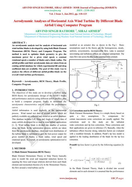
modeled as an actuator disc as shown in the Fig.1. Basic<br />
assumptions used in the theory are the homogeneous, steady,<br />
uniform, axisymmetric, incompressible flow, wake is assumed<br />
non-rotating and turbulence effects are assumed unimportant. The<br />
mass flow rate across the disc is also assumed to be constant.<br />
Keywords – <strong>Aerodynamic</strong>s, BEM Theory, Blade Pr<strong>of</strong>ile,<br />
Computer Program<br />
1. INTRODUCTION<br />
The objectives <strong>of</strong> this study are to develop a method using<br />
BEM theory for aerodynamic design <strong>of</strong> the HAWT blades<br />
and performance analysis using different airfoil pr<strong>of</strong>iles, also<br />
to build a computer program, finally to determine the<br />
aerodynamic characteristics and to create the performance<br />
curves.<br />
Airfoil information is used explicitly in the optimization<br />
process. <strong>Wind</strong> tunnel test data <strong>of</strong> several airfoils which are<br />
publicly available are collected and stored as an airfoil database.<br />
This database includes Lift, Drag and Angle <strong>of</strong> Attack data <strong>of</strong><br />
many airfoils developed for or used in wind turbine applications<br />
[1, 2]. <strong>Wind</strong> turbine blade is divided into number <strong>of</strong> sections<br />
along the blade. In the optimization process, airfoils are taken<br />
from the aerodynamic database, chord and twist distributions <strong>of</strong><br />
the turbine blade is optimized to give the best power output for<br />
given number <strong>of</strong> blades, a blade radius, wind speed and<br />
rotational speed. As a result, an aerodynamic optimization tool is<br />
developed.<br />
2. METHOD<br />
2.1 Blade Element Momentum (BEM) Theory:<br />
Blade Element Momentum Theory or Strip Theory basically<br />
aims to model the axial and tangential induction factors by<br />
equating the force and torque relations derived from each blade<br />
element and momentum theories [3]. In the Momentum Theory,<br />
the flow around a wind turbine can be<br />
Fig.-1<br />
2.2 Corrections used in BEM Theory:<br />
Blade Element Momentum Theory is a simple theory based on<br />
quite a few assumptions. To compensate for<br />
certain inaccuracies some corrections are usually applied. The<br />
corrections used in this study are the turbulent<br />
wake corrections and tip loss corrections. These corrections and<br />
their applications are given in reference [7]. Basically, when the<br />
turbulence effects become strong, induction factors are evaluated<br />
with a modified formula. In addition, Prantl’s tip loss model is<br />
applied to the loading distribution <strong>of</strong> the blade for the tip loss<br />
correction.<br />
Prandtl tip-loss factor is given by the following equation [4,<br />
5]<br />
In the Blade Element Theory, blade is divided into several<br />
elements and in each element it is assumed that the performance<br />
(1)<br />
www.iosrjen.org<br />
118 | P a g e
ARVIND SINGH RATHORE, SIRAJ AHMED / IOSR Journal <strong>of</strong> Engineering (<strong>IOSRJEN</strong>)<br />
www.iosrjen.org ISSN : 2250-3021<br />
Vol. 2 Issue 1, Jan.2012, pp. 118-123<br />
<strong>of</strong> the overall blade can be derived from the 2D airfoil which<br />
is used at that section by integrating it throughout the blade.<br />
Using the induction factor definitions, conservation <strong>of</strong> linear<br />
momentum and conservation <strong>of</strong> angular momentum equations<br />
are derived from blade element and momentum theories<br />
separately. The detailed derivations and explanations may be<br />
found in [4, 6]. Hence, in the Blade Element Momentum (BEM)<br />
Theory, a, a ′ and σ are given by:<br />
σ = B c/2πr (2)<br />
(3)<br />
(11)<br />
2.3 Airfoil Database:<br />
The airfoil pr<strong>of</strong>iles are obtained from an airfoil database. The<br />
database contains airfoils that are designed or used for wind<br />
turbine applications. The lift and drag coefficients <strong>of</strong> the airfoils,<br />
that are based on wind tunnel test, are listed for various angles <strong>of</strong><br />
attack and Reynolds numbers. The details <strong>of</strong> the database and the<br />
airfoil sections employed are given in reference [7].<br />
To find out the maximum power coefficient for a selected<br />
airfoil type, dividing the blade length into N elements, the<br />
local tip speed ratio for each blade element can then be<br />
calculated with the use <strong>of</strong> following equation [5]:<br />
Local Tip Speed Ratio<br />
Λ r,i = λ (r i /R) (5)<br />
Optimum Relative wind for each blade element<br />
(4)<br />
(6)<br />
Tip- loss factor for each blade element<br />
(7)<br />
(8)<br />
Fig.-2<br />
Twist distribution:<br />
Chord length distribution:<br />
Power coefficient<br />
(9)<br />
(10)<br />
2.4 Computer Program:<br />
Applying the design procedure explained a computer<br />
program is written in C-Sharpe Language using .NET<br />
Framework 4 to estimate the aerodynamic performance <strong>of</strong><br />
the various airfoil pr<strong>of</strong>iles. A detailed flow chart <strong>of</strong> the<br />
program is given in Fig.-3.<br />
The program take airfoil data, wind speed, radius <strong>of</strong> rotor, no<br />
<strong>of</strong> blades, density <strong>of</strong> air as input, no <strong>of</strong> blade elements and<br />
cut-out wind velocity as input. After calculation<br />
aerodynamic characteristic <strong>of</strong> different airfoil blades are<br />
plotted as output. In the blade design from root, tip and<br />
middle section taking the same airfoil. For comparing<br />
characteristic <strong>of</strong> airfoils, blade length taken as 21m and hub<br />
diameter 45m.<br />
www.iosrjen.org<br />
119 | P a g e
ARVIND SINGH RATHORE, SIRAJ AHMED / IOSR Journal <strong>of</strong> Engineering (<strong>IOSRJEN</strong>)<br />
www.iosrjen.org ISSN : 2250-3021<br />
Vol. 2 Issue 1, Jan.2012, pp. 118-123<br />
Fig.-3<br />
www.iosrjen.org<br />
120 | P a g e
ARVIND SINGH RATHORE, SIRAJ AHMED / IOSR Journal <strong>of</strong> Engineering (<strong>IOSRJEN</strong>)<br />
www.iosrjen.org ISSN : 2250-3021<br />
Vol. 2 Issue 1, Jan.2012, pp. 118-123<br />
3. RESULTS:<br />
3.1 Variation <strong>of</strong> power coefficient with Tip speed ratio<br />
3.3 Variation <strong>of</strong> twist with radial location.<br />
Fig.-4<br />
Power coefficient is increases as tip speed ratio increases but<br />
after certain limit it decreases for all the airfoil. Tip speed<br />
ratio at which power coefficient is maximum is called design<br />
tip speed ratio.<br />
3.2 variation <strong>of</strong> chord distribution with radial location<br />
Fig.-6<br />
Twisting angle is also decreases from root to tip and it is<br />
negative near the tip-section.<br />
3.4 Variation <strong>of</strong> modified chord distribution with radial<br />
location.<br />
Fig.-5<br />
Chord is maximum at root section and is minimum at tipsection.<br />
We can notice that the decreasing <strong>of</strong> chord length is<br />
not linear with the increasing <strong>of</strong> the radius.<br />
Fig-7<br />
Chord is modified for improving the aerodynamic property<br />
<strong>of</strong> blade and makes the chord distribution linear.<br />
www.iosrjen.org<br />
121 | P a g e
ARVIND SINGH RATHORE, SIRAJ AHMED / IOSR Journal <strong>of</strong> Engineering (<strong>IOSRJEN</strong>)<br />
www.iosrjen.org ISSN : 2250-3021<br />
Vol. 2 Issue 1, Jan.2012, pp. 118-123<br />
3.5. Variation <strong>of</strong> modified twist with radial location<br />
Fig.-10<br />
Fig.-8<br />
This modification has been performed such that twist<br />
distribution <strong>of</strong> the modified blade has been linearized. Also<br />
at some distance from blade root the twist becomes negative<br />
which generally causes the blade elements from this distance<br />
to blade tip to be stalled. To prevent these blade elements<br />
from being in stall region, their twist values are set to zero.<br />
3.8 View <strong>of</strong> blade airfoil from root to tip<br />
3.6. Variation <strong>of</strong> Power generated with wind velocity<br />
Fig.-11<br />
Fig.-9<br />
Power increases with wind speed, it is maximum at nominal<br />
wind velocity 14 m/sec and maximum power generated by<br />
NACA-2415 airfoil.<br />
Fig.-12<br />
3.7 Variation <strong>of</strong> power coefficient with no <strong>of</strong> blades<br />
www.iosrjen.org<br />
122 | P a g e
ARVIND SINGH RATHORE, SIRAJ AHMED / IOSR Journal <strong>of</strong> Engineering (<strong>IOSRJEN</strong>)<br />
www.iosrjen.org ISSN : 2250-3021<br />
Vol. 2 Issue 1, Jan.2012, pp. 118-123<br />
Fig.-13<br />
4. CONCLUSION<br />
In this paper a computer program is used for analysis <strong>of</strong><br />
aerodynamics <strong>of</strong> different airfoil. We take the 11 airfoils data<br />
for 21m length <strong>of</strong> blade out <strong>of</strong> which NACA-2415 airfoil has<br />
generated maximum power at nominal wind velocity. This<br />
program can be used for any number <strong>of</strong> airfoils.<br />
References:<br />
[1] Michael S. Selig and Bryan D. McGranahan ”<br />
<strong>Wind</strong> Tunnel <strong>Aerodynamic</strong> Tests <strong>of</strong> Six Airfoils for<br />
Use on Small <strong>Wind</strong> <strong>Turbine</strong>s” January 31, 2003<br />
[2] Eke G.B., Onyewudiala J.I. “Optimization <strong>of</strong><br />
<strong>Wind</strong> <strong>Turbine</strong> Blades Using Genetic<br />
Algorithm”Global Journal <strong>of</strong> Researches in<br />
Engineering 22 Vol. 7 (Ver 1.0), December 2010.<br />
[3] Ali Vardar, Ilknur Alibas, “Research on wind<br />
turbine rotor models using NACA pr<strong>of</strong>iles”;<br />
Renewable Energy 33 (2008) 1721–1732<br />
[4] Manwell, J. F., McGowan, J. G., Rogers, A. L.,<br />
“<strong>Wind</strong> Energy Explained; Theory, Design and<br />
Application”, John Wiley & Sons Ltd, 2002<br />
[5] Spera, D. A., “<strong>Wind</strong> <strong>Turbine</strong> Technology”, ASME<br />
Press, 1998<br />
[6] J. F. Manwell, J. G. McGowan, A. L. Rogers<br />
Wing Energy, Theory, Design and Applications,<br />
Contract NAS2-11665, Muadyne Report 83-2-3, John<br />
Wiley and Sons, 2006.<br />
[7] Ceyhan O., <strong>Aerodynamic</strong> Design and Optimization<br />
<strong>of</strong> <strong>Horizontal</strong> <strong>Axis</strong> <strong>Wind</strong> turbines by Using BEM<br />
Theory and Genetic Algorithm, Master Thesis,<br />
Aerospace Engineering Department, METU, Ankara,<br />
2008.<br />
Nomenclature:<br />
C p : Power coefficient <strong>of</strong> wind turbine rotor<br />
P: Power output from wind turbine rotor<br />
m: Air mass flow rate through rotor plane<br />
U: Free stream velocity <strong>of</strong> wind<br />
U re1 : Relative wind velocity<br />
U R : Uniform wind velocity at rotor plane<br />
A: Area <strong>of</strong> wind turbine rotor<br />
R: Radius <strong>of</strong> wind turbine rotor<br />
r: Radial coordinates at rotor plane<br />
r i : Blade radius for the i th blade element<br />
T: rotor thrust<br />
Q: rotor torque<br />
C D : Drag coefficient <strong>of</strong> an airfoil<br />
C L : Lift coefficient <strong>of</strong> an airfoil<br />
F: Tip-loss factor<br />
F i : Tip-loss factor for the i th blade element<br />
N: Number <strong>of</strong> blade elements<br />
B: Number <strong>of</strong> blades <strong>of</strong> a rotor<br />
a: Axial induction factor at rotor plane<br />
a' : Angular induction factor<br />
λ: Tip-speed ratio <strong>of</strong> rotor<br />
λ d : Design Tip- Speed ratio <strong>of</strong> rotor<br />
λr: local Tip- Speed ratio <strong>of</strong> rotor<br />
λr,i: Local tip-speed ratio for the i th blade element<br />
C i :: Blade chord length for the i th blade element<br />
ρ: Air density<br />
Ω : Angular velocity <strong>of</strong> wind turbine rotor<br />
α : Angle <strong>of</strong> attack<br />
θ i : Pitch angle for the i th blade element<br />
φ opti: Optimum relative wind angle for the i th blade<br />
σ: Solidity ratio<br />
ν: Kinematic viscosity <strong>of</strong> air<br />
γ: Glide ratio<br />
Re: Reynolds number<br />
HAWT: <strong>Horizontal</strong>-axis wind turbine<br />
BEM: Blade element momentum<br />
element<br />
www.iosrjen.org<br />
123 | P a g e