Pneumatic Systems Chapter 7 Pneumatic and Hydraulic Systems
Pneumatic Systems Chapter 7 Pneumatic and Hydraulic Systems
Pneumatic Systems Chapter 7 Pneumatic and Hydraulic Systems

Create successful ePaper yourself
Turn your PDF publications into a flip-book with our unique Google optimized e-Paper software.
<strong>Chapter</strong> 7 <strong>Pneumatic</strong> <strong>and</strong> <strong>Hydraulic</strong> <strong>Systems</strong><br />
1<br />
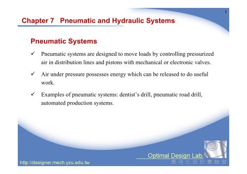
<strong>Pneumatic</strong> <strong>Systems</strong><br />
<br />
<br />
<br />
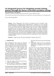
<strong>Pneumatic</strong> systems are designed to move loads by controlling pressurized<br />
air in distribution lines <strong>and</strong> pistons with mechanical or electronic valves.<br />
Air under pressure possesses energy which can be released to do useful<br />
work.<br />
Examples of pneumatic systems: dentist’s drill, pneumatic road drill,<br />
automated production systems.
Components of a <strong>Pneumatic</strong> System<br />
2<br />
compressor<br />
motor<br />
reservoir<br />
distribution<br />
lines<br />
air<br />
treatment<br />
cylinders <strong>and</strong> valves<br />
<br />
<br />
Compressor is the power source of a pneumatic system. It is usually driven by a<br />
motor or an internal combustion engine. The compressed air is first stored in a<br />
strong metal tank called reservoir.<br />
Before entering the cylinders <strong>and</strong> valves, the compressed air has to pass through<br />
the air treatment devices, including air filter to remove dust <strong>and</strong> moisture,<br />
pressure regulator to adjust pressure, <strong>and</strong> lubricator to spray lubrication oil.
Air Filter -- to remove dust <strong>and</strong> moisture<br />
3<br />
air<br />
filter<br />
condensed<br />
water<br />
water release<br />
valve
Pressure Regulator -- to adjust pressure<br />
adjust screw<br />
ventilation hole<br />
spring<br />
diaphragm<br />
4<br />
valve
Lubricator -- to spray lubrication oil<br />
5<br />
siphon<br />
tube<br />
lubrication oil
<strong>Pneumatic</strong> Actuator -- Cylinder<br />
6<br />
Cylinder is the actuator in the pneumatic system. When compressed air flows<br />
into a cylinder, energy stored in the air will release, transferring into kinetic<br />
energy to do work.<br />
compressed air<br />
exhaust
Example 1. Calculating the force produced by a cylinder<br />
7<br />
The input air pressure is 0.5 MPa, which means the air would exert a force of<br />
0.5N on each square millimeters. If the area of the piston is 300mm 2 , then the<br />
total force produced by the cylinder will be:<br />
force = pressure × piston area<br />
= 0.5 N/mm 2 × 300mm 2<br />
= 150 N<br />
2<br />
300 mm<br />
compressed 壓 縮 氣 air 體 0.5MPa
<strong>Pneumatic</strong> Motor – Piston Type <strong>and</strong> Vane Type<br />
8<br />
piston rod<br />
output shaft<br />
piston<br />
inlet<br />
outlet
Example 2. <strong>Pneumatic</strong> Drill<br />
9<br />
control lever<br />
air inlet<br />
air duct<br />
disk valve<br />
piston<br />
air flow<br />
air outlet<br />
anvil<br />
air flow<br />
spring<br />
blade<br />
(a)<br />
(b)
Pressure Control Valve – Relieve Valve<br />
10<br />
Relief valve, also known as safety valve,<br />
is used to maintain the desired pressure.<br />
adjust screw<br />
spring<br />
ball valve
Pressure Control Valve—Reduce Valve<br />
adjust screw<br />
11<br />
spring<br />
diaphragm<br />
減 壓 閥 表 示 符 號
Directional Control Valve – Two Port Valve (2/2)<br />
12<br />
IN<br />
IN<br />
OUT<br />
OUT<br />
Directional control valves are<br />
commonly described by an x/y<br />
designation, where x is the number of<br />
ports <strong>and</strong> y is the number of positions.<br />
2/2 valve: 2 ports, 2 positions.<br />
The two port valve is similar to the<br />
single pole single throw switch in<br />
electric circuits.
Directional Control Valve – Three Port Valve (3/2)<br />
13<br />
The three port valve is similar to the<br />
single pole double throw switch in<br />
electric circuits.<br />
3<br />
出 氣 口<br />
exhaust<br />
3<br />
2<br />
2<br />
氣 壓 源<br />
1<br />
air supply<br />
spring<br />
彈 簧<br />
1
Example 3. <strong>Pneumatic</strong> Punching Machine (I)<br />
14<br />
single 氣 壓 缸 acting cylinder<br />
方 three 向 控 port 制 閥 valve (3/2)<br />
沖 punching 壓 模 mold
Example 3. <strong>Pneumatic</strong> Punching Machine (II)<br />
15<br />
3<br />
1<br />
2<br />
3<br />
1<br />
2<br />
(a)<br />
(b)
Directional Control Valve – One Way Valve<br />
16<br />
<br />
The one way valve allows air flow from only one direction. It is similar to<br />
the diode in electric circuits.<br />
ball 球 valve 閥<br />
止 回 閥 表 示 符 號
Directional Control Valve – Shuttle Valve<br />
17<br />
<br />
<br />
A shuttle valve has three ports <strong>and</strong> contains a small rubber piston which is<br />
free to move between port 1A <strong>and</strong> 1B within the valve.<br />
If air enters the valve through port 1 A or 1B, the piston is pushed to the<br />
other side <strong>and</strong> air can only escape through port 2.<br />
2<br />
閥 valve<br />
2<br />
1A<br />
1B<br />
1A<br />
1B<br />
2<br />
1<br />
1<br />
梭 動 閥 氣 壓 表 示 符 號
Example 4: Dual Control <strong>Pneumatic</strong> Punching Machine<br />
18<br />
A<br />
D<br />
a<br />
3<br />
1<br />
B<br />
2<br />
C<br />
b<br />
3<br />
1<br />
2
Flow Control Valve – the Flow Regulator<br />
Air can pass through the<br />
regulator in either direction.<br />
If air enters from left, the ball<br />
valve is pushed open <strong>and</strong> air<br />
can flow through the valve<br />
unrestricted.<br />
If air enters from right, the<br />
ball valve is closed so that air<br />
can only pass through the<br />
regulator.<br />
The flow of air can be<br />
controlled by turning a finger<br />
screw.<br />
IN<br />
ball 球 valve 閥<br />
spring 彈 簧<br />
finger 調 整 screw 螺 栓<br />
needle 針 形 閥 valve<br />
OUT<br />
19
Control of Double Acting Cylinders (I)<br />
20<br />
five 五 口 二 port 位 置 valve 方 向 閥 (5/2)<br />
流 量 控 制 閥<br />
flow control valve
Control of Double Acting Cylinders (II)<br />
<br />
<br />
Unlike a single acting cylinder, a double acting cylinder does not contain a<br />
return spring. Movements in both directions are powered by compressed air.<br />
The flow control valve makes the downward movement of piston 2 slower<br />
than that of piston 1. However, both pistons move upward at the same speed.<br />
21<br />
1 2<br />
3<br />
1<br />
5
Air Operated Valves<br />
22<br />
<br />
<br />
<br />
In the valves described so far, the spool which controls the flow of air is<br />
moved mechanically, by a button or lever.<br />
In order to be automated, direction control valves in the pneumatic systems<br />
have to be controlled by air pressure or electrical signals.<br />
In air operated valves, the spool is moved by air pressure.<br />
4<br />
2<br />
2<br />
5 1<br />
3<br />
3 1
Example 5: Application of Air Operated Valves<br />
23<br />
4 2<br />
14 12<br />
5<br />
1<br />
3<br />
安 safe 全 區 region<br />
域<br />
2<br />
1<br />
3<br />
3<br />
1 2
<strong>Pneumatic</strong> Solenoid Valves<br />
24<br />
<br />
The spool position is moved by an electrical solenoid, <strong>and</strong> can controlled<br />
electronically.<br />
+V +V<br />
electrical solenoid<br />
電 磁 線 圈<br />
spool 閥<br />
(a)<br />
(b)
<strong>Hydraulic</strong>s<br />
25<br />
<br />
The working fluid in a hydraulic system is incompressible. Thus a hydraulic<br />
system can move large loads.<br />
50N<br />
400N<br />
Pascal’s Law<br />
100mm 2<br />
800mm 2<br />
A<br />
B
<strong>Hydraulic</strong> <strong>Systems</strong><br />
26<br />
<br />
<strong>Pneumatic</strong> systems are open systems, always processing new air, <strong>and</strong> air is<br />
simply exhausted to the atmosphere. <strong>Hydraulic</strong> systems are closed systems,<br />
always recirculating the same oil.<br />
cylinder<br />
oil pump<br />
motor<br />
hydraulic<br />
valves<br />
oil<br />
reservoir
Example 6. <strong>Hydraulic</strong> Jack<br />
27<br />
Only a small force is required<br />
by the operator to raise the<br />
heavy load. The large piston<br />
can be stopped at any point<br />
because the oil cannot be<br />
compressed.<br />
h<strong>and</strong>le<br />
small<br />
piston<br />
large<br />
piston<br />
one-way<br />
valve<br />
valve<br />
release screw
<strong>Hydraulic</strong> Actuators<br />
28<br />
<br />
<br />
In a hydraulic system, the actuators transferring hydraulic energy into<br />
mechanical motion are hydraulic cylinders <strong>and</strong> hydraulic motors.<br />
There are 3 types of hydraulic motors : gear pump, vane pump <strong>and</strong> axial<br />
piston pump.<br />
low pressure oil<br />
high pressure oil
Example 7. <strong>Hydraulic</strong> Brakes<br />
29<br />
brake fluid<br />
disc<br />
master cylinder<br />
brake pedal<br />
brake<br />
pads<br />
brake fluid<br />
piston<br />
disc<br />
caliper<br />
wheel<br />
cylinder
Example 8. <strong>Hydraulic</strong> Control loop<br />
30<br />
filter<br />
control<br />
valve<br />
cylinder<br />
oil<br />
reservoir<br />
relief valve<br />
pump
Comparison between <strong>Pneumatic</strong> <strong>and</strong> <strong>Hydraulic</strong> <strong>Systems</strong><br />
31<br />
Advantages<br />
<strong>Pneumatic</strong> System<br />
Air is easily available<br />
Fast response<br />
Air is non-flammable<br />
Continuous variable transmission<br />
<strong>Hydraulic</strong> System<br />
High output force<br />
Accurate hydraulic pressure<br />
No corrosion<br />
Continuous variable<br />
transmission
Comparison between <strong>Pneumatic</strong> <strong>and</strong> <strong>Hydraulic</strong> <strong>Systems</strong><br />
32<br />
Disadvantages<br />
<strong>Pneumatic</strong> System<br />
• Output force is limited<br />
• Compressibility of air<br />
• Corrosion may occur<br />
• Pipe length is limited<br />
<strong>Hydraulic</strong> System<br />
• Fluid might leak out<br />
• Fluid will degrade due to heat<br />
• Fluid flow speed is limited<br />
• Pipes are complicated<br />
• Working fluid is often flammable.<br />
Electrical Linear Actuator