ASM Vehicle Dynamics Simulation Package - Humusoft
ASM Vehicle Dynamics Simulation Package - Humusoft
ASM Vehicle Dynamics Simulation Package - Humusoft

Create successful ePaper yourself
Turn your PDF publications into a flip-book with our unique Google optimized e-Paper software.
<strong>ASM</strong> <strong>Vehicle</strong> <strong>Dynamics</strong><br />
<strong>Simulation</strong> <strong>Package</strong><br />
• dSPACE Automotive <strong>Simulation</strong> Models – <strong>ASM</strong><br />
• <strong>Vehicle</strong> <strong>Dynamics</strong> Model and ModelDesk<br />
• NEW: Operator Version optimized for offline simulation
Automotive <strong>Simulation</strong> Model<br />
<strong>ASM</strong> <strong>Vehicle</strong> <strong>Dynamics</strong> <strong>Simulation</strong><br />
<strong>Package</strong><br />
Real-Time <strong>Vehicle</strong> <strong>Dynamics</strong> Model<br />
Key Features<br />
• Open MATLAB ® /Simulink ® model<br />
• Real-time simulation and offline<br />
simulation<br />
• Intuitive graphical parameterization,<br />
road and maneuver creation in<br />
ModelDesk<br />
• NEW: Custom Component<br />
Parameterization<br />
• NEW: Operator version optimized for<br />
offline simulation<br />
• Tool automation for ModelDesk<br />
• 3-D animation<br />
Description<br />
Application Areas<br />
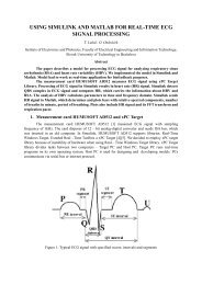
The <strong>ASM</strong> <strong>Vehicle</strong> <strong>Dynamics</strong> <strong>Simulation</strong> <strong>Package</strong><br />
is an open Simulink model for the real-time<br />
simulation of vehicle dynamics behaviors within<br />
an environment. The model is typically used on<br />
a dSPACE Simulator for hardware-in-the-loop<br />
testing of electronic control units (ECUs) or during<br />
the design phase of controller algorithms<br />
for early validation by offline simulation. It is<br />
a complete and independent model that supports<br />
all the relevant phases of the model-based<br />
development process.<br />
Key Benefits<br />
All the Simulink blocks in the model are visible,<br />
so it is easy to add or replace components with<br />
custom models to adapt the vehicle’s properties<br />
perfectly to individual projects. <strong>ASM</strong>’s standardized<br />
interfaces allow the vehicle dynamics model<br />
to be easily expanded to meet specific requirements<br />
or even create a virtual vehicle. Roads and<br />
driving maneuvers can be easily and intuitively<br />
created using graphical tools with preview and<br />
clear visualization. All parameters can be altered<br />
during run time.<br />
<strong>Vehicle</strong> Characteristics<br />
The actual physical vehicle characteristics are represented<br />
by a multibody system with 24 degrees<br />
of freedom. It consists of a drivetrain with elastic<br />
shafts, a table-based engine, two semi-empirical<br />
tire models, a nonlinear or table-based vehicle<br />
multibody system with geometrical suspension<br />
kinematics and aerodynamics, and a steering<br />
model. An environment with a road, maneuvers,<br />
and an open- and closed-loop driver is included<br />
as well. All parameters can be altered during<br />
run time. The included brake hydraulics model<br />
consists of a dual-circuit hydraulics system.<br />
Offline and Online <strong>Simulation</strong><br />
The <strong>ASM</strong> <strong>Vehicle</strong> <strong>Dynamics</strong> <strong>Simulation</strong> <strong>Package</strong><br />
can be used in combination with real controllers<br />
in a hardware-in-the-loop environment (HIL or<br />
online mode), or for simulating a vehicle in combination<br />
with software controller algorithms (PC<br />
or offline mode). The model supports real-time<br />
code generation via The MathWork’s Real-Time<br />
Workshop ® and dSPACE’s RTI for online simulation<br />
on a dSPACE real-time system.<br />
2<br />
2008
<strong>Vehicle</strong> <strong>Dynamics</strong> <strong>Simulation</strong> <strong>Package</strong><br />
Main Features and Benefits<br />
Feature Description Benefit<br />
Open Simulink model • All model blocks visible • Custom models can easily be added or used to<br />
replace model components (p. 13)<br />
ModelDesk<br />
Online simulation<br />
Offline simulation<br />
Online tunable<br />
parameters<br />
<strong>ASM</strong>SignalBus<br />
• Graphical user interface with parameter<br />
management<br />
• Real-time simulation on real-time hardware, e.g.,<br />
DS1006<br />
• <strong>Simulation</strong>s as early as the controller algorithm<br />
design phase<br />
• Direct parameter access during real-time simulations<br />
• <strong>Simulation</strong> signals part of a structured Simulink<br />
signal bus<br />
• Easy parameter handling, maneuver planning, and<br />
road construction (p. 14)<br />
• Hardware-in-the-loop simulations with productionlevel<br />
ECUs<br />
• Controller validation in early development stages<br />
• Online parameter optimizations and behavior<br />
studies (p. 12)<br />
• Standardized and fast access to model variables<br />
(p. 12)<br />
Model interoperability • <strong>ASM</strong> models easy to combine to create a virtual vehicle • An entire virtual vehicle can be simulated (p. 13)<br />
Order Information<br />
Classification Type Order Number<br />
Base model <strong>ASM</strong> <strong>Vehicle</strong> <strong>Dynamics</strong> <strong>Simulation</strong> <strong>Package</strong> • <strong>ASM</strong>_P_VD<br />
Extension models <strong>ASM</strong> Gasoline Engine <strong>Simulation</strong> <strong>Package</strong> • <strong>ASM</strong>_P_GE<br />
<strong>ASM</strong> Gasoline Engine Basic <strong>Simulation</strong> <strong>Package</strong><br />
<strong>ASM</strong> Diesel Engine <strong>Simulation</strong> <strong>Package</strong><br />
<strong>ASM</strong> Brake Hydraulics Model<br />
<strong>ASM</strong> Traffic<br />
Relevant Hardware and Software<br />
<strong>ASM</strong> Electric Components<br />
• <strong>ASM</strong>_P_GEB<br />
• <strong>ASM</strong>_P_DE<br />
• <strong>ASM</strong>_L_BH<br />
• please inquire<br />
• please inquire<br />
Hardware<br />
Required Minimum system • Pentium 4 processor, 1.4 GHz or higher 1)<br />
• Memory ≥ 1 GB RAM 1)<br />
• High-performance graphics accelerator card<br />
(OpenGL-compliant), 32 MB RAM 2)<br />
Recommended system<br />
• Workstation with Pentium 4 processor ≥ 3.2 GHz<br />
• Memory 2 GB RAM<br />
• High-performance, dual-head graphics accelerator<br />
card (OpenGL-compliant), ≥ 128 MB RAM 2)<br />
dSPACE Simulator, equipped with<br />
• DS1005 or DS1006<br />
Software for Online <strong>Simulation</strong><br />
Required Integrated development environment • MATLAB ® /Simulink ® from The MathWorks<br />
• Real-Time Workshop ®<br />
Operating system<br />
• www.dspace.com/goto?os_compatibility<br />
dSPACE implementation software<br />
• Real-Time Interface (RTI)<br />
dSPACE experiment software<br />
• ControlDesk<br />
Included dSPACE experiment software • ModelDesk<br />
dSPACE experiment software<br />
• MotionDesk<br />
Optional Other simulation models from dSPACE • <strong>ASM</strong> <strong>Package</strong>s<br />
Software for Offline <strong>Simulation</strong><br />
Required Integrated development environment • MATLAB ® /Simulink ® from The MathWorks<br />
Operating system<br />
• www.dspace.com/goto?os_compatibility<br />
Included dSPACE experiment software • ModelDesk<br />
dSPACE experiment software<br />
• MotionDesk<br />
Optional Other simulation models from dSPACE • <strong>ASM</strong> <strong>Package</strong>s<br />
1)<br />
A standard Pentium 3 processor and 512 MB RAM are sufficient if MotionDesk is not used on the same PC.<br />
2)<br />
Graphics accelerator required for MotionDesk. A list of recommended graphics cards is available at www.dspace.de/goto?appnote<br />
3<br />
2008
Automotive <strong>Simulation</strong> Models<br />
<strong>ASM</strong> <strong>Vehicle</strong><br />
Feature Overview<br />
Features at a Glance<br />
• Multibody system<br />
• 24 degrees of freedom<br />
• Modular, library-based implementation<br />
• Environment model including road, driver,<br />
and maneuvers<br />
• Brake hydraulics module<br />
• Easily expandable to a comprehensive<br />
virtual vehicle with <strong>ASM</strong> engines<br />
• Custom models can be integrated and<br />
parameterized via graphical user interface<br />
• <strong>Vehicle</strong> parameters tunable online during<br />
run time (for example, via ControlDesk or<br />
ModelDesk)<br />
• Graphical user interface for<br />
parameterization (p. 14)<br />
• Fully integrated into dSPACE tool chain<br />
• Comprehensive documentation including<br />
formulas<br />
Model Components<br />
<br />
<br />
<br />
<br />
<br />
<br />
Engine Speed<br />
Engine Torque<br />
<br />
<br />
<br />
<br />
<br />
<br />
The vehicle dynamics model<br />
consists of subsystems for<br />
a vehicle body with its<br />
drivetrain, a complete<br />
environment, and a basic<br />
engine.<br />
The model can be extended<br />
by adding other model<br />
packages from dSPACE or<br />
custom models.<br />
<br />
<br />
<br />
<br />
<br />
4<br />
2008
<strong>Vehicle</strong> <strong>Dynamics</strong> <strong>Simulation</strong> <strong>Package</strong><br />
Engine Model<br />
The engine model includes a table-based engine<br />
and allows ECU interventions to reduce engine<br />
torque, for example, if requested by ASR or ESP<br />
systems. The engine can be switched on and<br />
off and hold a specific idle speed if necessary,<br />
for example, when declutched or thrown out<br />
of gear.<br />
Components and Characteristics<br />
• Table-based engine model<br />
• Several strategies (injection, throttle)<br />
for reducing and increasing torque as<br />
requested by the engine ECU<br />
• Starter to accelerate the engine to idle<br />
speed<br />
The table-based engine model can be replaced by<br />
a full-featured diesel or gasoline engine model.<br />
• Order information (p. 3)<br />
Engine and Drivetrain<br />
Engine torque is derived from the engine map.<br />
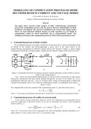
Drivetrain Model<br />
The drivetrain model has manual and automatic<br />
transmission, and front-, rear-, and all-wheeldrive.<br />
The shaft drives are modeled as elastic<br />
components.<br />
Components and Characteristics<br />
• Clutch with elasticity (torsion spring)<br />
• Elastic shafts included<br />
• Front-, rear-, and all-wheel drive including<br />
differentials<br />
• Manual and automatic transmission with<br />
torque converter<br />
• Model stabilized by semi-implicit Euler<br />
integration method<br />
• Drivetrain with 13 degrees of freedom<br />
(DoF)<br />
Overview of the drivetrain<br />
model configured with allwheel<br />
drive. Modes for rearand<br />
front-wheel drive are<br />
also available.<br />
5<br />
2008
Automotive <strong>Simulation</strong> Models<br />
<strong>Vehicle</strong> <strong>Dynamics</strong><br />
<strong>Vehicle</strong> Multibody System Model<br />
The system is modeled as a nonlinear vehicle<br />
multibody system with geometrical or tablebased<br />
suspension kinematics and table-based<br />
compliances. It supports the simulation of vertical,<br />
longitudinal, and lateral dynamics.<br />
Geometrical Suspension Models<br />
The kinematic behaviors of common suspension<br />
types are implemented as precise analytical equations<br />
which are solved during each simulation<br />
step. User-definable geometrical linkage points<br />
connect the suspension with the wheel carrier<br />
and the chassis.<br />
There is no preprocessing required, so the linkage<br />
points can be changed during offline and<br />
online simulation.<br />
The geometrical suspension models cover the<br />
whole range of input data, for example, wheel<br />
lift or steering rod displacement. To combine the<br />
kinematics with compliance effects, compliance<br />
look-up tables can be superimposed on the kinematics<br />
calculated in the geometrical suspension<br />
models.<br />
The <strong>ASM</strong> <strong>Vehicle</strong> <strong>Dynamics</strong> <strong>Simulation</strong> <strong>Package</strong> supports either table-based suspensions to<br />
be parameterized with measured suspension data or geometrical suspensions, for example<br />
McPherson strut, that can be parameterized graphically via user-definable linkage points (p. 17).<br />
Components and Characteristics<br />
• Multibody system (MBS) consisting of car<br />
body and four wheels<br />
• 11 degrees of freedom (DoF)<br />
• Geometrical description of suspen sions via<br />
user-definable linkage points<br />
• Suspension types: McPherson strut (front),<br />
semi-trailing arm (rear), rigid axle (rear)<br />
• Table-based compliances for suspensions<br />
• Suspension with nonlinear spring and<br />
damper characteristics<br />
• Aerodynamics forces and torques included<br />
• Brake model<br />
• Additional masses (fixed on vehicle body)<br />
• Rack and pinion steering system with<br />
included power steering<br />
• Two tire models: Magic Formula and TMEasy<br />
• 1st-order lateral, longitudinal, and vertical<br />
tire dynamics<br />
• Tires with combined lateral and<br />
longitudinal slip<br />
• Data import from suspension design tools<br />
available on request<br />
Item<br />
DoF<br />
Elastic powertrain 13<br />
Body 6<br />
Steering rod 1<br />
Wheels 4 1)<br />
1)<br />
One independent degree of freedom (DoF) per wheel for wheel<br />
vertical displacement. The wheel kinematics are included via the<br />
MBS algorithm.<br />
6<br />
2008
<strong>Vehicle</strong> <strong>Dynamics</strong> <strong>Simulation</strong> <strong>Package</strong><br />
<strong>Vehicle</strong> <strong>Dynamics</strong><br />
<strong>Vehicle</strong> dynamics model including aerodynamic forces.<br />
Steering Model<br />
The steering model simulates a rack-and-pinion<br />
steering system applied to the front wheels.<br />
Components and Characteristics<br />
• Power steering included<br />
• Tire forces and torques, and driving<br />
torque, included<br />
Rack-and-pinion steering system.<br />
Tire Model<br />
The vehicle model includes two tire models based<br />
on the published model descriptions Magic Formula<br />
and TMEasy, which are both fully implemented.<br />
Components and Characteristics<br />
• Magic Formula and TMEasy<br />
• Semiphysical approach<br />
• 1st-order lateral, longitudinal, and vertical<br />
dynamics<br />
• Standstill condition included<br />
• Dynamic tire radius<br />
• Camber angle influence<br />
• Combined lateral and longitudinal slip<br />
• Self-aligning and bore torques<br />
• Up to four tire characteristics for different<br />
road surface conditions, switchable online<br />
Lateral tire dynamics.<br />
7<br />
2008
Automotive <strong>Simulation</strong> Models<br />
Environment<br />
Road Model<br />
Roads are built in ModelDesk’s graphical Road<br />
Generator. A complete track is made up of several<br />
road segments, which can have different<br />
surfaces and profiles. A road segment surface<br />
consists of four longitudinal strips that can have<br />
individual properties.<br />
Components and Characteristics<br />
• Graphical road builder (p. 18)<br />
• Road consists of road segments<br />
• Different road segment types: straight,<br />
circle, clothoid, and spline<br />
• Longitudinal profile with slope and lateral<br />
inclination<br />
• Four longitudinal surface strips for defining<br />
different friction areas or additional road<br />
profiles (bumps, etc.).<br />
A road segment consists of four strips, and<br />
right and left margins, and can have a lateral<br />
slope.<br />
Driver Model<br />
The driver model controls the vehicle. Its main<br />
tasks are to drive the vehicle at a desired<br />
velocity and follow a given road. The vehicle is<br />
controlled via accelerator pedal, brake pedal,<br />
clutch pedal, gear lever, and steering wheel. It<br />
features foresight steering behavior to follow<br />
the road ahead.<br />
Components and Characteristics<br />
• Longitudinal controller for accelerator<br />
pedal and brake pedal, comprising<br />
feedforward and feedback control<br />
• Lateral controller for steering wheel, using<br />
preview information for road-following<br />
• Gear shifter for manual transmission,<br />
including startup<br />
• Reference velocity calculation for driving<br />
on arbitrary roads<br />
Overview driver model.<br />
8<br />
2008
<strong>Vehicle</strong> <strong>Dynamics</strong> <strong>Simulation</strong> <strong>Package</strong><br />
Maneuver Model<br />
Maneuvers define how a vehicle moves. Depending<br />
on the maneuver mode, they either provide<br />
stimulus signals directly to certain vehicle components<br />
like accelerator pedal, clutch pedal,<br />
brake pedal, steering wheel and gear lever, or<br />
give instructions to a driver model, which controls<br />
the vehicle.<br />
Components and Characteristics<br />
• Graphical maneuver editor (p. 19))<br />
• Maneuver creation via time and distance<br />
• Stimulus maneuvers according to<br />
measured data<br />
• Initialization control for road and vehicle<br />
model<br />
• NEW: Additional interfaces for traffic<br />
simulation (see <strong>ASM</strong> Traffic)<br />
Environment<br />
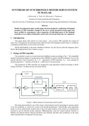
<strong>Simulation</strong> Results<br />
Validation results for different vehicles show that<br />
the simulation matches the measured vehicle<br />
dynamics data.<br />
For validation, maneuvers driven on a test track<br />
were also driven in ModelDesk, using the actual<br />
vehicle velocity and steering angles as inputs.<br />
Model Validation<br />
<br />
<br />
<br />
<br />
<br />
<br />
<br />
<br />
<br />
<br />
<br />
<br />
<br />
<br />
<br />
<br />
<br />
<br />
<br />
<br />
<br />
<br />
<br />
<br />
<br />
<br />
<br />
<br />
<br />
<br />
Comparison of<br />
a sine steering<br />
maneuver for a<br />
fully loaded van<br />
(weight 3.5 t).<br />
<br />
<br />
<br />
<br />
<br />
<br />
<br />
<br />
<br />
<br />
<br />
<br />
<br />
<br />
<br />
<br />
<br />
<br />
<br />
<br />
<br />
<br />
<br />
<br />
<br />
<br />
<br />
<br />
<br />
<br />
Comparison of<br />
a step steering<br />
maneuver for a<br />
passenger car at<br />
100 km/h and a<br />
steering angle<br />
of 38°.<br />
9<br />
2008
Automotive <strong>Simulation</strong> Models<br />
Virtual Test Bench<br />
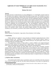
<strong>Vehicle</strong> Characteristics <strong>Simulation</strong><br />
<strong>ASM</strong> - <strong>Vehicle</strong> <strong>Dynamics</strong> is ideal to investigate vehicle<br />
characteristics on a virtual test bench or on<br />
the simulated road. Self steering behavior, pitch,<br />
roll axis and axle kinematics can be easily derived<br />
from simulations and visualized in MotionDesk.<br />
Results of analyzing vehicle self-steering behavior:<br />
Components and Characteristics<br />
• Virtual test bench simulation<br />
• Axle kinematics and compliance<br />
• Self steering behavior<br />
• Pitch and roll axis<br />
4<br />
Self Steering Behaviour<br />
3.5<br />
¯δt [ ] (Mean Angle T oe)<br />
°<br />
3<br />
2.5<br />
2<br />
1.5<br />
SSG= 0.19· s 2 ·<br />
°<br />
m<br />
δ A = l R · 180 °<br />
π<br />
SSG=0<br />
1<br />
0 1 2 3 4 5 6 7<br />
m<br />
a y s 2<br />
[ ]<br />
<strong>Simulation</strong> results of vehicle<br />
self-steering behavior.<br />
10<br />
Yaw Amplification<br />
9<br />
8<br />
7<br />
6<br />
˙Ψ<br />
δA<br />
= vx<br />
δA · R<br />
= vx<br />
l SSG= 0<br />
[ s ]<br />
˙Ψ¯δt<br />
1<br />
5<br />
4<br />
3<br />
2<br />
1<br />
v ch = 19.4<br />
0<br />
0 5 10 15 20 25 30<br />
m v x [ s ]<br />
Yaw amplification results from<br />
self-steering analysis simulation.<br />
4<br />
3<br />
α<br />
β<br />
Roll and Sideslip Angle<br />
2<br />
α and β [ ]<br />
°<br />
1<br />
0<br />
−1<br />
−2<br />
Roll and sideslip angle during<br />
self-steering investigations.<br />
−3<br />
0 1 2 3 4 5 6 7<br />
m a y s 2<br />
[ ]<br />
10<br />
2008
<strong>Vehicle</strong> <strong>Dynamics</strong> <strong>Simulation</strong> <strong>Package</strong><br />
Virtual Test Bench<br />
Visualization of the test bench during pitch and roll axis or axle kinematics investigations.<br />
Visualization of the roll axis in MotionDesk.<br />
11<br />
2008
Automotive <strong>Simulation</strong> Models<br />
Technical Aspects<br />
Parameters, Signals,<br />
and Performance<br />
Parameters Sets and Examples<br />
The model is preconfigured with default data,<br />
which means that all parameters and tables have<br />
suitable values and are fully functional.<br />
The model comes with standard driving maneuvers<br />
like lane change, µ split, fishhook, steady<br />
state cornering, etc. It is therefore ready to use<br />
immediately after installation.<br />
Performance<br />
At a sample time of 1 ms, the model’s turnaround<br />
time is about 10% of the total available<br />
processing time when executed on a dSPACE<br />
processor board clocked at 2.2 GHz. There is<br />
therefore enough headroom for I/O operations<br />
and other calculations.<br />
Parameters Tunable Online<br />
The parameters of the model can be tuned while<br />
the model is performing a real-time simulation<br />
on a dSPACE Simulator. A parameter (vehicle<br />
mass, etc.) is implemented as a single constant<br />
block in the model. ControlDesk provides access<br />
to each parameter when the model is used in<br />
online mode.<br />
<strong>ASM</strong>SignalBus<br />
The <strong>ASM</strong>SignalBus comprises the relevant signals<br />
of all model components in a hierarchical<br />
structure. Signals for I/O access with an interface<br />
board or for display with a Simulink Scope<br />
can be chosen conveniently via a Simulink Bus-<br />
Selector.<br />
<strong>ASM</strong>SignalBus displays all<br />
the relevant signals in a clear<br />
structure.<br />
The vehicle dynamics Simulink<br />
model with the main components<br />
and signals.<br />
12<br />
2008
<strong>Vehicle</strong> <strong>Dynamics</strong> <strong>Simulation</strong> <strong>Package</strong><br />
<strong>ASM</strong> Philosophy<br />
Model Design Philosophy<br />
For optimum support of customer-specific requirements,<br />
dSPACE has chosen an open model<br />
concept. This means that models are visible to<br />
users right down to the level of standard Simulink<br />
blocks. Thus the dSPACE Automotive <strong>Simulation</strong><br />
Models provide enormous flexibility for projects<br />
that require dedicated simulation models. The<br />
open model approach allows perfect adaptation<br />
to individual projects and requirements. This can<br />
be achieved by modifying models or by replacing<br />
or adding components.<br />
Virtual <strong>Vehicle</strong><br />
dSPACE Automotive <strong>Simulation</strong> Models are a collection<br />
of well coordinated models that you can<br />
easily combine to build anything from extended<br />
models to a whole virtual vehicle. As well as<br />
gasoline and diesel engines, there are models for<br />
vehicle dynamics and brake hydraulics. Combined<br />
models interoperate in one simulation.<br />
Concept<br />
Transmission<br />
Differential<br />
Engine<br />
Drive Shaft<br />
Vehicls <strong>Dynamics</strong><br />
Brake Hydraulics<br />
Different <strong>ASM</strong> models can be combined to make up a virtual car.<br />
13<br />
2008
Automotive <strong>Simulation</strong> Models<br />
ModelDesk<br />
The Graphical User<br />
Interface<br />
ModelDesk Concept<br />
ModelDesk is a graphical user interface for intuitive<br />
model parameterization and parameter set<br />
management. It also provides project handling<br />
and allows parameter sets to be downloaded to<br />
offline and online simulations. It supports script-<br />
based tool automation via its COM interface 1) . Its<br />
overall look and feel, basic handling, and workflows<br />
are identical to those of other software<br />
tools from dSPACE.<br />
Main Features<br />
• Graphical user interface<br />
• Parameter set management<br />
• Road Generator<br />
• Maneuver Editor<br />
• Graphical parameterization for geometrical<br />
suspension models<br />
• Tool automation – remote and batch mode<br />
• NEW: Custom model parameterization<br />
Benefits<br />
• Intuitive, graphically supported<br />
parameterization<br />
• Parameterization during online (Simulator)<br />
and offline (Simulink) simulations<br />
• Managing parameter sets and entire<br />
projects<br />
Visualization<br />
Model Visualization<br />
The model components and their subsystems are<br />
represented by a hierarchical graphical structure.<br />
The model components to be parameterized can<br />
be selected from the top level. Users have the<br />
vehicle model before them and can browse<br />
through its systems, guided by graphical representations<br />
of the modeled components.<br />
ModelDesk’s top-level dialog for selecting model subsystems for configuration and<br />
parameterization.<br />
14<br />
2008
<strong>Vehicle</strong> <strong>Dynamics</strong> <strong>Simulation</strong> <strong>Package</strong><br />
Configuration Handling<br />
The vehicle configuration is defined on the<br />
configuration page. For example, the settings<br />
for the drivetrain include front-, rear-, and all-<br />
wheel drive; and transmission can be automatic<br />
or manual. Two different tire models are available<br />
as well.<br />
Configuration<br />
Configuration of vehicle components.<br />
The Project Navigator<br />
ModelDesk’s Project Navigator provides a means<br />
of organizing and managing large-scale model<br />
parameterization projects. Parameter files can<br />
be created and assigned to each model component<br />
(differential, tires, road, etc.), and complete<br />
vehicle parameter sets can be created and<br />
managed. Existing parameter files can be selected<br />
from a parameter pool and applied by<br />
drag & drop.<br />
Navigation<br />
The Project Navigator on the left is used to manage the parameterization projects. A click on the<br />
component buttons in the visualized drivetrain model leads to the related parameter pages.<br />
15<br />
2008
Automotive <strong>Simulation</strong> Models<br />
Parameterization<br />
Parameter Handling<br />
For manual parameter entry, ModelDesk has<br />
parameter pages with illustrations for each<br />
component. Parameters are entered in controls<br />
beside the components. Table parameters can<br />
be visualized as 3-D graphs and modified using<br />
a table editor.<br />
Parameter page of the<br />
central differential.<br />
Parameters defining a<br />
component’s properties are<br />
entered next to it.<br />
Table Editor for<br />
parameterization of<br />
characteristic maps.<br />
16<br />
2008
<strong>Vehicle</strong> <strong>Dynamics</strong> <strong>Simulation</strong> <strong>Package</strong><br />
Parameters for Geometrical Suspension<br />
Models<br />
Full graphical parameterization can be performed<br />
for the three different suspension<br />
types (McPherson strut, semi-trailing arm, and<br />
rigid axle) supported by the vehicle model.<br />
The suspension geometry is defined by<br />
linkage points. Parameters can be transferred<br />
from one wheel to the opposite one.<br />
Parameterization<br />
of Geometrical<br />
Suspension Models<br />
Parameterization example for the left McPherson suspension.<br />
17<br />
2008
Automotive <strong>Simulation</strong> Models<br />
Roads<br />
Road Generator<br />
The Road Generator is a graphical user interface<br />
for defining road segments and planning whole<br />
roads. Road segments can be assembled and<br />
rearranged in a segment list. Each segment can<br />
have individual lateral and longitudinal profiles,<br />
and there are various options for configuring the<br />
road surfaces. Parameters are entered in graphical<br />
dialogs that display the road segment to be<br />
configured. The results of the settings are immediately<br />
visible in a 3-D preview window. The<br />
Road Generator also creates a 3-D geometry file<br />
(VRML) to be used for online and offline animation<br />
in MotionDesk.<br />
Key Features<br />
• Segment-based road definition<br />
• Segment assembly in segment list<br />
• Individual segment properties like surface<br />
and profile<br />
• Four longitudinal strips for defining<br />
different friction areas or additional road<br />
profiles (bumps, etc.)<br />
• 3-D road preview with three-dimensional<br />
navigation<br />
• 3-D objects (VRML2) generated for use in<br />
MotionDesk<br />
Longitudinal Road Definition<br />
Each road segment can have an individual longitudinal<br />
slope and be configured with sinusoidal<br />
or trapezoid bumps. Each strip of a segment can<br />
have its own longitudinal profile.<br />
Properties of a longitudinal road profile.<br />
18<br />
2008
<strong>Vehicle</strong> <strong>Dynamics</strong> <strong>Simulation</strong> <strong>Package</strong><br />
Lateral Road Definition<br />
Road segments can have a certain inclination.<br />
Strips can have individual widths.<br />
Roads<br />
Properties of a lateral road<br />
profile.<br />
Surface Definition<br />
Road surface conditions like damp, wet, icy, and<br />
dry, plus the road friction, can be applied to the<br />
strips.<br />
Surface parameter settings.<br />
19<br />
2008
Automotive <strong>Simulation</strong> Models<br />
Roads<br />
Road Preview<br />
The road and its surface are visualized in a preview window. The user can navigate to individual<br />
road positions.<br />
The road preview window with interactive controls for three-dimensional navigation –<br />
all integrated in ModelDesk.<br />
20<br />
2008
<strong>Vehicle</strong> <strong>Dynamics</strong> <strong>Simulation</strong> <strong>Package</strong><br />
Maneuver Editor<br />
The Maneuver Editor is used to define how<br />
and where a vehicle moves. Maneuvers can<br />
consist of several segments with their own individual<br />
properties. Segments are assembled in a<br />
maneuver list. A maneuver is created in a similar<br />
way to a road, with visualization of the road the<br />
maneuver relates to. Road and maneuver files<br />
can be linked.<br />
Maneuvers<br />
Key Features<br />
• Maneuver segment definition over<br />
distance or time<br />
• Maneuvers assembled from individual<br />
maneuver segments<br />
• Open- or closed-loop maneuvers<br />
• Standard maneuvers included (lane<br />
change, µ split, steady state cornering, etc.)<br />
• Lateral and longitudinal stimuli can be<br />
imported from measured data (MAT files)<br />
• Lateral and longitudinal stimuli can be<br />
received as Simulink or ControlDesk signals<br />
• User output signals programmable over<br />
time or distance<br />
• Optional switching from one segment<br />
to the next regulated by segment end<br />
conditions such as a specific speed<br />
The <strong>ASM</strong> Maneuver Editor: the Navigator with the project data on the left, the list of maneuver<br />
segments and tabs with maneuver settings in the middle, the imported road with segment<br />
information and a visual preview on the right.<br />
21<br />
2008
Automotive <strong>Simulation</strong> Models<br />
Maneuvers<br />
Longitudinal Maneuver Definition<br />
The Maneuver Editor offers a wealth of stimulus<br />
options for accelerating, driving, and braking the<br />
vehicle. There are simple profiles such as constant<br />
and ramp. Stimuli can also be defined in tables or<br />
come from external sources, for example, measured<br />
data (MAT files), Simulink signals, or defined<br />
manually via ControlDesk. The stimuli either<br />
define the desired velocity or are applied directly<br />
to the accelerator and brake pedal to drive the<br />
vehicle. The sources for accelerator pedal, brake<br />
pedal, clutch pedal, and gear stimuli can differ.<br />
Frequently used functions like ‘brake until stop’<br />
and ‘open clutch’ are included.<br />
Longitudinal settings for stimulating<br />
accelerator pedal, brake pedal, clutch pedal,<br />
and gear.<br />
Lateral Maneuver Definition<br />
Maneuvers for steering the vehicle include lateral<br />
stimuli and instructions for the driver. There are<br />
steering wheel stimuli profiles like step, pulse,<br />
and sinusoidal steering. Driver instructions comprise<br />
options to drive on straight, circular, and<br />
arbitrary roads. Steering can also be controlled<br />
from external sources like measured data (MAT<br />
files) and Simulink signals, and manually via<br />
ControlDesk.<br />
Sine steering can be configured in the lateral<br />
maneuver properties.<br />
22<br />
2008
<strong>Vehicle</strong> <strong>Dynamics</strong> <strong>Simulation</strong> <strong>Package</strong><br />
User Signals<br />
A maneuver can itself trigger output signals at<br />
any point or time to be used in Simulink, so<br />
specific milestones can be flagged to the outside<br />
world. Three user signals are provided.<br />
Maneuvers<br />
Three different user outputs per segment.<br />
Additional Segment End Condition<br />
To change from one segment to the next before<br />
the actual end is reached, additional segment<br />
end conditions can be used.<br />
If the vehicle reaches a certain speed or lateral<br />
acceleration or if an external Simulink signal is<br />
active, a segment transition is forced.<br />
Switching from one segment to the next<br />
regulated by segment end conditions such as a<br />
specific speed.<br />
23<br />
2008
Automotive <strong>Simulation</strong> Models<br />
Tool Automation<br />
Remote Control for ModelDesk<br />
To perform long-term tests or parameter studies,<br />
ModelDesk provides script-based tool automation<br />
1) . This offers users maximum flexibility to<br />
define custom simulation scenarios. Tool automation<br />
can be performed by means of scripting<br />
languages like Python and MATLAB M scripts.<br />
Functionality<br />
All ModelDesk’s functions for experiment management<br />
and model parameterization that are<br />
available via its GUI can now also be accessed<br />
via its COM (Component Object Model of Microsoft<br />
Windows) interface. You can load existing<br />
model parameterization projects and activate<br />
predefined experiments. All the vehicle parameters<br />
such as vehicle mass, suspension kinematics,<br />
engine torque, additional loads, and similarly<br />
also environment or maneuver settings like road<br />
friction or vehicle velocity, can be controlled from<br />
within scripts.<br />
Features<br />
• Script-based tool automation<br />
• Direct access to project and experiment<br />
management<br />
• Direct alteration of all vehicle model<br />
parameters<br />
• Direct alteration of maneuver segments<br />
• Direct alteration of road features<br />
Benefits<br />
• <strong>Simulation</strong>-based parameter studies<br />
• Automated marginal condition analyses/<br />
detection<br />
• Long-term behavior studies<br />
• Sequential maneuver executions<br />
• Seamless integration into automation<br />
systems for HIL test<br />
ModelDesk<br />
Script<br />
Project handling<br />
Parameterization<br />
Parameter download<br />
dSPACE Simulator<br />
(realtime simulation)<br />
MATLAB ® /Simulink ®<br />
(offline simulation)<br />
The script-based tool automation for ModelDesk provides functionality for parameter set<br />
management and for direct model parameterization. The parameters of online and offline<br />
simulations can be changed during a simulation run.<br />
24<br />
2008
<strong>Vehicle</strong> <strong>Dynamics</strong> <strong>Simulation</strong> <strong>Package</strong><br />
Example:<br />
ABS Braking With Varying <strong>Vehicle</strong> Mass<br />
Tool Automation<br />
TestDescription = [<br />
{‘TestName’ : ‘Low vehicle mass’,<br />
‘Maneuver’ : ‘ABSBrake’,<br />
‘Parameter’: { ‘Path’: ‘VEHICLE_MASS_AND_ADDITIONAL_LOADS.Const_m_<strong>Vehicle</strong>’,<br />
‘Value’: 1800.0 }},<br />
{‘TestName’ : ‘High vehicle mass’,<br />
‘Maneuver’ : ‘ABSBrake’,<br />
‘Parameter’: { ‘Path’: ‘VEHICLE_MASS_AND_ADDITIONAL_LOADS.Const_m_<strong>Vehicle</strong>’,<br />
‘Value’: 2200.0 }}]<br />
try:<br />
Initialize(TestEnvironment)<br />
for Test in TestDescription:<br />
DownloadManeuver(Test[‘Maneuver’])<br />
SetParameter(Test[‘Parameter’])<br />
RunManeuver(TestEnvironment)<br />
GetResults(TestEnvironment)<br />
EvaluateResults()<br />
finally:<br />
CleanUp(TestEnvironment)<br />
Simplified extract from a Python script that shows how to define several tests and perform them in a loop.<br />
25<br />
2008
Automotive <strong>Simulation</strong> Models<br />
NEW: Custom Model<br />
Parameterization<br />
Graphical Parameterization of<br />
Custom Models<br />
Graphical parameterization of model parts<br />
that were replaced by custom models or custom<br />
extensions to <strong>ASM</strong>s is now supported by<br />
ModelDesk. This allows you to manage all the<br />
parameters of a project from a single source.<br />
Features<br />
• Automatic generation of new parameter<br />
pages based on custom models<br />
• Controls provided according to parameter<br />
dimension (scalar, vector, table)<br />
• Display of original <strong>ASM</strong>s and customized<br />
models as one system<br />
Benefits<br />
• Centralized parameter management<br />
• Graphical parameterization without<br />
detailed modeling knowledge<br />
Model Preparation<br />
To use custom model parameterization the customer<br />
models have to be prepared in libraries<br />
according to <strong>ASM</strong> guidelines in order to parameterize<br />
them in ModelDesk. These rules mainly<br />
define how parameters are declared. Libraries<br />
can include multiple model components, and<br />
each subsystem will be treated separately during<br />
parameterization equipped with an individual<br />
parameter page.<br />
Custom Library Registration<br />
ModelDesk’s registration function lets you select<br />
new custom libraries to parse them and make<br />
their parameters available graphically. During<br />
registration parameter pages are created. Each<br />
page lists the controls of declared parameters.<br />
Controls can be single entry fields for scalar<br />
types, multiple entry fields for vectors, or complex<br />
tables for table-based parameters.<br />
Navigating Custom Parameters<br />
Whenever a model containing blocks<br />
from a registered custom library is loaded<br />
into a ModelDesk experiment the related<br />
parameter pages of these blocks<br />
are provided. They can be selected in the<br />
Navigator. Each library is represented as<br />
a branch in the hierarchy with links to<br />
the subsystem pages. The new pages<br />
can be used in exactly the same manner<br />
as the standard pages.<br />
Custom parameter page created by<br />
ModelDesk. Controls for scalar, vector<br />
or table parameters are automatically<br />
labeled with the unit and caption as<br />
defined in the custom library.<br />
26<br />
2008
<strong>Vehicle</strong> <strong>Dynamics</strong> <strong>Simulation</strong> <strong>Package</strong><br />
<strong>ASM</strong> <strong>Vehicle</strong> <strong>Dynamics</strong> <strong>Simulation</strong><br />
<strong>Package</strong> - Operator Version<br />
The Operator Version of the <strong>ASM</strong> <strong>Vehicle</strong> <strong>Dynamics</strong><br />
<strong>Simulation</strong> <strong>Package</strong> is a new model variant<br />
specifically designed for offline simulation<br />
with Simulink ® . It is therefore the ideal choice<br />
for PC-based vehicle dynamics investigations<br />
during function development. The model offers<br />
the same functionality, simulation quality<br />
and parameterization options as the standard<br />
simulation package, whose range of applications<br />
runs from function design to hardware-in-theloop<br />
testing.<br />
The fundamental difference with this model is<br />
the way the library components are implemented:<br />
They are encapsulated in separate systems<br />
to ensure good performance during Simulink<br />
simulation. The systems are accessible in the<br />
model so that their input/output behavior can<br />
be studied.<br />
NEW: Offline <strong>Simulation</strong><br />
with Operator Version<br />
Key Features<br />
• Component-based Simulink libraries<br />
• Encapsulated on lower levels (S-functions)<br />
• For offline simulation only<br />
• Full MATLAB®/Simulink support<br />
• Full ModelDesk support<br />
• Same functionality, level of detail and<br />
parameterization options as standard <strong>ASM</strong><br />
package<br />
Use Cases<br />
Typical applications are closed-loop tests on controller<br />
functions with model-in-the-loop (MIL)<br />
and/or software-in-the-loop (SIL), and also vehicle<br />
dynamics investigations such as<br />
• Parameter studies<br />
• Maneuver handling studies<br />
• Parameter set variant handling<br />
Model structure of the <strong>ASM</strong> Operator drivetrain.<br />
Each component has a corresponding block in the library.<br />
27<br />
2008
Automotive <strong>Simulation</strong> Models<br />
MotionDesk<br />
3-D Online Animation Main Features<br />
• 3-D online animation of simulated<br />
mechanical systems in real time<br />
• Intuitive graphical scene design<br />
• 3-D object library with objects in VRML2<br />
format<br />
• Multitrack mode for synchronized replay of<br />
multiple simulations<br />
• Slow and fast motion<br />
• Tool coupling with ModelDesk<br />
A complete real time<br />
animation system for online<br />
and offline simulations.<br />
Description<br />
Application Area<br />
To observe simulated mechanical systems on<br />
computers, it is a great help if you can display<br />
them graphically. The best way of visualizing<br />
the actual behavior of a simulated system is animation<br />
– in realistic 3-D scenery. Combining a<br />
simulation system with real-time animation is<br />
the ideal way to get the whole picture. Since<br />
animations can be recorded and replayed, it is<br />
easy to compare different controller development<br />
strategies using overlay techniques. MotionDesk<br />
complements the dSPACE tool chain and visualizes<br />
the movement of mechanical objects in<br />
the 3-D world.<br />
Key Benefits<br />
MotionDesk helps you to get more out of your<br />
dSPACE Simulator, by visualizing your simulation<br />
in virtual worlds that exactly represent the simulation<br />
scenarios. MotionDesk reads the data from<br />
the dSPACE Simulator or Simulink in real time<br />
and displays the animation of the moving objects<br />
(for example, vehicle, wheels, steering wheel) online.<br />
You can choose the perspectives and render<br />
modes for graphical representation that gives<br />
you a clear understanding of how the simulated<br />
objects actually behave. The animations can be<br />
stored as experiment and AVI video files to document<br />
and illustrate your developments.<br />
Multitrack Mode<br />
For you to compare different simulations,<br />
MotionDesk synchronously replays multiple<br />
simulations that have been assigned to different<br />
tracks. One track acts as the reference, playing<br />
either online, offline, or stored simulations. Each of<br />
the other tracks synchronously replays data from<br />
previous simulation runs. The other tracks also contain<br />
clones of the moving objects defined for the<br />
reference. The object clones can be given different<br />
colors and render modes, e.g., textured, transparent,<br />
or wire frame, so that the simulations are easy<br />
to distinguish. Synchronized replay makes it easy to<br />
pick the best strategy for your control application.<br />
Online and Offline Animation<br />
MotionDesk offers two animation modes:<br />
• Online – connected with a dSPACE<br />
Simulator<br />
• Offline – connected with Simulink<br />
You can therefore start observations as early<br />
as the specification phase and later compare<br />
them with the results of hardware-in-the-loop<br />
simulation with the final electronic control unit.<br />
The sooner you are aware of certain effects and<br />
understand the problems, the easier it is to solve<br />
them. MotionDesk’s multitrack mode makes<br />
comparisons easy and clear.<br />
28<br />
2008
<strong>Vehicle</strong> <strong>Dynamics</strong> <strong>Simulation</strong> <strong>Package</strong><br />
3-D Animation of Simulated Mechanical<br />
Systems<br />
• Up to 150 movable objects<br />
• Data acquisition from DS1005 PPC Board,<br />
or DS1006 Processor Board<br />
• Data acquisition from running Simulink<br />
simulations<br />
• Lossless, time-based data acquisition with<br />
time stamps<br />
• File-based recording and analysis of<br />
motion data<br />
• Synchronized replay of different<br />
simulations in multiple tracks<br />
• Tracks consist of cloned 3-D objects<br />
an observers with individual color and<br />
representation<br />
• Slow and fast motion<br />
• Video file generation (for example,<br />
AVI, MPEG4) to export MotionDesk’s<br />
animations to high-quality video files<br />
• In combination with ControlDesk: Sound<br />
generation for vehicle sounds like engine,<br />
air, wheels, skidding, via ControlDesk<br />
Sound Controller<br />
• Graphical user interface similar to<br />
ControlDesk and ModelDesk<br />
• Intuitive operation<br />
• Optional Multi-PC Interface Kit for<br />
multichannel visualization with highest<br />
graphical requirements<br />
Functionality<br />
at a Glance<br />
Four different strategies for a driving maneuver lead to four<br />
different simulations. The four simulations are visualized together<br />
in one animation using individual colors for each simulation.<br />
29<br />
2008
Automotive <strong>Simulation</strong> Models<br />
3-D Scene Building<br />
and Visualization<br />
3-D Authoring and Object Handling<br />
• Included third-party tool: Internet Scene<br />
Assembler from ParallelGraphics<br />
• Graphical interactive scene design<br />
• Open and extendable 3-D object library<br />
• Geometry objects in VRML2 standard<br />
• 3-D object library manager: for importing<br />
and coloring objects<br />
• Easy and intuitive mouse navigation<br />
through scene<br />
• Wide range of textured, real-time-capable<br />
objects for vehicle dynamics simulation, for<br />
example, chassis, wheels, roads<br />
• Library with generic objects and<br />
automotive objects included<br />
• Import of road geometries from <strong>ASM</strong><br />
vehicle dynamics model<br />
• Tool coupling with ModelDesk for<br />
automatic update of modified roads<br />
Realistic Visualization<br />
• Connection of objects and model data<br />
streams via drag & drop<br />
• Structured access to all objects of the<br />
scene via navigator window (movable and<br />
static objects, observers, environment light<br />
and fog settings)<br />
• Easy assignment and adaptation of<br />
simulation data to moving objects<br />
• Free configurable observers that can follow<br />
movable objects with different behaviors<br />
• Various rendering techniques (wire frame,<br />
flat shading, Gouraud shading, textured)<br />
• Scene global and object specific accessible<br />
render modes<br />
• Improved driver camera with more realistic<br />
viewpoint (smooth follow behavior)<br />
• Scene information<br />
MotionDesk can display different views of the same animation.<br />
A comprehensive description of MotionDesk is available in a separate MotionDesk flyer.<br />
30<br />
2008
31<br />
2008
www.dspace.com<br />
© Copyright 2008 by dSPACE GmbH. All rights reserved. Written permission is required for reproduction of all or parts of<br />
this publication. The source must be stated in any such reproduction. dSPACE is continually improving its products and<br />
reserves the right to alter the specifications of the products contained within this publication at any time without notice.<br />
Brand names or product names are trademarks or registered trademarks of their respective companies or organizations.<br />
Firmensitz in Deutschland<br />
dSPACE GmbH<br />
Technologiepark 25<br />
33100 Paderborn<br />
Tel.: +49 5251 16 38-0<br />
Fax: +49 5251 6 65 29<br />
info@dspace.de<br />
Großbritannien<br />
dSPACE Ltd.<br />
Unit B7 . Beech House<br />
Melbourn Science Park<br />
Melbourn<br />
Hertfordshire . SG8 6HB<br />
Tel.: +44 1763 269 020<br />
Fax: +44 1763 269 021<br />
info@dspace.ltd.uk<br />
Japan<br />
dSPACE Japan K.K.<br />
10F Gotenyama Trust Tower<br />
4-7-35 Kitashinagawa<br />
Shinagawa-ku<br />
Tokyo 140-0001<br />
Tel.: +81 3-5798-5460<br />
Fax: +81 3-5798-5464<br />
info@dspace.jp<br />
Frankreich<br />
dSPACE SARL<br />
Parc Burospace<br />
Bâtiment 20<br />
Route de la Plaine de Gisy<br />
91573 Bièvres Cedex<br />
Tel.: +33 1 6935 5060<br />
Fax: +33 1 6935 5061<br />
info@dspace.fr<br />
USA und Kanada<br />
dSPACE Inc.<br />
50131 Pontiac Trail<br />
Wixom . MI 48393-2020<br />
Tel.: +1 248 295 4700<br />
Fax: +1 248 295 2950<br />
info@dspaceinc.com<br />
05/2008