DESIGN OF PID CONTROLLER FOR PLC - Humusoft
DESIGN OF PID CONTROLLER FOR PLC - Humusoft
DESIGN OF PID CONTROLLER FOR PLC - Humusoft

Create successful ePaper yourself
Turn your PDF publications into a flip-book with our unique Google optimized e-Paper software.
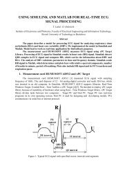
<strong>DESIGN</strong> <strong>OF</strong> <strong>PID</strong> <strong>CONTROLLER</strong> <strong>FOR</strong> <strong>PLC</strong>J. Paulusová, L. KörösiInstitute of Control and Industrial Informatics,Slovak University of Technology, Faculty of Electrical Engineering and Information TechnologyAbstractThis paper deals with <strong>PID</strong> algorithm for the Modicon Premium platform fromSchneider Electric. Based on real time samples measured by the <strong>PLC</strong> a model of theprocess was created in Matlab and then <strong>PID</strong> controller parameters were designed.The verification of algorithms on a real system (container with an unobstructeddrain) and the evaluation of control capabilities of the tested controller areintroduced. Paper deals with theoretical and practical methodology, offeringapproach for control design and its successful application.1 IntroductionProgrammable Logic Controller (<strong>PLC</strong>) devices have various advantages, such as highcomputing performance or the ability to communicate using different ports for different protocols(RS232, Ethernet) [2]. Relative complex and difficult ways of control and technical diagnostics canalso be handled by a compact <strong>PLC</strong>. Another positive feature, also from the <strong>PLC</strong> design perspective, isa simple combination of two basic types of control systems: distributed systems and integratedsystems. Thus, the advantages of both systems can be combined. An essential element of thesesystems is <strong>PLC</strong>. Components such as sensors, actuators, visualization features, etc. are connected via(digital/analogue) input and output modules or through communication channels. The abovementioned facts confirm that the <strong>PLC</strong> is suitable for complex solutions in the field of measurementand control.The ability of proportional integral (PI) and proportional integral derivative (<strong>PID</strong>) controllers tocompensate many practical industrial processes has led to their wide acceptance in industrialapplications. The easiest way for choice of either two or three controller parameters is perhaps bymaking use of tuning rules. Various surveys show that the use of <strong>PID</strong> algorithm is estimatedsomewhere between 90 and 95% in practice.This paper deals with design of <strong>PID</strong> algorithm and parameters for Modicon <strong>PLC</strong> TSX Premiumusing Matlab [5]. The <strong>PID</strong> controller has been designed for a real laboratory hydraulic system.2 Software – Unity Pro XLSchneider-Electric Unity Pro XL is a software environment for designing and programming ofSchneider-Electric <strong>PLC</strong>s. It is an unique and high performance multitask software, offered for theModicon M340, Premium, Quantum <strong>PLC</strong>‘s and Safety family. Unity Pro makes the best use of thegraphic and context-sensitive interfaces of Windows operating systems. It offers five IEC61131-3languages as standard. Each section of code can be programmed in the language of user’s choice, bestadapted to each processing operation. All of the edit, debugging and operation tools are accessiblewhatever language is used. The main benefit is in a complete set of functions and tools enablingmodelling of application structure on any machine or process structure. The program is split intoorganised function blocks by grouping: program sections, animation tables, operator screens andhyperlinks. Repetitive used basic functions are encapsulated in user function blocks DFB (DerivedFunction Block) in IEC61131-3 language. In addition, with the Unity EFB (Elementary FunctionBlocks) Toolkit, user know-how can be standardised by developing their own basic functions in Clanguage to supplement the Unity Pro library. An integrated library of application diagnostic isprovided by DFBs depending on function monitor permanent safety conditions and the evolution ofthe process over time. With the UDE, Unity is enhanced by specialised software for IT (InformationTechnology) developers in VBA (Visual Basic for Applications), VB (Visual Basic) or C++. It offersaccess to all Unity Pro software server objects for development of tailor-made solutions such as
creation of interfaces with an electrical CAD (Computer-Aided Design) or application automaticgenerator. Example of Unity Pro application is in Fig. 1.Figure 1: An example of Unity Pro application3 <strong>PID</strong> controller design<strong>PID</strong> control is a fundamental feedback control mechanism for various systems. It attempts tocorrect the difference between the measured and desired value – control error – using manipulatedvariable to suppress this difference to zero. The controller is represented by three components:proportional – represents the controller gain, depending on the error determines the actual response;integral – performs the sum of past deviations and derivative component – works with the rate ofchange of the error.Different <strong>PID</strong> function blocks are used in Unity Pro. These function blocks performinitialization in the first program cycle of the <strong>PLC</strong> program. Therefore they must be called in the mainprogram task, otherwise the initialization fails and outputs can have bad values [1].These function blocks have the following properties:- calculating the proportional, integral and differential component in its incremental form,- anti-windup reset,- direct or inverse action,- differential component to process value or deviation,- parameterization of the differential component transfer gain,- weight of the setpoint in the proportional component (reducing the overrun),- feed forward component for disturbance compensation,- dead zone on deviation,- incremental value and absolute value output,- upper and lower limit on the output signal (according to operating mode),- gradient limitation of the output signal,- output offset,- selecting manual/automatic mode,- tracking mode - bump less changeover between manual and automatic,- upper and lower setpoint limit.General block diagram of the <strong>PID</strong> function is shown in Fig. 2.
AutotuningSetpointProcess valueProcessingsetpointProcessingProcess valueLoopcontroller andcommandprocessingAutoManualProcessingOutputFeed forwardProcessingFeed ForwardManual commandTrackingFigure 2: <strong>PID</strong> function block diagramRepresentation of the <strong>PID</strong> function block (in Function Block Diagram - FBD language) withinputs and outputs is shown in Fig. 3. The illustration shows, that it is possible to assign SP, PV,MODE PARA FEED_FWD a YMAN tags (variables). Variables are explained in detail in Table 1.Figure 3: <strong>PID</strong> Function blockPossibility to create controllers with different combinations of P, I and D components isprovided by Boolean internal variables of the functional block en_p, en_i a en_d by setting theirvalues to 0 or 1.Table 1: LIST AND DESCRIPTION <strong>OF</strong> <strong>PID</strong> <strong>CONTROLLER</strong> VARIABLESI/OparametersInputsInputs-OutputsOutputsParameter Data type DescriptionSP REAL Reference valuePV REAL Process valueMODE Mode_<strong>PID</strong> Operating modePARA Para_<strong>PID</strong> ParametersFEED_FWD REAL Feed forwardYMANREALController output valuein manual modeY REAL Manipulated variableERR REAL Control deviationSTATUSStat_MAXMINState of manipulatedvariable
The structure and description of the data types of variables Mode_<strong>PID</strong>, Para_<strong>PID</strong>and Stat_MAXMIN are in Tab. 2.Table 2: LIST AND DESCRIPTION <strong>OF</strong> DATA STRUCTURES <strong>PID</strong> <strong>CONTROLLER</strong>StructureMode_<strong>PID</strong>ParameterDatatypeDescriptionman BOOL "1": Manual modehalt BOOL "1": Halt modeen_p BOOL "1": P enableden_i BOOL "1": I enableden_d BOOL "1": D enabledd_on_pvBOOL"1": D processing deviation, "0": Dprocessing process valuePara_<strong>PID</strong>gain REAL Gainti TIME Integral timetd TIME Derivation timetd_lag TIME Delay of Dymax REAL Upper limit of manipulated variableyminREALLower limit of manipulatedvariableStat_MAXMINqmaxqminBOOLBOOLUpper limit of manipulated variablereachedLower limit of manipulatedvariable reached4 Case studyHydraulic system (Fig. 4) consists of water tank with water reservoir, <strong>PLC</strong>, pressure transmitter,frequency inverter and a pump [3].Honeywell ST 3000 S900 pressure transmitter was used to measure the water level in the tank.It is a reliable and intelligent transmitter [4]. It offers the possibility of measuring pressure, absolutepressure, differential pressure and level. The signal from the transmitter is connected to the <strong>PLC</strong>analogue input card.The transfer of water from the water reservoir into the water tank was making use of amonoblock centrifugal pump with threaded neck from CALPEDA manufacturer. The pump type isCALPEDA NM 2/AE.The pump is controlled by a compact inverter PowerFlex 40 from Allen-Bradley, which isconnected to the <strong>PLC</strong> analogue output card.PowerFlex 40 has a standard control panel display, touch keypad and potentiometer. Theinverter also includes LEDs to indicate the current status of the inverter.
Figure 4: Block diagram of the hydraulic system (<strong>PLC</strong>, inverter, pump, pressure transmitter, tank andreservoir)5 Simulation ResultsThe K p , T i and T d parameters has been obtained by Ziegler-Nichols method [6].Transfer function of <strong>PID</strong> controller is:GR( s)( s)I ⎛ 1( ) ⎟ ⎞= P + + Ds = K p⎜ + + Tds s ⎝ Tis ⎠U= 1 s(1)EThe procedure is as follows:1) Turn off the I-term and the D-term in the controller.2) Turn P to zero, and then increase it slowly, while looking at time responses of the output variable(y) or - some times better - the output of the controller, u. Increase P until the output exhibits sustainedoscillations (see Fig. 5 - violet, P=6.5)3) At this "quasi steady-state" point we have reached the critical gain, called P=P K , and period ofoscillations, T K =5.34 s.4) Then the T i and T d should be turned on with the following configuration values (see the Tab. 3).Figure 5: Time responses of the output variable by different parameter P (I=0, D=0)
Table 3: CLOSED-LOOP CALCULATIONS <strong>OF</strong> <strong>PID</strong> PARAMETERSK p T i T dP controller P K / 2 - -PI controller P K / 2.2 T K / 1.2 -<strong>PID</strong> controller P K / 2.7 T K / 2 T K / 8From Tab. 3, K p , T i , and T d can be calculated for all three types of controllers. The results areshown in (Tab. 4 and Tab. 5).Table 4: PARAMETERS <strong>OF</strong> <strong>PID</strong> <strong>CONTROLLER</strong> (SEE EQ. 1)K p T i T dP controller 3.25 - -PI controller 2.95 4.45 -<strong>PID</strong> controller 3.82 2.67 0.67TABLE 5: PARAMETERS <strong>OF</strong> <strong>PID</strong> <strong>CONTROLLER</strong> (SEE EQ. 1)P I DP controller 3.25 - -PI controller 2.95 0.66 -<strong>PID</strong> controller 3.82 1.43 2.55At first glance, we can see from the table that the PI controller has T i greater than K p , and intheory we know that for the most applications it is the opposite.Also T d is high value in comparison with the other parameters and such tuned <strong>PID</strong> controller cancreate oscillations of the output variable around the desired variable.Figure 6: Time responses of the output variable under <strong>PID</strong> controller (Ziegler-Nichols method)
Time responses of the output variable under Ziegler-Nichols controller are shown in Fig. 6.Designed PI controller (Ziegler-Nichols) is compared with PI controller, whose parameters weredesigned by experimental methods (P=2.6, I=3.6). Time responses of the output variable under bothcontrollers are shown in Fig. 7.Figure 7: Comparison of time responses of the output variable under PI controller (Ziegler-Nicholsmethod and experimental method)6 ConclusionThis paper deals with control of a real system – a container with an unobstructed drain. <strong>PID</strong>controller for control of hydraulic system was designed by Ziegler-Nichols method and experimentalmethod. Each of the designed control loops were verified by a simulation model in Matlab-Simulinkbefore a test on the real system.ACKNOWLEDGMENTThis paper was supported by the Slovak Scientific Grant Agency VEGA, Grant no. 1/1105/12,Grant No. 1/2256/12 and Grant No. 1/1241/12.References[1] A. Pulen. Implementation of automatic design of <strong>PID</strong> controller in the <strong>PLC</strong>. Master Thesis, FEISTU, Slovak Republic, May 2009.[2] L. Mrafko, M. Mrosko, L. Körösi: <strong>PLC</strong> a ich programovanie. Available on internet:[3] Frekvenční měnič PowerFlex 40. Available on internet:[4] Inteligentný vysielač pretlaku, absolútneho tlaku, tlakovej diferencie a hladiny ST 3000. Availableon internet: [5] Modicon TSX Premium <strong>PLC</strong>s. Available on internet:
[6] Štruktúry a formy spojitých <strong>PID</strong> regulátorov. Available on internet:Jana Paulusová and Ladislav KörösiInstitute of Control and Industrial Informatics,Faculty of Electrical Engineering and Information Technology,Slovak University of Technology,Ilkovičova 3, 812 19 Bratislava, Slovak Republice-mail: jana.paulusova@stuba.sk, ladislav.korosi@stuba.sk