gui for the reconstruction of 3d coordinates - Humusoft
gui for the reconstruction of 3d coordinates - Humusoft
gui for the reconstruction of 3d coordinates - Humusoft

Create successful ePaper yourself
Turn your PDF publications into a flip-book with our unique Google optimized e-Paper software.
GUI FOR THE RECONSTRUCTION OF 3D COORDINATES<br />
Libor Boleček, Václav Říčný<br />
Department <strong>of</strong> Radio Electronics, Brno University <strong>of</strong> Technology<br />
Purkyňova 118, 612 00 BRNO<br />
Abstract<br />
The article deals with design <strong>of</strong> user interface <strong>for</strong> <strong>reconstruction</strong> <strong>of</strong> 3D <strong>coordinates</strong>.<br />
The interface allows automatic creation model <strong>of</strong> <strong>the</strong> scene <strong>for</strong> inexpert user. On <strong>the</strong><br />
o<strong>the</strong>r hand, program provides possibilities set <strong>of</strong> many attributes during process <strong>of</strong><br />
<strong>reconstruction</strong> <strong>for</strong> expert user. Besides calculate <strong>of</strong> 3D <strong>coordinates</strong> interface can serve<br />
<strong>for</strong> creation <strong>of</strong> depth map. The application user familiar math equations as well as<br />
some proposed modification. The interface allows using different method in each<br />
steps <strong>of</strong> <strong>the</strong> <strong>reconstruction</strong>, <strong>the</strong>re<strong>for</strong>e it can serve as education program.<br />
1 Introduction: Reconstruction <strong>of</strong> 3D <strong>coordinates</strong><br />
The <strong>reconstruction</strong> <strong>of</strong> a 3D model <strong>of</strong> a scene is actual and perspective topic in computer vision.<br />
The reconstructed model can be used in many applications in various areas– especially in robotics,<br />
civil and building engineering, medicine, etc. The output <strong>of</strong> <strong>the</strong> <strong>reconstruction</strong> are three spatial<br />
<strong>coordinates</strong> in a selected coordinate system. Related problem is <strong>the</strong> creation <strong>of</strong> a depth map <strong>of</strong> a scene<br />
which results in a grayscale image. Intensity <strong>of</strong> each pixel is equivalent to <strong>the</strong> relative depth.<br />
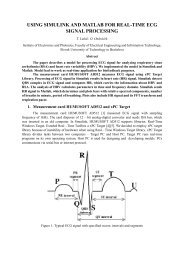
In order to build <strong>the</strong> model, <strong>the</strong>re are several main procedures which need to be executed<br />
successively. Appropriate flowchart is shown in Fig. 1. This process is based on camera calibration<br />
and finding <strong>of</strong> <strong>the</strong> corresponding points. The interior and exterior orientation <strong>of</strong> camera must be<br />
obtained. The interior orientation represents <strong>the</strong> properties <strong>of</strong> camera (f, u o , v o , s) and its distortion.<br />
Interior parameters are expressed by calibration matrix K[13]<br />
⎡⎡fu<br />
s u0⎤⎤<br />
K =<br />
⎢⎢<br />
0 fv<br />
v<br />
⎥⎥. (1)<br />
⎢⎢<br />
0 ⎥⎥<br />
⎢⎢⎣⎣0 0 1⎥⎥⎦⎦<br />
Where f u and f v represent <strong>the</strong> focal lengths in pixel, (u o , v o ) represent <strong>the</strong> <strong>coordinates</strong> <strong>of</strong> principal point,<br />
s represents <strong>the</strong> skew. In literature, we can find many methods <strong>for</strong> camera calibration [1], [2], [3]. The<br />
exterior orientation represents <strong>the</strong> relation between camera positions given by rotation matrix R and<br />
translation vector T. Then <strong>the</strong> relation (2) expresses calculation <strong>of</strong> 3D coordinate [14].<br />
⎡⎡ P3⋅x<br />
i<br />
−P1<br />
⎤⎤<br />
⎢⎢<br />
3<br />
y<br />
⎥⎥<br />
⎢⎢<br />
P ⋅<br />
i<br />
−P2<br />
⎥⎥ ⋅ X = 0, (2)<br />
⎢⎢P' 3⋅x' i<br />
−P'<br />
⎥⎥<br />
1<br />
⎢⎢ ⎥⎥<br />
⎣⎣P' 3⋅y<br />
'<br />
i<br />
−P'<br />
2⎦⎦<br />
where P 1 , P 2 , P 3 and P’ 1 , P’ 2 , P’ 3 are rows <strong>of</strong> <strong>the</strong> projection matrix P, P’. The projection matrix is<br />
obtained as P = [I | 0] and P = [R | T]. Fur<strong>the</strong>r x i , y i , x’ i and y’ i are image <strong>coordinates</strong> <strong>of</strong> corresponding<br />
points. Vector X contains <strong>the</strong> resulting spatial <strong>coordinates</strong> <strong>of</strong> points. The system <strong>of</strong> equations can be<br />
solves with a linear least squares solution [14].<br />
The fundamental task is achievement image correspondents. The image correspondents are used<br />
in each subsequent step <strong>of</strong> <strong>the</strong> <strong>reconstruction</strong>. The location <strong>the</strong> significant points in <strong>the</strong> left and right<br />
images is first <strong>the</strong> step to get <strong>the</strong> correspondences. The significant points are pixels with salient<br />
properties which can be detected in both images. We need to find <strong>the</strong> same pixel in each image.<br />
Algorithms <strong>for</strong> this objective are <strong>of</strong>ten solved and many papers <strong>of</strong> this problem exist [4], [5].<br />
Moreover, elimination <strong>of</strong> false correspondents is important, too. We propose fast elimination <strong>of</strong> false<br />
correspondences based on geometric constraints and extremities.<br />
The above described approaches can be used only <strong>for</strong> <strong>reconstruction</strong> <strong>of</strong> spatial <strong>coordinates</strong> <strong>of</strong><br />
points, <strong>the</strong>se, which we are able to find in both images. This task it is a very difficult <strong>for</strong> a point, which<br />
belongs to an area with regular textures or without contrast. We proposed and tested a method based
on relation between arbitrary selected points (by user) and feature points in nearby. The main idea uses<br />
hypo<strong>the</strong>sis, that small areas in image lies in same depth.<br />
Establised image<br />
correspondences<br />
Determine<br />
fundamental<br />
matrix F<br />
Interior calibration<br />
Determine<br />
essential matrix F<br />
Exterior<br />
calibration:<br />
Determine 3D<br />
point coordinate<br />
Figure 1: The general flowchart <strong>of</strong> designed system <strong>for</strong> <strong>reconstruction</strong> 3D model.<br />
2 Proposed interface<br />
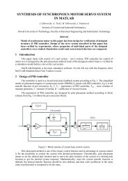
Proposed interface will serve as tools in laboratory lessons. The interface is shown Figure 2.<br />
The application allows per<strong>for</strong>m all steps necessary <strong>for</strong> <strong>reconstruction</strong> <strong>of</strong> 3D <strong>coordinates</strong> describe in<br />
section 1 (see figure 1). The application uses concurrently known ma<strong>the</strong>matical relations, open source<br />
MATLAB algorithms or toolbox (<strong>for</strong> example <strong>for</strong> calculate interior calibration) and own proposed<br />
procedures publicated in [10]. The inputs are two picture <strong>of</strong> <strong>the</strong> same scene taken from different<br />
positions. In first phase we need find correspondences between pictures. The user can load<br />
correspondences, automatically find new correspondences various methods<br />
• Speeded up robust features SURF [7],<br />
• Scale-Invariant Keypoints SIFT [8],<br />
• Harris corner detector [16].<br />
Subsequently, user can select various types <strong>of</strong> image representation used <strong>for</strong> finding <strong>of</strong><br />
correspondences<br />
• Grayscale,<br />
• RGB model with true colors,<br />
• RGB model with false colors.<br />
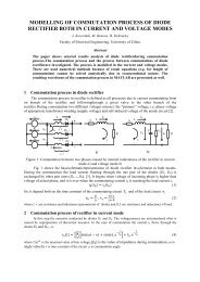
Image in false colors is obtained using process pseudo coloring from grayscale image. In false colors,<br />
image has more contrast. This fact can be useful. This possibility will examined and described in detail<br />
in our future publication. In designed interface was implemented algorithm <strong>for</strong> pseudo coloring<br />
proposed in [12]. One image in false colors is shown in Figure 2. Next possibility is determination<br />
correspondences manually. Last selectable parameter <strong>of</strong> <strong>the</strong> correspondences finding is number <strong>of</strong><br />
correspondences. Subsequently, <strong>the</strong> user can save founded correspondences.
Figure 1: Image in false color, obtained by algorithm implemented in interface (picture is taken from<br />
[15]).<br />
The application allows elimination <strong>of</strong> false correspondences by method proposed in [10]. Next step is<br />
determination <strong>of</strong> <strong>the</strong> interior calibration <strong>of</strong> <strong>the</strong> camera. The user can calibration matrix load from disc,<br />
enter manually or calculate using MATLAB Toolbox Calib [11]. In subsequent step, <strong>the</strong> user need<br />
calculate exterior calibration <strong>of</strong> <strong>the</strong> camera.<br />
Now user has all data required <strong>for</strong> calculation <strong>of</strong> <strong>the</strong> model <strong>of</strong> <strong>the</strong> scene or <strong>for</strong> calculation depth map.<br />
The results are display on <strong>the</strong> second half <strong>of</strong> <strong>the</strong> interface. The interface allows various representations<br />
<strong>of</strong> <strong>the</strong> result. First <strong>of</strong> <strong>the</strong>m is graphic representation by ground plan. Second one is graphic<br />
representation as 3D model. Next possibility is numeric representation <strong>of</strong> <strong>the</strong> spatial position <strong>of</strong> <strong>the</strong><br />
concrete corresponding pixel. Important part <strong>of</strong> <strong>the</strong> application is <strong>reconstruction</strong> <strong>of</strong> image point<br />
selected by user. The user select point in first image and finding <strong>of</strong> corresponding in second image can<br />
be problem if point belongs to area without contrast. In this issue regular used methods can fail. We<br />
proposed approach which can solve this problem. The algorithm is publicated in [10] and implemented<br />
in this interface.<br />
In <strong>the</strong> process <strong>of</strong> creating depth map, user can select, whe<strong>the</strong>r want use some <strong>of</strong> local based method<br />
(<strong>for</strong> example Sum <strong>of</strong> Absolute Differences SAD, Sum <strong>of</strong> Squared Differences SSD, Ratio Image<br />
Uni<strong>for</strong>mity RUI, Mutual In<strong>for</strong>mation MI) or method based on founded correspondences and image<br />
segmentation.<br />
Figure 3: Interface <strong>for</strong> <strong>reconstruction</strong> <strong>of</strong> 3D <strong>coordinates</strong>.
3 Results<br />
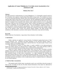
In this section, we are going to present results obtained by using proposed application. Figure 4<br />
shows results <strong>of</strong> <strong>the</strong> elimination <strong>of</strong> <strong>the</strong> false correspondences. In <strong>the</strong> figure 5 are presented some 3D<br />
model <strong>of</strong> <strong>the</strong> scene. In <strong>the</strong> first column is picture <strong>of</strong> <strong>the</strong> scene and in second column are <strong>the</strong>irs model.<br />
Figure 6 show some depth map obtained by algorithm implemented in interface.<br />
Figure 4: Image correspondences be<strong>for</strong>e and after use algorithm <strong>for</strong> elimination false correspondences<br />
(picture is taken from [15]).<br />
Figure 5: In first column are images <strong>of</strong> <strong>the</strong> scene. In second column are resulting <strong>reconstruction</strong>. Red<br />
marks represent location <strong>of</strong> selected point in space.<br />
The application utilizes possibility <strong>of</strong> design simple GUI in MATLAB. Next advantage is opportunity<br />
to use functions integrated in MATLAB, which makes work simpler. The application combines our<br />
own algorithm with open source algorithm. The interface should serve <strong>for</strong> students and <strong>the</strong>ir
introduction with topic <strong>of</strong> <strong>the</strong> <strong>reconstruction</strong> <strong>of</strong> spatial <strong>coordinates</strong>. On <strong>the</strong> second hand interface can<br />
use even <strong>for</strong> simple execution some tests <strong>of</strong> proposed algorithms.<br />
Figure 6: Depth map obtained by algorithm implemented to interface.<br />
ACKNOWLEDGEMENT<br />
This work was supported by <strong>the</strong> grant project <strong>of</strong> <strong>the</strong> Czech Science Foundation no.<br />
102/10/1320 – Research and modeling <strong>of</strong> advanced methods <strong>of</strong> image quality evaluation, by<br />
<strong>the</strong> project Signal processing in mobile and wireless communication systems FEKT-S-11-12<br />
and by MEYS <strong>of</strong> <strong>the</strong> Czech Republic national project no. LD12005 “Quality <strong>of</strong> Experience<br />
aspects <strong>of</strong> broadcast and broadband multimedia services (QUALEXAM)”. The described<br />
research was per<strong>for</strong>med in laboratories supported by <strong>the</strong> SIX project; <strong>the</strong> registration number<br />
CZ.1.05/2.1.00/03.0072, <strong>the</strong> operational program Research and Development <strong>for</strong> Innovation.<br />
References<br />
[1] A. Gruen, A., H. A. Beyer, S. Shafer, O.D. Faugeras, P. Wrobel and R.G Willson, Calibration and Orientation <strong>of</strong> Cameras in<br />
Computer Vision, first. T.S.Huang. Germany: Springer, 2001, 235 p. Springer Series inIn<strong>for</strong>mation Sciences, 34. ISBN 3-540-65283-3.<br />
[2] Z. Zhang, "Flexible camera calibration by viewing a plane from unknown orientations," Computer Vision, 1999. The Proceedings <strong>of</strong><br />
<strong>the</strong> Seventh IEEE International Conference on , vol.1, no., pp.666-673 vol.1, 1999 doi: 10.1109/ICCV.1999.791289 URL:<br />
http://ieeexplore.ieee.org/stamp/stamp.jsp?tp=&arnumber=791289&isnumber=17134<br />
[3] P.R.S. Mendonca, R. Cipolla, "A simple technique <strong>for</strong> self-calibration," Computer Vision and Pattern Recognition, 1999. IEEE<br />
Computer Society Conference on. , vol.1, no., pp.2 vol. (xxiii+637+663), 1999 doi: 10.1109/CVPR.1999.786984 URL:<br />
http://ieeexplore.ieee.org/stamp/stamp.jsp?tp=&arnumber=786984&isnumber=17045<br />
[4] T. Tuytelaars, K. Mikolajczyk, “Local invariant feature detectors: a survey”. Found. Trends. Comput. Graph. Vis. 3, 3 (July 2008),<br />
177-280. DOI=10.1561/0600000017 URL: http://dx.doi.org/10.1561/0600000017<br />
[5] G. Steffen, T. Hollerer, M. Turk, “Evaluation <strong>of</strong> Interest Point Detectors and Feature Descriptors <strong>for</strong> Visual Tracking”. International<br />
Journal <strong>of</strong> Computer Vision [online]. 2011-09-01, vol. 94(issue. 3), 335-360 [cit. 2012-02-07]. DOI: 10.1007/s11263-011-0431-5.<br />
URL: http://www.springerlink.com/content/k062m660066wl2j6/<br />
[6] R. Kalia, L. Keun-Dong, B.V.R. Samir, J. Sung-Kwan, O. Weon-Geun, "An analysis <strong>of</strong> <strong>the</strong> effect <strong>of</strong> different image preprocessing<br />
techniques on <strong>the</strong> per<strong>for</strong>mance <strong>of</strong> SURF: Speeded Up Robust Features," Frontiers <strong>of</strong> Computer Vision (FCV), 2011 17th Korea-Japan<br />
Joint Workshop on , vol., no., pp.1-6, 9-11 Feb. 2011 doi: 10.1109/FCV.2011.5739756 URL:<br />
http://ieeexplore.ieee.org/stamp/stamp.jsp?tp=&arnumber=5739756&isnumber=5739698<br />
[7] H. Bay, T. Tuytelaars, L. V. Gool, “SURF: Speeded up robust features,” Proc. <strong>of</strong> <strong>the</strong> 9th European Conf. Computer Vision, pp. 404-<br />
417, 2006, URL: http://www.springerlink.com/content/e580h2k58434p02k/fulltext.pdf<br />
[8] D. Lowe, “Distinctive Image Features from Scale-Invariant Keypoints,” International Journal <strong>of</strong> Computer Vision, 60(2), pp.91-<br />
110, 2004. URL: http://www.cs.ubc.ca/~lowe/papers/ijcv04.pdf<br />
[9] L. Chuan, Z. Jinjin, D. Chuangyin, Z. Hongjun; , "A Method <strong>of</strong> 3D Reconstruction from Image Sequence," Image and Signal<br />
Processing, 2009. CISP '09. 2nd International Congress on , vol., no., pp.1-5, 17-19 Oct. 2009 doi: 10.1109/CISP.2009.5305647 URL:<br />
http://ieeexplore.ieee.org/stamp/stamp.jsp?tp=&arnumber=5305647&isnumber=5300807<br />
[10] L. Boleček, V. Říčný, M. Slanina, M.“Fast Method <strong>for</strong> Reconstruction <strong>of</strong> 3D Coordinates“. In TSP 2012. Praha: 2012.s. 740-<br />
744. ISBN: 978-1-4673-1116- 8.<br />
[11] Camera Calibration Toolbox <strong>for</strong> Matlab [program].: Jean-Yves Bouguet, Last updated July 9th, 2010. URL:<br />
http://www.vision.caltech.edu/bouguetj/calib_doc/.<br />
[12] T. Lehman, A. Kaser, R. Repges „A simple parametric equation <strong>for</strong> pseudocoloring grey scale images keeping <strong>the</strong>ir original brightness<br />
progression“ [online]. 1993-1996 [cit. 20011-4-11]. Dostupný z WWW: < http://ganymed.imib.rwth-aachen.de/deserno/pspdf/IVC_1997-<br />
15%283%29251-257.pdf>.<br />
[13] E.M. Mikhail, J.S. Be<strong>the</strong>l, J.CH. McGlone, Intruduction to Modern Photogrammetry. New York : John Wiley & Sons, 2001. 479 s.<br />
ISBN 0-471-30924-9.<br />
[14] Stančík, P. Optoelektronické a fotogrammetrické měřící systémy. Brno: Vysoké učení technické v Brně, Fakulta elektrotechniky a<br />
komunikačních technologií, 2008. 89p. Supervisor <strong>of</strong> <strong>of</strong> <strong>the</strong> dissertation pr<strong>of</strong>. Ing. Václav Říčný, CSc.
[15] http://vision.ucla.edu/MASKS/<br />
[16] X. Zhang “Detection <strong>of</strong> moving corners in dynamic images”. In proceeding <strong>of</strong>: Industrial Electronics, 1994. Symposium Proceedings,<br />
ISIE '94., 1994 IEEE International Symposium on, ISBN: 0-7803-1961-3<br />
Author1<br />
Ing. Libor Boleček<br />
Department <strong>of</strong> Radio Electronics, Brno Univ. <strong>of</strong> Technology, Purkyňova 118, 612 00 BRNO<br />
E-mail: xbolec01@stud.feec.vutbr.cz