Pilot Study, Fault Identification and Effect of Maintenance
Pilot Study, Fault Identification and Effect of Maintenance
Pilot Study, Fault Identification and Effect of Maintenance

Create successful ePaper yourself
Turn your PDF publications into a flip-book with our unique Google optimized e-Paper software.
Diesel Vehicle Emissions – In-Service Emissions Testing – <strong>Pilot</strong> <strong>Study</strong>, <strong>Fault</strong> <strong>Identification</strong> <strong>and</strong> <strong>Effect</strong> <strong>of</strong> <strong>Maintenance</strong> - Appendices<br />
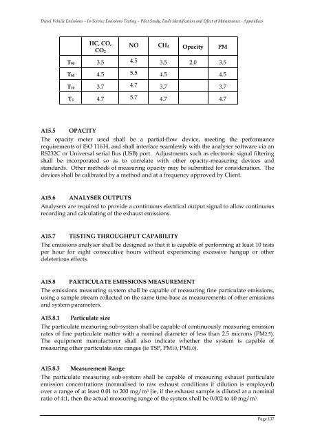
HC, CO,<br />
CO 2<br />
NO CH 4 Opacity PM<br />
T 90 3.5 4.5 3.5 2.0 3.5<br />
T 95 4.5 5.5 4.5 4.5<br />
T 10 3.7 4.7 3.7 3.7<br />
T 5 4.7 5.7 4.7 4.7<br />
A15.5 OPACITY<br />
The opacity meter used shall be a partial-flow device, meeting the performance<br />
requirements <strong>of</strong> ISO 11614, <strong>and</strong> shall interface seamlessly with the analyser s<strong>of</strong>tware via an<br />
RS232C or Universal serial Bus (USB) port. Adjustments such as electronic signal filtering<br />
shall be incorporated so as to correlate with other opacity-measuring devices <strong>and</strong><br />
st<strong>and</strong>ards. Other methods <strong>of</strong> measuring opacity may be submitted for consideration. The<br />
devices shall be calibrated by a method <strong>and</strong> at a frequency approved by Client.<br />
A15.6 ANALYSER OUTPUTS<br />
Analysers are required to provide a continuous electrical output signal to allow continuous<br />
recording <strong>and</strong> calculating <strong>of</strong> the exhaust emissions.<br />
A15.7 TESTING THROUGHPUT CAPABILITY<br />
The emissions analyser shall be designed so that it is capable <strong>of</strong> performing at least 10 tests<br />
per hour for eight consecutive hours without experiencing excessive hangup or other<br />
deleterious effects.<br />
A15.8 PARTICULATE EMISSIONS MEASUREMENT<br />
The emissions measuring system shall be capable <strong>of</strong> measuring fine particulate emissions,<br />
using a sample stream collected on the same time-base as measurements <strong>of</strong> other emissions<br />
<strong>and</strong> system parameters.<br />
A15.8.1 Particulate size<br />
The particulate measuring sub-system shall be capable <strong>of</strong> continuously measuring emission<br />
rates <strong>of</strong> fine particulate matter with a nominal diameter <strong>of</strong> less than 2.5 microns (PM2.5).<br />
The equipment manufacturer shall also indicate whether the system is capable <strong>of</strong><br />
measuring other particulate size ranges (ie TSP, PM10, PM1.0).<br />
A15.8.3 Measurement Range<br />
The particulate measuring sub-system shall be capable <strong>of</strong> measuring exhaust particulate<br />
emission concentrations (normalised to raw exhaust conditions if dilution is employed)<br />
over a range <strong>of</strong> at least 0.01 to 200 mg/m 3 (ie, if the exhaust sample is diluted at a nominal<br />
ratio <strong>of</strong> 4:1, then the actual measuring range <strong>of</strong> the system shall be 0.002 to 40 mg/m 3 .<br />
Page 137