Create successful ePaper yourself
Turn your PDF publications into a flip-book with our unique Google optimized e-Paper software.
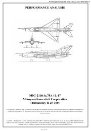
<strong>Mig</strong>-<strong>21</strong>-FM-Identification-Rev. 14<br />
Sustained load factor tables.<br />
Once thrust and null-lift drag law have been approximated as described previously, the next step is to<br />
determine Lift and Drag coefficient values for higher incidence values.<br />
The aim of the analysis of the sustained load factor table is to define the Drag coefficient for incidence<br />
values higher than the one deduced from level flight acceleration.<br />
First of all, figures from the manual are analyzed in order translate them in tables giving the load<br />
factor sustained (Extra Specific Power = 0) with full after burner for a given aircraft configuration, a<br />
given altitude and a give mach number.<br />
The aircraft configuration is assumed to be the same as previously: gross weight of 8,000 kg , drag<br />
index of 12 (two IR missile).<br />
For each value of Altitude, Mach number and load factor, the equation system describing the equality<br />
of Lift and Apparent Weight on one side and Thrust and Drag on the other side has to be solved to find<br />
the corresponding value of the Drag coefficient:<br />
(6.1)<br />
This simplified set of equation can be solved analytically, but it is its only advantage as it assume the<br />
thrust force is applied along the speed vector, and this approximation can only be accepted only for<br />
very small incidence angle (up to 5 degrees) that are not the one corresponding the flight conditions<br />
such as the one described in “sustained load factor diagram” analyzed here.<br />
So I chose to solve numerically the more precise equations set:<br />
This allows the computation, for all points extracted from the figures to compute the value of the k<br />
coefficient (defined by formula (5.1) here).<br />
(6.4)<br />
Page - 14