Operation - Weber Ultrasonics GmbH
Operation - Weber Ultrasonics GmbH
Operation - Weber Ultrasonics GmbH

You also want an ePaper? Increase the reach of your titles
YUMPU automatically turns print PDFs into web optimized ePapers that Google loves.
<strong>Operation</strong>s Manual<br />
for ultrasonic generators from the series<br />
SONIC DIGITAL LC TD/SD<br />
Version Premium & Basic<br />
CLEANING TECHNOLOGY<br />
Art.Nr: 9000.1102 GB
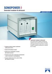
SONIC DIGITAL LC - ultrasonic generators<br />
Contents<br />
Introduction 03<br />
www.weber-ultrasonics.com<br />
Safety instructions 03<br />
Assembly 05<br />
<strong>Operation</strong> 12<br />
Default settings in the Settings menu 17<br />
Error messages and troubleshooting 19<br />
Maintenance 20<br />
Specifications 20, 21<br />
Notes on transducer systems 22<br />
Warranty 23<br />
CE conformity 23<br />
Index 24<br />
Service telephone number 24<br />
Spare parts 24<br />
Production, Sale and Service:<br />
<strong>Weber</strong> <strong>Ultrasonics</strong> <strong>GmbH</strong> Phone: +49 (0) 72 48 / 92 07-0<br />
Im Hinteracker 7 Fax: +49 (0) 72 48 / 92 07-11<br />
76307 Karlsbad-Ittersbach mail@weber-ultrasonics.de<br />
Germany<br />
www.weber-ultrasonics.de
SONIC DIGITAL LC - ultrasonic generators<br />
Introduction<br />
Dear Customer,<br />
Thank you for purchasing this <strong>Weber</strong> <strong>Ultrasonics</strong> product. You have chosen a first-class product<br />
that was developed using the latest technology.<br />
www.weber-ultrasonics.com<br />
It is vital that you read these operating instructions and follow them carefully before installing<br />
or commissioning your product. Failure to observe these instructions can present a risk to life.<br />
Units may be operated by trained personnel only. Failure to comply with this will result in a loss<br />
of warranty rights.<br />
The device may only be operated and maintained by personnel who have read and understood this operating<br />
manual and are familiar with the applicable legal regulations for accident prevention and workplace safety.<br />
Safety instructions<br />
Before starting up your device, please read through the following instructions carefully, both for your own safety and for<br />
the safety of the device.<br />
Keep this manual where it can be readily accessed by all systems users.<br />
Installation is to be carried out by qualified technical personnel only!<br />
The ultrasonic generator is to be operated by properly trained personnel only!<br />
Due to the way it operates, additional safety measures must be taken if the device is to be used in areas posing an<br />
explosion risk.<br />
<strong>Ultrasonics</strong> energy is converted into thermal energy during operation. It is essential to ensure that this heat is able to<br />
dissipate. Depending on the cleaning medium in use, an unchecked heat build-up could result in the formation of explosive<br />
or readily combustible vapors!<br />
Only use bath liquids which comply with environmental standards and are tested and approved<br />
for use in ultrasonic cleaning systems.<br />
The electromagnetic compatibility corresponds to the standards and regulations listed in the specifications.<br />
All necessary settings were either made in the factory or are described in this handbook. However, should problems occur<br />
on start-up, please do not make any prohibited adjustments to the device, as this would endanger your warranty rights. If<br />
in doubt, please contact our technical service staff.<br />
Please contact our technical service if at all in doubt.<br />
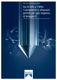
Never allow ultrasonics to run in a dry or partially filled bath!<br />
Always check that the bath is filled up to the proper level marking.
SONIC DIGITAL LC - ultrasonic generators<br />
Display:<br />
incorrect<br />
correct<br />
www.weber-ultrasonics.com<br />
Never run the transducers dry. The liquid surrounding the transducers should never exceed a maximum temperature<br />
of 90°C. It may only contain chemicals which do not attack stainless steel 1.4571. The maximum chloride content<br />
of this liquid may not exceed 40 ppm, as pitting corrosion may otherwise occur.<br />
Work inside the device may only be carried out to the extent described and, as with the electrical connection, should only<br />
be performed by skilled personnel. When performing such work, the ultrasonic generator must be completely disconnected<br />
from the mains (unplug the mains connection).<br />
Inputs or outputs that are used for controlling or monitoring purposes should be twisted and shielded.<br />
The device must not be in close proximity to electrically charged components or cables.<br />
The shielding should be connected to the generator‘s earth on one side of the generator.<br />
Attention: All connections for the signal or control lines are galvanically connected to the generator.<br />
Always observe any warnings or instructions given on the device itself.<br />
The device must always be disconnected from the mains before cleaning or when installing/uninstalling an option.<br />
Do not use liquid cleaners or sprays. Only use a damp cloth.<br />
Never operate the device in areas where moisture could penetrate the device.<br />
The platform for the device must be sufficiently stable, as the device being jolted or falling could cause severe damage.<br />
Ensure that the power supply specifications given on the device are met.<br />
Only those transducers which have the correct frequency, power output and dimensions may be used with this generator.<br />
HF cables from the generator to the transducer as well as mains cables to the generator may not be rolled up if they are<br />
too long. Instead, they must be shortened to the required length due to the risk of overheating.<br />
With the exception of the permitted tasks listed in the handbook, you should never attempt to repair or modify<br />
the device yourself.<br />
In the following cases you should disconnect the device from the mains and contact a qualified service engineer:<br />
· If the mains cable or plug is damaged<br />
· If liquid has penetrated into the device<br />
· If the device has fallen over or the housing is damaged<br />
· If the device displays noticeably different behaviour than standard operation<br />
Attention: Repairs and modifications may only be carried out by competent, skilled personnel.
SONIC DIGITAL LC - ultrasonic generators<br />
Assembly<br />
Installation location instructions 06<br />
Power supply 06<br />
www.weber-ultrasonics.com<br />
Connections on the back of the generator 07<br />
Assignment of the HF connection socket 08<br />
Interface description 10
SONIC DIGITAL LC - ultrasonic generators<br />
Notes on the installation location<br />
During operation the generator will get very hot. If the generator cannot dissipate this heat sufficiently, it will<br />
display an error message due to excess temperature (see also the “OVERTEMPERATURE” error description).<br />
In addition, ambient temperatures of over 30°C should be avoided.<br />
Choose a suitable location that will protect the device from moisture, water, excessive sunlight and heat.<br />
www.weber-ultrasonics.com<br />
Attention:<br />
• Choose a location that will prevent steam or any other aggressive vapours<br />
from penetrating the device.<br />
• Over a period of time, chemically contaminated ambient air can lead to<br />
the device being irreparably damaged.<br />
Power supply<br />
The ultrasonic generator draws its power (230 V AC and 50/60 Hz) via the connection cable.<br />
It has an internal main fuse (10 AF).<br />
If you need to change the fuses, unscrew the bottom of the housing.<br />
ATTENTION:<br />
• For safety reasons, always disconnect the unit from the mains before changing fuses<br />
• Plug racks into earthed sockets only<br />
• Always replace blown fuses with new fuses of the same type<br />
• This should only be performed by qualified, skilled personnel
SONIC DIGITAL LC - ultrasonic generators<br />
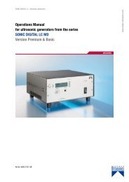
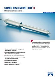
Connections on the back of the generator<br />
www.weber-ultrasonics.com<br />
Version TD<br />
Depending on whether you have purchased version TD (submersible transducer) or SD (rod-style transducer),<br />
you will see different HF connection sockets on the back of the casing.<br />
The TD version has an 8-pole Amphenol socket.<br />
The SD version uses a 4-pole Amphenol socket.<br />
For details on the pin assignment of the sockets, please refer to the following two pages.
SONIC DIGITAL LC - ultrasonic generators<br />
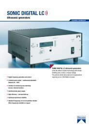
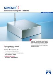
HF-Connection socket –<br />
PIN assignment for submersible transducers (TD version):<br />
Connection PIN A - NC – Not assigned<br />
Connection PIN B - NC – Not assigned<br />
Connection PIN C - NC – Not assigned<br />
Connection PIN D - HF – Transducer (“hot” connection)<br />
Connection PIN E - HF – Transducer minus/ground<br />
Connection PIN F - Is jumpered with PIN “E” in the connection plug<br />
Connection PIN G - Is jumpered with PIN “E” in the connection plug<br />
Connection PIN H - PE conductor for transducer PE<br />
www.weber-ultrasonics.com
SONIC DIGITAL LC - ultrasonic generators<br />
HF-Connection socket –<br />
PIN assignment for rod-style transducers (SD version):<br />
Connection PIN 1 - HF – Transducer “hot” connection<br />
Connection PIN 2 - HF – Transducer minus / ground<br />
Connection PIN 3 - Is jumpered with PIN “2” in the connection plug<br />
Connection PIN 4 - PE conductor for transducer PE<br />
www.weber-ultrasonics.com<br />
Attention: Only use the cables provided/recommended by the manufacturer<br />
Only use shielded transducer connection cables<br />
Connect the shielding to the PE conductor on the generator side.<br />
Only use cables with sufficient profile.<br />
Minimum profile 1.5 mm².
SONIC DIGITAL LC - ultrasonic generators<br />
Assignment of the 15-pole DSUB interface socket<br />
www.weber-ultrasonics.com<br />
PIN No. on DSUB SOCKET<br />
Interface X1<br />
Signal name<br />
Description<br />
1 +15 VOLT OUT 15 Volt for external use<br />
2 POUT Output 0 – 10 Volt = Power output 0 – 100%<br />
3 P-EXT.-IN Input 5 – 10 Volt for power control<br />
4 GND Shared reference point = Ground<br />
5/9 HF-DA-ERROR Relay root (shared) for “HF-DA” and “ERROR”<br />
6 HF-DA Relay output “HF-DA”<br />
7 ERROR Relay output “ERROR”<br />
8 NC Not assigned! Do not connect!<br />
9 HF-DA-ERROR Relay root (shared) for “HF-DA” and “ERROR”<br />
10 NC Not assigned! Do not connect!<br />
11 Nominal Output for nominal value<br />
12 FAN-ON Monitoring output = 12 Volt when the fan is running<br />
13 FS -24V Remote control input (with 15 – 24 Volt)<br />
14 FS -GND Remote control input (to GND)<br />
15 GND Shared reference point = Ground<br />
ATTENTION:<br />
A shielded control cable must always be used<br />
for the interface.<br />
INTERFACE DESCRIPTION<br />
1.) Signal “+15 Volt Out” DSUB PIN 1<br />
A voltage of 15 V is available at this output. This voltage can be loaded with max. 100 mA<br />
and can, for example, be used to output a voltage for the function HF-DA and/or “Error”.<br />
This voltage can also be used to switch on the generator on the “Input FS-24 V”.<br />
2.) Signal “POUT” DSUB PIN 2<br />
At this output a voltage proportional to the power output of between 1 and 10 V<br />
(= 0 – 100% power output) is available.<br />
Reference point = GND.<br />
3.) Signal “P-EXT.-IN” DSUB PIN 3<br />
By connecting a voltage between 5 V and 10 V, the output of the generator can be set to between 50% and 100%<br />
of its nominal amplitude or power. To activate this function, go to the Settings menu (password 6354) and select<br />
the “external voltage” setting under “Pwr.src”.<br />
Reference point = GND.<br />
10
SONIC DIGITAL LC - ultrasonic generators<br />
4.) Signal “HF-DA ERROR” DSUB PIN 5/9<br />
Shared in/output for the internal relays “HF-DA” and “ERROR”<br />
(these PINs are connected internally).<br />
5.) Signal “HF-DA” DSUB PIN 6<br />
If the ultrasonic generator has been switched on via either of the signals “FS-24 V”, “FS-GND” or with the test button<br />
on the front panel and is emitting HF voltage (i.e. there is no malfunction), an internal floating relay contact is closed.<br />
(between PIN 6 und PIN 5/9).<br />
www.weber-ultrasonics.com<br />
The “root” of this relay contact leads through to a PIN 5/9 (these pins are connected internally) in the DSUB socket.<br />
This relay contact can now be queried by an external control system. A voltage connected to Pin 13 / X1 can, of course,<br />
also be switched through (max. 24 V/100 mA).<br />
It is useful to query this contact when a timer operation is being carried out and the generator switches off automatically<br />
when the time is up (normally closed contact default setting). The contact can also be switched over to reverse polarity<br />
in the Settings menu.<br />
Standard factory setting: Contact closed when the generator outputs HF voltage.<br />
6.) Signal “Error” DSUB PIN 7<br />
This is the output of an internal relay (root to PIN 5/9).<br />
This relay reports generator malfunctions.<br />
This means that if the generator is switched on and, for some reason, the power output does not<br />
correspond to the set level, this relay is activated.<br />
Factory default settings: Closed in the event of a malfunction. It is possible to change the polarity<br />
in the Settings menu under the heading I/O Polarities (“Error detect”).<br />
An external voltage connected to “HF-DA-Error” can, of course, also be<br />
switched through here (max. 24 V/100 mA).<br />
7.) Signal “FAN-ON” DSUB PIN 12<br />
At this output, there is a control voltage (12 Volt) for monitoring the fan function<br />
when the internal fan is running.<br />
8.) Signal “FS-24Volt” DSUB PIN 13<br />
Switching on the generator (Ultrasound On) by connecting a voltage between 15 – 24 Volt<br />
between PIN 13 and GND (PIN 4/15)<br />
9.) Signal “FS-GND” DSUB PIN 14<br />
Switching on the generator (ultrasound ON) with a relay contact or switch by connecting<br />
PIN 14 on the DSUB socket to GND (PIN 4 /15).<br />
10.) Signal “ Nominal” DSUB PIN 11<br />
Not used in this version. Please keep the PIN free.<br />
11.) Signal “GND” DSUB PIN 4, 15<br />
The GND signal is available on multiple pins of the DSUB socket.<br />
It is the common reference point for all input and output signals.<br />
11
SONIC DIGITAL LC - ultrasonic generators<br />
<strong>Operation</strong><br />
Operator elements and display on the front panel 13<br />
Operating and display elements of the external controller 14<br />
The LCD display 14<br />
www.weber-ultrasonics.com<br />
Functions in the Settings menu 15<br />
Graphic overview of the menu structure and basic settings 18<br />
12
SONIC DIGITAL LC - ultrasonic generators<br />
Operator elements and display on the front panel<br />
Version Premium:<br />
www.weber-ultrasonics.com<br />
LED-Sonic:<br />
LED-Nominal:<br />
LED-Mode:<br />
LED-Error:<br />
LED-Power output display<br />
10 – 100 %:<br />
Encoder / Select:<br />
Test button:<br />
Lights up when the generator emits HF voltage<br />
Not used in this version!<br />
Displays selected special functions.<br />
In this version the timer function is signalised<br />
Lights up in the event of an error<br />
Displays the power output in 10% steps<br />
For setting and entering values<br />
The generator can be switched on by pressing this button (see “Functions<br />
in the Settings menu” to configure the test button).<br />
Version Basic:<br />
LED-Power:<br />
LED-HF:<br />
LED-Error:<br />
TEST button:<br />
Front socket:<br />
Lights up when the device is being supplied with mains voltage correctly<br />
and the power switch is on<br />
Lights up when the generator emits HF voltage<br />
Lights up in the event of an error<br />
This button is used to turn on the generator for testing purposes<br />
Connection for external control console. Available as an option.<br />
13
SONIC DIGITAL LC - ultrasonic generators<br />
Operating and display elements of the external controller<br />
LED-HF:<br />
LED-AUX1:<br />
Lights up when the generator<br />
emits HF voltage<br />
Not used in this version!<br />
www.weber-ultrasonics.com<br />
LED-AUX2:<br />
LED-ERROR:<br />
Displays selected special functions.<br />
In this version the timer function<br />
is signalised<br />
Lights up in the event of an error<br />
LED-Power output display Displays the<br />
10 – 100 %: power output in 10% steps<br />
Encoder / Select:<br />
Test button:<br />
For setting and entering values<br />
The generator can be switched on<br />
by pressing this button (see “Functions<br />
in the Settings menu” to configure<br />
the test button).<br />
The LCD display<br />
Various screens and functions are available in the LCD display:<br />
1. Power output indicator in “Watts”<br />
The current power output is displayed. After switching off the device,<br />
the maximum power output reached is saved until the next time the<br />
device is switched on.<br />
2. Output setting<br />
Here, the “Select” encoder can be used to set the desired power output to between<br />
50% and 100% of the nominal generator amplitude. The desired amplitude is set<br />
by pressing and then turning the encoder. Pressing the encoder again applies<br />
the selected amplitude.<br />
3. Timer function<br />
A time of up to 180 minutes can be set by pressing the encoder. This time starts running<br />
when the generator is switched on, either via the interface or the test button. No error<br />
message is displayed when the time expires. When the generator is switched on using<br />
the test button and the time expires, the generator switches off and remains in this<br />
state until it is switched on again. The end of the expired time can be determined via<br />
the interface by requesting the “HF-DA” signal. If an “OFF” time is also set, the generator<br />
switches on and off continuously.<br />
4. Contrast setting<br />
The contrast of the LCD display can be adjusted by pressing and turning the encoder.<br />
Pressing the encoder again applies the set value. Set the contrast in such a way that the<br />
LCD display can be easily read.<br />
14
SONIC DIGITAL LC - ultrasonic generators<br />
5. Display backlight<br />
The display‘s backlight can be turned on and off by pressing<br />
and turning the encoder. For optimum readability, we recommend<br />
turning the backlight on.<br />
6. Settings<br />
You can access the Settings menu by entering the password “6354”.<br />
This is also done by turning the encoder. After selecting the correct number<br />
each time, confirm by pressing the encoder.<br />
www.weber-ultrasonics.com<br />
Functions in the Settings menu<br />
Controll Assignment<br />
Here you can set how the generator is to be controlled.<br />
Internal Front means control via the front control panel, Front & ext. Voltage<br />
means that the generator can also be operated via an external voltage<br />
(see pin assignment of the interface) and RS232 means that the generator<br />
can be controlled via the RS232 interface (available as an option).<br />
Frequency Range<br />
You can set the frequency range of the generator here.<br />
The preset frequency range depends on the frequency<br />
of the transducer system.<br />
Recommendation: Do not change the factory settings.<br />
I/O POLARITIES<br />
Remote IN:<br />
Symbol “H”:<br />
Symbol “L”:<br />
Error out:<br />
Symbol “L”:<br />
Symbol “H”:<br />
The polarity of the remote control input<br />
can be altered by changing this value.<br />
Factory default settings:<br />
A closed contact switches the generator on.<br />
When the contact is closed, the generator is switched on.<br />
When the contact is open, the generator is switched on.<br />
The polarity of the internal error relay can be switched over<br />
by altering this value.<br />
Factory default settings:<br />
Closed contact is an error. The polarity of the internal error relay<br />
can be switched over by altering this value.<br />
Closed contact is an error.<br />
Opened contact is an error.<br />
If the polarity is altered in such a way that a closed contact reports an error, you should be aware<br />
that the contact is open when there is no mains voltage at the generator or if the generator displays<br />
complete failure.<br />
RF detect:<br />
Symbol “H”:<br />
Symbol “L”:<br />
The status signal HF-DA (generator is emitting HF voltage)<br />
can be altered by changing this value.<br />
Closed contact – generator emits HF voltage.<br />
Open contact – generator emits HF voltage.<br />
Please note that when the generator is not connected to the mains or there is a complete failure,<br />
this contact is open.<br />
Recommendation: Do not change the factory settings.<br />
15
SONIC DIGITAL LC - ultrasonic generators<br />
TEST BUTTON<br />
Here are three configuration options for the test button on the front plate:<br />
PUSH<br />
TOGGLE<br />
Generator is switched on by pressing the test button<br />
and switched off by releasing the button.<br />
Generator is switched on by pressing the test button<br />
and remains on when the button is released.<br />
Pressing the button again switches the generator off.<br />
www.weber-ultrasonics.com<br />
DISABLED<br />
Test button has no function.<br />
Parameter Lock<br />
The basic setting for the Parameter Lock is “Off”. If you set Parameter Lock to “On”, all<br />
functions in the basic menu other than the LCD contrast settings and the backlight are<br />
disabled for the user. They then cannot be changed until Parameter Lock is set back to<br />
“Off” in the Settings menu.<br />
Operating hours indicator<br />
This displays the time during which the generator emitted HF.<br />
Display format: Days, hours, minutes.<br />
Display of the serial number and date of production<br />
In the Info menu item you can view the serial number and date of production<br />
of the generator.<br />
Sensorics<br />
By connecting a voltage between 5 V and 10 V to PIN 3 of the interface, the output of the<br />
generator can be set to between 50% and 100% of the nominal amplitude or power. The<br />
voltage connected can be displayed in percent here. 10 V corresponds to 100%, so in this<br />
example we can see that the voltage is 6.5 V. To activate this function, go to the Settings<br />
menu (password 6354) and select the “external voltage2 setting under “Pwr.src”.<br />
Reference point = GND<br />
EXIT – Exiting the Settings menu<br />
16
SONIC DIGITAL LC - ultrasonic generators<br />
Default settings in Settings menu<br />
SD<br />
Device designation LC 600 SD 25<br />
LC 800 SD 25<br />
LC 1000 SD 25<br />
LC 1200 SD 25<br />
LC 1500 SD 25<br />
LC 2000 SD 25<br />
Ctrl Assignment<br />
F-Range<br />
I/O Polarities<br />
Test button<br />
Parameter Lock<br />
Total Runtime<br />
Info<br />
LC 600 SD 30<br />
LC 800 SD 30<br />
LC 1000 SD 30<br />
LC 1200 SD 30<br />
LC 1500 SD 30<br />
Internal Front<br />
LC 600 SD 40<br />
LC 800 SD 40<br />
LC 1000 SD 40<br />
LC 1200 SD 40<br />
Depends on the type, material and output of the transducer in each<br />
case. Please call the service number if you are uncertain<br />
Remote in H<br />
Error-out L<br />
RF-detect H<br />
Toggle<br />
Off<br />
Device run time<br />
Serial number / Date of production<br />
www.weber-ultrasonics.com<br />
TD<br />
Device designation LC 600 TD 25<br />
LC 800 TD 25<br />
LC 1000 TD 25<br />
LC 1200 TD 25<br />
LC 1500 TD 25<br />
LC 2000 TD 25<br />
Ctrl Assignment<br />
F-Range<br />
I/O Polarities<br />
Test button<br />
Parameter Lock<br />
Total Runtime<br />
Info<br />
LC 600 TD 30<br />
LC 800 TD 30<br />
LC 1000 TD 30<br />
LC 1200 TD 30<br />
LC 1500 TD 30<br />
LC 2000 TD 30<br />
Internal Front<br />
LC 600 TD 40<br />
LC 800 TD 40<br />
LC 1000 TD 40<br />
LC 1200 TD 40<br />
LC 1500 TD 40<br />
LC 2000 TD 40<br />
Depends on the type, material and output of the transducer in each<br />
case. Please call the service number if you are uncertain<br />
Remote in H<br />
Error-out L<br />
RF-detect H<br />
Toggle<br />
Off<br />
Device run time<br />
Serial number / Date of production<br />
Technical and design modifications reserved. Errors excepted.<br />
17
SONIC DIGITAL LC - ultrasonic generators<br />
Factory default settings in the menu<br />
The framed settings are the basic settings<br />
www.weber-ultrasonics.com<br />
Settings<br />
This is the starting<br />
frequency in Hz<br />
Depends on the frequency of the generator<br />
Depends on the frequency of the generator<br />
18
SONIC DIGITAL LC - ultrasonic generators<br />
Error messages and troubleshooting<br />
The following error messages may appear in the display:<br />
A – PROTECTION ACTIVE<br />
The electronic overcurrent fuse has detected an error<br />
www.weber-ultrasonics.com<br />
Possible causes:<br />
Remedy:<br />
Transducer is defective<br />
Power supply or plug is defective<br />
Unscrew the transducer connection on the housing<br />
Switch on the generator without the transducer connected<br />
a.) Error message still displayed:<br />
Generator is defective<br />
b.) Error message no longer displayed:<br />
Check the transducer and power supply<br />
NO RF – DETECTED<br />
The electronic overload/short-circuit fuse has detected an error.<br />
No output voltage.<br />
Causes and remedy: see “A-PROTECTION ACTIVE”<br />
The monitoring device in the generator detects all malfunctions occurring during<br />
operation, except the highly unlikely event of a single transducer element becoming<br />
detached from the transducer membrane. This could lead to a drop<br />
in the ultrasonic output in the near field, i.e directly on the membrane.<br />
OVER TEMPERATURE<br />
The generator is too hot<br />
Possible causes:<br />
Remedy:<br />
• The generator‘s ventilation slits are blocked<br />
• Unsuitable location for the generator<br />
• The transducer is defective<br />
• The fan is defective<br />
• Check the fan! When the mains power is switched on, the<br />
fan should briefly start running<br />
• Check the air flow to and from the generator<br />
• Check the transducers<br />
19
SONIC DIGITAL LC - ultrasonic generators<br />
Maintenance<br />
The ultrasonic generator does not need special maintenance.<br />
Dust and dirt should be removed regularly using a damp cloth.<br />
Attention: Do not use aggressive cleaners!<br />
Not suitable for ultrasonic cleaning!<br />
www.weber-ultrasonics.com<br />
Specifications<br />
SONIC DIGITAL LC – TD<br />
Device specifications of all generators<br />
Frequency<br />
LC 600 TD<br />
BASIC<br />
PREMIUM<br />
25 kHz<br />
30 kHz<br />
40 kHz<br />
LC 800 TD<br />
BASIC<br />
PREMIUM<br />
25 kHz<br />
30 kHz<br />
40 kHz<br />
LC 1000 TD<br />
BASIC<br />
PREMIUM<br />
25 kHz<br />
30 kHz<br />
40 kHz<br />
Operating voltage 230 V +/- 15%<br />
Power<br />
consumption<br />
Effective power<br />
output<br />
LC 1200 TD<br />
BASIC<br />
PREMIUM<br />
25 kHz<br />
30 kHz<br />
40 kHz<br />
LC 1500 TD<br />
BASIC<br />
PREMIUM<br />
25 kHz<br />
30 kHz<br />
40 kHz<br />
2.9 A 3.8 A 4.8 A 5.7 A 7.2 A 9.6 A<br />
600 W<br />
660 VA<br />
800 W<br />
880 VA<br />
1,000 W<br />
1,100 VA<br />
1,200 W<br />
1,320 VA<br />
1,500 W<br />
1,650 VA<br />
LC 2000 TD<br />
BASIC<br />
PREMIUM<br />
25 kHz<br />
30 kHz<br />
40 kHz<br />
2,000 W<br />
2,200 VA<br />
Maximum output 1,200 W 1,600 W 2,000 W 2,400 W 3,000 W 4,000 W<br />
Fuse protection<br />
Mains connection<br />
on Schuko casing<br />
Dimension casing<br />
Temperature range<br />
generator module<br />
Remote control<br />
Analogue input<br />
for controlling the<br />
outpu 5 – 10 V<br />
Floating<br />
error relays<br />
Analog power<br />
indicator 5 – 10 V<br />
W x H x D<br />
250 x 130 x 270 mm<br />
Weight<br />
5.5 kg<br />
10 A<br />
230 V<br />
-10 to +40°C Protection class<br />
IP 20, IEC 60 529, EN 60 525<br />
Interface functions<br />
These functions are standard on every generator See also assignment<br />
of the 15-pole S-Sub socket generator back panel<br />
20
SONIC DIGITAL LC - ultrasonic generators<br />
Specifications<br />
SONIC DIGITAL LC – SD<br />
Device specifications of all generators<br />
Frequency<br />
LC 600 SD<br />
BASIC<br />
PREMIUM<br />
25 kHz<br />
30 kHz<br />
40 kHz<br />
LC 800 SD<br />
BASIC<br />
PREMIUM<br />
25 kHz<br />
30 kHz<br />
40 kHz<br />
LC 1000 SD<br />
BASIC<br />
PREMIUM<br />
25 kHz<br />
30 kHz<br />
40 kHz<br />
Operating voltage 230 V +/- 15%<br />
Power<br />
consumption<br />
Effective power<br />
output<br />
LC 1200 SD<br />
BASIC<br />
PREMIUM<br />
25 kHz<br />
30 kHz<br />
40 kHz<br />
LC 1500 SD<br />
BASIC<br />
PREMIUM<br />
25 kHz<br />
30 kHz<br />
2.9 A 3.8 A 4.8 A 5.7 A 7.2 A 9.6 A<br />
600 W<br />
660 VA<br />
800 W<br />
880 VA<br />
1,000 W<br />
1,100 VA<br />
1,200 W<br />
1,320 VA<br />
1,500 W<br />
1,650 VA<br />
LC 2000 SD<br />
BASIC<br />
PREMIUM<br />
25 kHz<br />
2,000 W<br />
2,200 VA<br />
Maximum output 1,200 W 1,600 W 2,000 W 2,400 W 3,000 W 4,000 W<br />
Fuse protection<br />
Mains connection<br />
on Schuko casing<br />
Dimension casing<br />
Temperature range<br />
generator module<br />
Remote control<br />
Analogue input<br />
for controlling the<br />
outpu 5 – 10 V<br />
Floating<br />
error relays<br />
Analog power<br />
indicator 5 – 10 V<br />
W x H x D<br />
250 x 130 x 270 mm<br />
Weight<br />
5.5 kg<br />
10 A<br />
230 V<br />
-10 to +40°C Protection class<br />
IP 20, IEC 60 529, EN 60 525<br />
Interface functions<br />
These functions are standard on every generator See also assignment<br />
of the 15-pole S-Sub socket generator back panel<br />
www.weber-ultrasonics.com<br />
21
SONIC DIGITAL LC - ultrasonic generators<br />
Notes on our transducer systems:<br />
Please also observe the safety instructions!<br />
Maximum cable length: 15 meters<br />
Special lengths can be used following consultation with our Sales Department.<br />
www.weber-ultrasonics.com<br />
Cleaning medium:<br />
Viscous media with a dynamic viscosity of >1000 mPAs at room temperature may not be used.<br />
Bending radius of the stainless steel hose:<br />
The minimum bending radius of the stainless steel hose is 32 mm. Tighter radiuses will irreparably<br />
damage the stainless steel hose.<br />
Minimum distances (spacing) of the transducer system:<br />
Minimum distance to the surface of the liquid: 50 mm<br />
Minimum distance to heating elements: 50 mm<br />
Minimum distance between two facing transducers: 200 mm<br />
The surface of the transducer must be treated with care. Scratches accelerate the appearance of pitting<br />
corrosion and shorten the service life.<br />
Special notes on rod-style transducers:<br />
Rod-style transducers made of titanium alloy are not resistant to hydroxides or inorganic acids and their salts.<br />
Temperature resistance: HD series: up to 95°C<br />
Non-HD models: up to 85°C<br />
Maximum pressure: 10 bar<br />
Rod-style transducers should never be operated dry.<br />
Should they repeatedly be operated dry at short intervals, this can damage the transducers irreparably.<br />
Special notes on submersible transducers:<br />
The inside of the transducer must be protected from moisture. The transducer must be attached to the mounting<br />
fixtures provided. No additional boreholes may be drilled, as this can lead to irreparable damage and also<br />
invalidates the warranty.<br />
Maximum pressure: 0.3 bar<br />
Maximum negative pressure: 0.1 bar<br />
The liquid in which the transducers are located may only contain chemicals that do not attack stainless steel 1.4571. The maximum<br />
chloride content of this liquid may not exceed 40 ppm, as pitting corrosion may otherwise occur.<br />
Should you have other corrosion protection requirements, please get in touch with our Sales Department.<br />
22
SONIC DIGITAL LC - ultrasonic generators<br />
Warranty<br />
The length and coverage of the warranty can be found in the terms of delivery as part of the general terms and<br />
conditions (valid at the time of purchase) or in the sales contract / order confirmation, should any special<br />
agreements have been made.<br />
The following cases are not covered by warranty:<br />
www.weber-ultrasonics.com<br />
• Damage caused by inappropriate operation<br />
• The device not being used for its intended purpose<br />
• Inappropriate alterations or modifications made without prior authorisation from the manufacturer<br />
• Damage caused by extreme circumstances, such as knocks, falling over, moisture and dirt<br />
• Insufficiently qualified operating staff<br />
• Non-compliance with current safety and accident-prevention regulations<br />
• Damage resulting from modifications made to the operating instructions<br />
Declaration of CE conformance<br />
We<br />
<strong>Weber</strong> <strong>Ultrasonics</strong> <strong>GmbH</strong><br />
Im Hinteracker 7<br />
D-76307 Karlsbad<br />
Germany<br />
hereby declare under our sole responsibility that the product:<br />
Designation:<br />
Ultrasonic generator “LC xxxx TD”<br />
Ultraschallgenerator “LC xxxx SD”<br />
(xxxx is for different power output )<br />
conforms to the requirements of the following EMV standards:<br />
EN 50081-1<br />
EN 50082-2<br />
EN 55022<br />
EN 55014<br />
EN 60555<br />
EN 61000<br />
and meets the requirements of the Low Voltage Directive.<br />
Karlsbad, 10.11.2004<br />
Markus <strong>Weber</strong><br />
Managing Director<br />
23
SONIC DIGITAL LC - ultrasonic generators<br />
Index<br />
A / B<br />
Assembly 5<br />
Assignment of the interface<br />
socket 10<br />
Assignment of the mains<br />
connection 6<br />
F / G / H<br />
Fuse 6, 20, 21<br />
G / H / I / J<br />
Interface 10<br />
Introduction 3<br />
P/Q/R<br />
Polarities 15<br />
Power output indicator 14<br />
Power supply 6<br />
S<br />
www.weber-ultrasonics.com<br />
C<br />
CE conformance 23<br />
Connections 7-10<br />
Connection of the<br />
external controller 13<br />
Contrast setting 14<br />
D<br />
Dimension generator 20,21<br />
Display backlight 15<br />
E<br />
Error messages<br />
and troubleshooting 19<br />
K / L<br />
LCD-display of the<br />
external controller 14<br />
Location 6<br />
M / N / O<br />
Maintenance 20<br />
Notes on the installation<br />
location 3,6<br />
<strong>Operation</strong> 12<br />
Operating hours 16<br />
Operating and display<br />
elements of the external<br />
controller 13<br />
Safety instructions 3<br />
Settings 17,18<br />
Spare parts 24<br />
Specifications 20, 21<br />
T<br />
Test button 16<br />
Timer function 14<br />
U / V<br />
Voltage 6, 20, 21<br />
W / X / Y / Z<br />
Warranty 23<br />
Operator elements 13<br />
Output setting 14<br />
Overcurrent fuse 19<br />
Service hotline<br />
Should you still have questions after reading through the operating instructions thoroughly, please feel free to call our<br />
service hotline.<br />
Please have the following information to hand to help us answer your questions quickly.<br />
Device type, serial number (the serial number is on the backside of the generator)<br />
Spare parts<br />
Our service hotline number:<br />
+49 (0) 72 48/92 07-0<br />
We can only deliver spare parts and accessories if you quote the serial number of your device.<br />
24