Operation - Weber Ultrasonics GmbH
Operation - Weber Ultrasonics GmbH
Operation - Weber Ultrasonics GmbH

You also want an ePaper? Increase the reach of your titles
YUMPU automatically turns print PDFs into web optimized ePapers that Google loves.
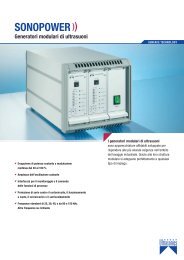
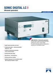
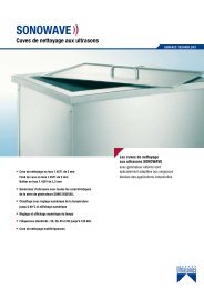
SONIC DIGITAL LC - Ultrasonic generators<strong>Operation</strong>s Manualfor ultrasonic generators from the seriesSONIC DIGITAL LC MDVersion Premium & Basicwww.weber-ultrasonics.comWELDINGArt.Nr: 9000.3101 GB
SONIC DIGITAL LC - Ultrasonic generatorsIntroductionDear Customer,Thank you for purchasing this <strong>Weber</strong> <strong>Ultrasonics</strong> product.You have chosen a first-class product that was developed using the latest technology.www.weber-ultrasonics.comIt is vital that you read these operating instructions and follow them carefully before installingor commissioning your product. Failure to observe these instructions can present a risk to life.Units may be operated by trained personnel only. Failure to comply with this will result in a lossof warranty rights.The device may only be operated and maintained by personnel who have read and understoodthis operating manual and are familiar with the applicable legal regulations for accident preventionand workplace safety.Safety instructionsBefore starting up your device, please read through the following instructions carefully, both for your ownsafety and for the safety of the device.Keep this manual where it can be readily accessed by all systems users.Installation is to be carried out by qualified technical personnel only!The ultrasonic generator is to be operated by properly trained personnel only!Due to the way it operates, additional safety measures must be taken if the device is to be used in areasposing an explosion risk.The electromagnetic compatibility corresponds to the standards and regulations listed in the specifications.All necessary settings were either made in the factory or are described in this handbook.However, should problems occur on start-up, please do not make any prohibited adjustments to the device,as this would endanger your warranty rights. If in doubt, please contact our technical service staff.Please contact our technical service if at all in doubt.Work inside the device may only be carried out to the extent described and, as with the electrical connection,should only be performed by skilled personnel. When performing such work, the ultrasonic generator must becompletely disconnected from the mains (unplug the mains connection).Inputs or outputs that are used for controlling or monitoring purposes should be twisted and shielded.The device must not be in close proximity to electrically charged components or cables.The shielding should be connected to the generator‘s earth on one side of the generator.Attention: All connections for the signal or control lines are galvanically connected to the generator.Always observe any warnings or instructions given on the device itself.The device must always be disconnected from the mains before cleaning or when installing/uninstalling an option.Do not use liquid cleaners or sprays. Only use a damp cloth.
SONIC DIGITAL LC - Ultrasonic generatorsThe platform for the device must be sufficiently stable, as the device being jolted or falling could cause severe damage.Ensure that the power supply specifications given on the device are met.Only those transducers which have the correct frequency, power output and dimensions may be used with this generator.HF cables from the generator to the transducer as well as mains cables to the generator may not be rolled upif they are too long. Instead, they must be shortened to the required length due to the risk of overheating.www.weber-ultrasonics.comWith the exception of the permitted tasks listed in the handbook, you should never attempt to repair or modify the deviceyourself.In the following cases you should disconnect the device from the mains and contact a qualified service engineer:· If the mains cable or plug is damaged· If liquid has penetrated into the device· If the device has fallen over or the housing is damaged· If the device displays noticeably different behaviour than standard operationATTENTION: Repairs and modifications may only be carried out by competent, skilled personnel.
SONIC DIGITAL LC - Ultrasonic generatorsAssemblyNotes on the installation location 6www.weber-ultrasonics.comPower supply 6Connections on the back of the generator 7Assignment of the 15-pole DSUB interface socket 8Interface Description 8
SONIC DIGITAL LC - Ultrasonic generatorsNotes on the installation locationDuring operation the generator will get very hot.If the generator cannot dissipate this heat sufficiently, it will display an error message dueto excess temperature (see also the “OVER TEMPERATURE” error description).www.weber-ultrasonics.comIn addition, ambient temperatures of over 30°C should be avoided.Choose a suitable location that will protect the device from moisture, water, excessive sunlight and heat.ATTENTION:• Choose a location that will prevent steam or any other aggressive vapoursfrom penetrating the device.• Over a period of time, chemically contaminated ambient air can lead tothe device being irreparably damaged.Power supplyThe ultrasonic generator draws its power (230 V / 50 / 60 Hz) via the connection cable.It has an internal main fuse (10 AF).If you need to change the fuses, unscrew the top of the housing.ATTENTION:• For safety reasons, always disconnect the unit from the mains before changing fuses.• Plug racks into earthed sockets only.• Always replace blown fuses with new fuses of the same type.• This should only be performed by qualified, skilled personnel.
SONIC DIGITAL LC - Ultrasonic generatorsConnections on the back of the generatorwww.weber-ultrasonics.comATTENTION:•Only use cables specified by the manufacturer.• Use only shielded transducer connection cables.• Connect the shielding to the PE conductor on the generator side.• Only use cables with sufficient cross-section.• Minimum cross-section: 1.5 mm 2 .
SONIC DIGITAL LC - Ultrasonic generatorsAssignment of the 15-pole DSUB interface socket8 1www.weber-ultrasonics.com15 9PIN No. on DSUB SOCKETInterface X1Signal nameDescription1 +15 VOLT OUT 15 Volt for external use2 POUT Output 0 – 10 Volt = Power output 0 – 100 %3 P-EXT.-IN Input 5 – 10 Volt for power control4 GND Shared reference point = Ground5/9 HF-DA-ERROR Relay root (shared) for “HF-DA” and “ERROR”6 HF-DA Relay output “HF-DA”7 ERROR Relay output “ERROR”8 NC Not assigned! Do not connect!9/5 HF-DA-ERROR Relay root (shared) for “HF-DA” and “ERROR”10 NC Not assigned! Do not connect!11 Nominal Output for nominal value12 FAN-ON Monitoring output = 12 Volt when the fan is running13 FS-24 V Remote control input (with 15 – 24 Volt)14 FS-GND Remote control input (to GND)15 GND Shared reference point = GroundATTENTION:A shielded control cable must always be used for the interface.Interface Description1.) Signal “+15 Volt Out” DSUB PIN 1A voltage of 15 V is available at this output. This voltage can be loaded with max. 100 mA and can,for example, be used to output a voltage for the function “HF-DA” and/or “Error”.This voltage can also be used to switch on the generator on the input “FS-24 V”.2.) Signal “POUT” DSUB PIN 2At this output a voltage proportional to the power output of between 0 and 10 V(= 0 – 100 % power output) is available.Reference point = “GND”.3.) Signal “P-EXT.-IN” DSUB PIN 3By connecting a voltage between 5 V and 10 V, the output of the generator can be set tobetween 50 % and 100 % of its nominal amplitude or power. To activate this function,go to the Settings menu (password 6354) and select the “external voltage” setting under “Pwr.src”.Reference point = “GND”.
SONIC DIGITAL LC - Ultrasonic generators4.) Signal “HF-DA ERROR” DSUB PIN 5/9Shared in/output for the internal relays “HF-DA” and “ERROR” (these PINs are connected internally).5.) Signal “HF-DA” DSUB PIN 6If the ultrasonic generator has been switched on via either of the signals “FS-24 V”, “FS-GND”or with the test button on the front panel and is emitting HF voltage (i.e. there is no malfunction),an internal floating relay contact is closed. (between PIN 6 und PIN 5/9)www.weber-ultrasonics.comThe “root” of this relay contact leads through to a PIN 5/9 (these pins are connected internally)in the DSUB socket. This relay contact can now be queried by an external control system.A voltage connected to Pin 5/9 can, of course, also be switched through (max. 24 VDC / 100 mA).It is useful to query this contact when a timer operation is being carried out and the generator switchesoff automatically when the time is up (normally closed contact default setting). The contact can also beswitched over to reverse polarity in the Settings menu.Standard factory setting: Contact closed when the generator outputs HF voltage.6.) Signal “Error” DSUB PIN 7This is the output of an internal relay (root to PIN 5/9).This relay reports generator malfunctions. This means that if the generator is switched on and,for some reason, the power output does not correspond to the set level, this relay is activated.Factory default settings: Closed in the event of a malfunction. It is possible to change the polarityin the Settings menu under the heading I/O Polarities (“Error detect”).An external voltage connected to “HF-DA-Error” can, of course, also beswitched through here (max. 24 VDC / 100 mA).7.) Signal “FAN-ON” DSUB PIN 12At this output, there is a control voltage (12 Volt) for monitoring the fan function when the internal fan is running.8.) Signal “FS-24 Volt” DSUB PIN 13Switching on the generator (Ultrasound On) by connecting a voltage between 15 – 24 Voltbetween PIN 13 and GND (PIN 4/15).9.) Signal “FS-GND” DSUB PIN 14Switching on the generator (ultrasound ON) with a relay contact or switch by connectingPIN 14 on the DSUB socket to GND (PIN 4 /15).10.) Signal “ Nominal” DSUB PIN 11Open Collector output: high signal if a window function is active and the generatoris operated outside the window set; low signal if a window function is active andthe generator is operated within the window set.11.) Signal “GND” DSUB PIN 4, 15The GND signal is available on multiple pins of the DSUB socket.It is the common reference point for all input and output signals.
SONIC DIGITAL LC - Ultrasonic generators<strong>Operation</strong>Operator elements and display on the front panel 11www.weber-ultrasonics.comOperating and display elements of the external controller 12The LCD display 13Factory default settings in the menu 1710
SONIC DIGITAL LC - Ultrasonic generatorsOperator elements and display on the front panelwww.weber-ultrasonics.comVersion Premium:LED-Sonic:LED-Nominal:LED-Mode:LED-Error:Lights up when the generator emits HF voltageLights up when a window function is active and the generatoris operated outside the window set.Displays selected special functions.In this version the timer function is signalised.Lights up in the event of an errorLED-Power output display10 – 100 %: Displays the power output in 10 % stepsEncoder / Select:Test button:For setting and entering valuesThe generator can be switched on by pressing this button.11
SONIC DIGITAL LC - Ultrasonic generatorswww.weber-ultrasonics.comVersion Basic:LED-Power:LED-HF:LED-Error:Test button:Front socket:Lights up when the device is being supplied with mains voltage correctlyand the power switch is onLights up when the generator emits HF voltage.Lights up in the event of an error.This button is used to turn on the generator for testing purposes.Connection for external control console. Available as an option.Operating and display elements of the external controllerLED-HF:LED-Aux1:LED-Aux2:LED-Error:Lights up when the generator emits HF voltage.Lights up when a window function is active andthe generator is operated outside the window set.Displays selected special functions.In this version the timer function is signalised.Lights up in the event of an error.LED-Power output display10 – 100 %: Displays the power output in 10 % steps.Encoder / Select:Test button:For setting and entering values.The generator can be switched on by pressingthis button.12
SONIC DIGITAL LC - Ultrasonic generatorsThe LCD displayVarious screens and functions are available in the LCD display:1. Start screenOn the top left is the frequency in Hertz, in the centre the amplitude setin percent (adjustable between 50 % and 100 %), and on the right the lastpower output in watts. In the bar graph, the last power output in percentis also shown in diagram form.www.weber-ultrasonics.com2. Starting frequencyThe display shows the starting frequency of the generator, in this exampleof a 40 kHz generator.3. Power output indicator in “Watts”The current power output is displayed. After switching off the device,the maximum power output reached is saved until the next time thedevice is switched on.4. Amplitude settingHere, the “Select” encoder can be used to set the desired power outputto between 50 % and 100 % of the nominal generator amplitude.The desired amplitude is set by pressing and then turning the encoder.Pressing the encoder again applies the selected amplitude.5. P-Window functionHere, the “Select” encoder can be used to set a window.If the power output is shown within this window, there is a low signal atthe Nominal output (DSUB PIN 11) on the interface (see also interface description).If the power output is outside this window, there is a high signal at the Nominaloutput (DSUB PIN 11) on the interface (see also interface description).If the power output is outside the window, the Nominal LED lights up onthe control panel, or the AUX1 LED lights up on the hand-held operating device.The desired window is set by pressing the encoder. The minimum and maximum valuesof the window can be set by turning the encoder.Pressing the encoder again applies the selected values.6. Timer functionA time of up to 10 seconds can be set by pressing the encoder. If the functions is switchedon, the LED Mode lights up on the operating panel, the AUX2 LED lights up on the hand-heldoperating device. This time starts running when the generator is switched on, either via theinterface or the test button. No error message is displayed when the time expires, “Time out”is on the display. When the generator is switched on using the test button and the time expires,the generator switches off and remains in this state until it is switched on again. The end ofthe expired time can be determined via the interface by requesting the “HF-DA” signal.If an “OFF” time is also set, the generator switches on and off continuously.7. T-Window functionHere, the “Select” encoder can be used to set a window. If the operating time is shownwithin this window, there is a low signal at the Nominal output (DSUB PIN 11) onthe interface (see also interface description). If the operating time is shown outsidethis window, there is a high signal at the Nominal output (DSUB PIN 11) on the interface(see also interface description). If the operating time is outside the window,the Nominal LED lights up on the operating panel or the AUX1 LED lights up onthe hand-held operating device.The desired window is set by pressing the encoder. The minimum and maximumvalues of the window can be set by turning the encoder.Pressing the encoder again applies the selected values.13
SONIC DIGITAL LC - Ultrasonic generators8. Power welding functionHere, the “Select” encoder can be used to set a value in watt-seconds.When the power set is reached, the welding procedure ends.Attention: the welding procedure ends after a maximum of 10 seconds,even if the power set has not been reached.9. CounterThis counts how often the welding procedure has been started.This counter can be reset by the operator.www.weber-ultrasonics.com10. Adjusting the starting frequencyHere, the “Select” encoder can be used to adjust the starting frequency.Depending on the generator‘s basic starting frequency, the startingfrequency can be adjusted by approximately 1.2 kHz to 2 kHz.11. Contrast settingThe contrast of the LCD display can be adjusted by pressing and turning the encoder.Pressing the encoder again applies the set value. Set the contrast in such a way thatthe LCD display can be easily read.12. Display backlightThe display‘s backlight can be turned on and off by pressing and turning the encoder.For optimum readability, we recommend turning the backlight on.13. SettingsYou can access the Settings menu by entering the password “6354”.This is also doneby turning the encoder. After selecting the correct number each time, confirm by pressingthe encoder.Functions in the Settings menu1. Adjusting the starting frequencyThe generator has an automatic “frequency tuning”. This means that it fully automaticallysets itself to the resonant frequency of the connected transducer system. The capturerange is 1 kHz. The resonant frequency of the connected system must be known.Generally, a starting frequency which is approximately 500 Hz above the resonant frequencyof the connected system leads to good results. In special cases, however, it can alsobe necessary to set the starting frequency closer to the resonance of the transducer system.Under no circumstances should the starting frequency be set so that it is below the resonantfrequency of the connected transducer system! The starting frequency can be changedby pressing and then turning the encoder.The area which is covered depends on the device type.2. Control AssignmentHere you can set how the generator is to be controlled. Internal Front means controlvia the front control panel, Front & ext. Voltage means that the generator can also beoperated via an external voltage (see pin assignment of the interface) and RS232 meansthat the generator can be controlled via the RS232 interface (available as an option).14
SONIC DIGITAL LC - Ultrasonic generatorsI/O PolaritiesRemote IN:The polarity of the remote control input can be altered by changingthis value.Factory default settings:A closed contact switches the generator on.www.weber-ultrasonics.comSymbol “H”:Symbol “L”:Error out:Symbol “L”:Symbol “H”:When the contact is closed, the generator is switched on.When the contact is open, the generator is switched on.The polarity of the internal error relay can be switched overby altering this value.Factory default settings: :Opened contact is an error, thereby safe of cable break.The polarity of the internal error relay can be switched over byaltering this value.Closed contact is an error.Opened contact is an error.If the polarity is altered in such a way that a closed contact reports an error, you shouldbe aware that the contact is open when there is no mains voltage at the generator orif the generator displays complete failure.Recommendation: Do not change the factory settings so that the errors described abovecan be detected properly.RF detect:Symbol “H”:Symbol “L”:The status signal HF-DA (generator is emitting HF voltage)can be altered by changing this value.Closed contact – generator emits HF voltage.Open contact – generator emits HF voltage.Please note that when the generator is not connected to the mains or there is a completefailure, this contact is open.Recommendation: Do not change the factory settings.15
SONIC DIGITAL LC - Ultrasonic generatorsPre/Post functionHere a maximum time lag of 1,000 ms can be set before welding. Power is only output afterthis time has expired. An afterburst can be set, which means that there is a fixed waitingtime of 100 ms after the actual welding procedure. Power is then output to the transducersystem again for a maximum of 500 ms to remove residue from the transducer system.Example:Delay before weld200 mswww.weber-ultrasonics.comTime after burst150 msEnergy1,000 WsPause set beforeweldingPower set by operatorFixed waitingtimeAfterburst200 ms 1,000 Ws 100 ms 150 msParameter LockThe basic setting for the Parameter Lock is “Off”. If you set Parameter Lock to “On”, allfunctions in the basic menu other than the LCD contrast settings and the backlight aredisabled for the user. They then cannot be changed until Parameter Lock is set back to“Off” in the Settings menu.Operating hours indicatorThis displays the time during which the generator emitted HF.Display format: Days, hours, minutes.Total run time00d 0h 0mDisplay of the serial number and date of productionIn the Info menu item you can view the serial number and date of productionof the generator.SensoricsBy connecting a voltage between 5 V and 10 V to PIN 3 of the interface, the output of thegenerator can be set to between 50 % and 100 % of the nominal amplitude or power.The voltage connected can be displayed in percent here. 10 V corresponds to 100 %,so in this example we can see that the voltage is 6.5 V. To activate this function, go to theSettings menu (password 6354) and select the “external voltage2” setting under “Pwr.src”.65%Reference point = “GND”EXIT – Exiting the Settings menuExit16
SONIC DIGITAL LC - Ultrasonic generatorsFactory default settings in the menuThe framed settings are the basic settingswww.weber-ultrasonics.comDepends on the frequency of the generatorDepends on the frequency of the generatorDepends on the frequency of the generator17
SONIC DIGITAL LC - Ultrasonic generatorsCntrol & Paramsare accepted frominternal frontCntrol & Paramsare accepted fromfront & ext. voltageCntrol & Paramsare accepted fromRS232www.weber-ultrasonics.comP-Limiternot availableParameter Lock(off)Parameter Lock(on)Total run time 00d 0h 0mmodule n/a65%18
SONIC DIGITAL LC - Ultrasonic generatorsError messages and troubleshootingThe following error messages may appear in the display:A – PROTECTION ACTIVEThe electronic overcurrent fuse has detected an errorEA protectionactivewww.weber-ultrasonics.comPossible causes:· Transducer is defective· Power supply or plug is defectiveRemedy:· Unscrew the transducer connection on the housing· Switch on the generator without the transducer connecteda.) Error message still displayed:Generator is defectiveb.) Error message no longer displayed:Check the transducer and power supplyNO RF – DETECTEDThe electronic overload/short-circuit fuse has detected an error.Causes and remedy: see “A-PROTECTION ACTIVE”ENo RFdetected!E-SEARCHThe generator cannot find the working frequencyPossible causes:· No transducer system connected· Transducer system defective· Supply cable or plug connector defectiveESearchRemedy:· Replace transducer system· Check supply cable and plug-in connectionsOVER TEMPERATUREThe generator is too hotPossible causes:· The generator‘s ventilation slits are blocked· Unsuitable location for the generator· The transducer is defective· The fan is defectiveTemperatureE limit reachedRemedy:· Check the fan! When the mains power is switched on,the fan should briefly start running· Check the air flow to and from the generator(The fan should not be assembled upwards)· Check the transducers19
SONIC DIGITAL LC - Ultrasonic generatorsWarrantyThe length and coverage of the warranty can be found in the terms of delivery as part of the general termsand conditions (valid at the time of purchase) or in the sales contract / order confirmation, should anyspecial agreements have been made.The following cases are not covered by warranty:www.weber-ultrasonics.com· Damage caused by inappropriate operation· The device not being used for its intended purpose· Inappropriate alterations or modifications made without prior authorisation fromthe manufacturer· Damage caused by extreme circumstances, such as knocks, falling over, moisture and dirt· Insufficiently qualified operating staff· Non-compliance with current safety and accident-prevention regulations· Damage resulting from modifications made to the operating instructionsDeclaration of CE conformanceWe: <strong>Weber</strong> <strong>Ultrasonics</strong> <strong>GmbH</strong>Im Hinteracker 7D-76307 KarlsbadGermanyhereby declare under our sole responsibility that the product:Designation:Ultrasonic generator “LC xxxx MD”(xxxx is for different power output)Conforms to the requirements of the following EMV standards:EN 50081-1EN 50082-2EN 55022EN 55014EN 60555EN 61000and meets the requirements of the Low Voltage Directive.Karlsbad, 10.11.2004Markus <strong>Weber</strong>Managing Director21
SONIC DIGITAL LC - Ultrasonic generatorsIndexA/BAssemblyAssignment of the interfacesocket 8Assignment of the mainsconnection 6Installation 3, 6F/G/HFuse 6, 20, 21I/J/KInterface 8Introduction 3SSettings 14–16Safety instructions 3Spare partsSpecifications0T/Uwww.weber-ultrasonics.comCCE conformance1Connections 7, 8Connection of the externalcontroller 12LLCD display of theexternal controller 13Location 3, 6Output setting 13Test button 11, 12Timer function 13T-Window 13VContrast setting 14M/N/OVoltage 6, 20DDimension generator 20Display backlight 14Maintenance0<strong>Operation</strong> 10Operating hours 16Operating and display elements 12W/X/Y/ZWarranty1EError messagesand troubleshooting 19Power welding 14Operating and display elementsof the generator 11, 12P/Q/RPolarities 15Power output indicator 13Power supply 6, 20P-Window 13Service hotlineShould you still have questions after reading through the operating instructions thoroughly,please feel free to call our service hotline.Please have the following information to hand to help us answer your questions quickly.Device type, serial number (the serial number is on the backside of the generator)Spare partsOur service hotline number:+49 (0) 72 48 / 92 07-0We can only deliver spare parts and accessories if you quote the serial number of your device.22