CS2 - SMC
CS2 - SMC
CS2 - SMC

Create successful ePaper yourself
Turn your PDF publications into a flip-book with our unique Google optimized e-Paper software.
Air Cylinder Series <strong>CS2</strong><br />
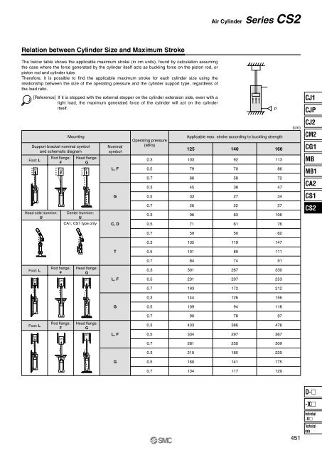
Relation between Cylinder Size and Maximum Stroke<br />
The below table shows the applicable maximum stroke (in cm units), found by calculation assuming<br />
the case where the force generated by the cylinder itself acts as buckling force on the piston rod, or<br />
piston rod and cylinder tube.<br />
Therefore, it is possible to find the applicable maximum stroke for each cylinder size using the<br />
relationship between the size of the operating pressure and the cylinder support type, regardless of<br />
the load ratio.<br />
[Reference] If it is stopped with the external stopper on the cylinder extension side, even with a<br />
light load, the maximum generated force of the cylinder will act on the cylinder<br />
itself.<br />
P<br />
CJ1<br />
CJP<br />
Mounting<br />
Support bracket nominal symbol<br />
and schematic diagram<br />
Foot: L<br />
Rod flange:<br />
F<br />
Head flange:<br />
G<br />
W W W<br />
Nominal<br />
symbol<br />
L, F<br />
Operating pressure<br />
(MPa)<br />
0.3<br />
0.5<br />
0.7<br />
0.3<br />
Applicable max. stroke according to buckling strength<br />
125<br />
140<br />
160<br />
103<br />
92<br />
113<br />
79<br />
70<br />
86<br />
66<br />
58<br />
72<br />
45<br />
38<br />
47<br />
(cm)<br />
CJ2<br />
CM2<br />
CG1<br />
MB<br />
MB1<br />
CA2<br />
G<br />
0.5<br />
33<br />
27<br />
34<br />
CS1<br />
Head side trunnion:<br />
U<br />
Center trunnion:<br />
U<br />
CA1, CS1 type only<br />
C, D<br />
0.7<br />
0.3<br />
0.5<br />
26<br />
96<br />
71<br />
22<br />
83<br />
61<br />
27<br />
106<br />
76<br />
<strong>CS2</strong><br />
W<br />
W<br />
0.7<br />
59<br />
50<br />
62<br />
0.3<br />
135<br />
119<br />
147<br />
T<br />
0.5<br />
101<br />
89<br />
111<br />
0.7<br />
84<br />
74<br />
91<br />
Foot: L<br />
W<br />
Rod flange:<br />
F<br />
W<br />
Head flange:<br />
G<br />
W<br />
L, F<br />
0.3<br />
0.5<br />
301<br />
231<br />
267<br />
207<br />
330<br />
253<br />
0.7<br />
193<br />
172<br />
212<br />
0.3<br />
144<br />
126<br />
156<br />
G<br />
0.5<br />
109<br />
94<br />
118<br />
0.7<br />
90<br />
78<br />
97<br />
Foot: L<br />
W<br />
Rod flange:<br />
F<br />
W<br />
Head flange:<br />
G<br />
W<br />
L, F<br />
0.3<br />
0.5<br />
0.7<br />
433<br />
334<br />
281<br />
386<br />
297<br />
250<br />
476<br />
367<br />
309<br />
0.3<br />
210<br />
185<br />
229<br />
G<br />
0.5<br />
160<br />
141<br />
175<br />
0.7<br />
134<br />
117<br />
129<br />
D-<br />
-X<br />
451<br />
Individual<br />
-X<br />
Technical<br />
data