æ°åé屬天ç·å¾®å¸¶å¹é å¨çè¨è¨èéç¼ - é¸è»è»å®å¸æ ¡
æ°åé屬天ç·å¾®å¸¶å¹é å¨çè¨è¨èéç¼ - é¸è»è»å®å¸æ ¡
æ°åé屬天ç·å¾®å¸¶å¹é å¨çè¨è¨èéç¼ - é¸è»è»å®å¸æ ¡

Create successful ePaper yourself
Turn your PDF publications into a flip-book with our unique Google optimized e-Paper software.
黃 埔 學 報 第 五 十 三 期 民 國 九 十 六 年<br />
WHAMPOA - An Interdisciplinary Journal 53(2007) 111-114<br />
111<br />
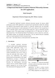
Microstrip Circuitry Impedance Matching Regulator Design for a Simple<br />
Rectangular Metal Radiator in an Antenna<br />
Shen Cherng 1 , Yuan-Tung Cheng 2 , Hsien-Chiao Teng 3<br />
1<br />
Graduate Intitute of Electrical Engineering, Chengshiu University<br />
2<br />
Graduate Intitute of Electronic Engineering, Chengshiu University<br />
3<br />
Department of Electrical Engineering, Chinese Military Academy<br />
Abstract<br />
A microstrip circuit recommended can be used as an impedance matching regulator<br />
for adjusting the VSWR of a loading device. A simple rectangular metal antenna is on the<br />
application of being improved the impedance matching and the antenna gain at specific<br />
operation frequencies. In this article, an equivalent circuit as the result of transmission line<br />
model is proposed.<br />
Key words: SWR , microstrip circuit , equivalent circuit<br />
1. Introduction<br />
Using probing network circuit to<br />
control the function of microstrip antenna<br />
has been discussed a lot [1]. However, the<br />
equivalent circuit created from the<br />
microstrip transmission line model is very<br />
difficult to be constructed due to the<br />
characteristics of the distributed microstrip<br />
elements of the circuit being coupled to the<br />
antenna operated on S band and C band.<br />
The dilemma exists in both Thevenin and<br />
Norton equivalents [2]. We proposed a<br />
circuit with loading device includes two<br />
admittances, one for the load of the<br />
functional microstrip band-pass circuit and<br />
one for the metal radiator [4, 5, 6, 7]. The<br />
microstrip circuit regulates the VSWR to<br />
filter out specific frequency on the bands<br />
and select available operation frequencies.<br />
2. Configuration<br />
Figure 1. shows schematic drawing<br />
of the top view of the proposed microstrip<br />
circuit. The circuit includes three parts<br />
(components), microstrip circuit, connecting<br />
path and a copper metal radiator (metal<br />
antenna). As shown in the figure, the<br />
filter circuit and via path connecting to the<br />
metal radiator can be analyzed by using<br />
transmission line model.<br />
3. Results and Discussion<br />
The proposed antenna is depicted in<br />
Figure 1. The thickness and dielectric<br />
constant of the FR4 plate are indicated d =<br />
0.4 mm, ε<br />
r<br />
= 4.4. Figure 2 depicts the<br />
return loss of the measurement of the<br />
antenna including microstrip strip circuit
112 黃 埔 學 報 第 五 十 三 期 民 國 九 十 六 年<br />
coupled to a major metal radiator as loading<br />
device.<br />
Figure 2. Measurement of the<br />
Return Loss.The impedance<br />
matching of the metal antenna<br />
at 2.85GHz is shown being<br />
improved by coupling to<br />
microstrip circuit regulator<br />
(1)<br />
(A) parameters of the circuit<br />
(B) parameters determined by<br />
neuronet calculation<br />
Figure 1. A microstrip circuit<br />
with loading device.<br />
Figure 3. depicted the prototype of<br />
the design constructed. Figure 4.<br />
demonstrates the field-patterns of the<br />
antenna, including radiator and the<br />
microstrip circuit impedance matching<br />
regulator, that the filter circuit via path being<br />
connected to radiator. The presence of the<br />
forward and backward scattering current<br />
driven by filter circuit delivers the excitation<br />
power via path for the modes of resonances<br />
of the metal radiator. In Figure 5., the gain<br />
of the proposed antenna is depicted. The<br />
filter circuit can improve the impedance<br />
matching and select 2.85 GHz in S band as<br />
well as reducing XPL at elevation plan.<br />
Morover, at other available operating<br />
frequencies, we can observe much better<br />
omnidirectional field pattern and reduced<br />
XPL .(not shown in figure)
Shen Cherng、Yuan Tung Cheng Hsien-Chiao Teng:Microstrip Circuitry Impedance Matching 113<br />
Regulator Design for a Simple Rectangular Metal Radiator in an Antenna<br />
Figure 3. The prototype of the proposed<br />
design constructed<br />
The parameters of the microstrip<br />
lines can be optimized by radial basis<br />
neuronet model. The calculated parameters<br />
are depicted in the following table I.<br />
Figure 5. Gain of the metal antenna<br />
coupling to the proposed microstrip<br />
circuit<br />
Conclusion<br />
Figure 4. The measured radiation<br />
pattern at 2.85GHz<br />
The proposed design of microstrip<br />
filter circuit coupling to metal radiator can<br />
be used to select available frequency-bands<br />
for carrying out specific gain for mobile<br />
system, for instance space shuttle or<br />
WiMAX consideration. Under the<br />
conditions of least XPL, the optional design<br />
of the filter circuit can be performed to<br />
satisfy the specification for the users.<br />
References<br />
Table ( I ) The parameters of the<br />
microstrip lines<br />
unit:mm<br />
(W 1 S 1 ) (W 2 S 2 ) (W 3 S 3 ) (W 4 S 4 ) (W 5 S 5 )<br />
(4,8) (2,1) (6,9) (2,1) (4,8)<br />
[1]. KL Wong, Planar antennas for wireless<br />
communications, Chapter 5~7, John<br />
Wiley & Sons, New York, NY.2003<br />
[2]. JV Bladel, ” On equivalent circuit of a<br />
receiving antenna ,” IEEE Antennas and<br />
Propagation Magazine, vol.44, No.1,<br />
pp164~165, February, 2002<br />
[3]. KL Wong, CH Wu and FS Chang, “A
114 黃 埔 學 報 第 五 十 三 期 民 國 九 十 六 年<br />
compact wideband omnidirectional cross<br />
plate monopole antenna,” Microwave<br />
and Optical Technology Letters, vol.44,<br />
No.6, pp492~494, March 20, 2005<br />
[4]. JP Kim, ”Analysis and equivalent circuit<br />
of aperture-coupled cavity-fed<br />
microstrip patch antenna,” Microwave<br />
and Optical Technology Letters, vol.48,<br />
No.5, pp843~846, May, 2006<br />
[5]. AW Love,” Comment : On equivalent<br />
circuit of a receiving antenna,” IEEE<br />
Antennas and Propagation Magazine,<br />
vol.44, No. 5, pp124~125, October, 2002<br />
[6]. JV Bladel, ” On equivalent circuit of a<br />
receiving antenna ,” IEEE Antennas and<br />
Propagation Magazine, vol.44, No.1,<br />
pp164~165, February, 2002<br />
[7]. TW Chiou and KL Wong, ”Designs of<br />
compact microstrip antennas with a<br />
slotted ground plan,” 2001 IEEE<br />
Antennas Propagat. Soc.Int. Symp. Dig.,<br />
pp732~735<br />
新 型 金 屬 天 線 微 帶 匹 配 器 的 設 計 與 開 發<br />
程 深<br />
1 , 程 遠 東<br />
2 , 鄧 先 巧<br />
3<br />
1<br />
正 修 科 技 大 學 電 機 研 究 所<br />
2<br />
正 修 科 技 大 學 電 子 研 究 所<br />
3<br />
陸 軍 軍 官 學 校 電 機 系<br />
摘 要<br />
利 用 微 帶 線 設 計 濾 波 電 路 , 可 以 用 作 天 線 的 匹 配 器 , 選 擇 想 要 的 操 作 頻 率 與 適 當 的<br />
匹 配 條 件 。 本 篇 論 文 提 出 一 種 簡 單 的 濾 波 電 路 , 可 以 作 為 匹 配 器 , 具 有 良 好 的 選 頻 以<br />
及 調 整 匹 配 SWR 的 功 能 。<br />
關 鍵 字 : SWR, 微 帶 電 路 , 等 效 電 路