Kromschroder MODULINE Brochure - Combustion 911
Kromschroder MODULINE Brochure - Combustion 911
Kromschroder MODULINE Brochure - Combustion 911

Create successful ePaper yourself
Turn your PDF publications into a flip-book with our unique Google optimized e-Paper software.
–<br />
–<br />
–<br />
–<br />
–<br />
–<br />
Filter<br />
+<br />
Pressure<br />
monitoring<br />
+<br />
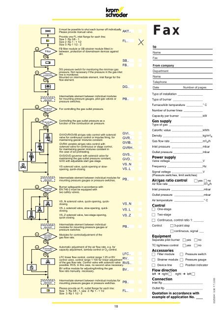
It must be possible to shut each burner off individually<br />
Please provide manual valve.<br />
Provide one FL inlet flange for each line:<br />
Size 1: Rp 3/8 - 1<br />
Size 2: Rp 1 - 1 1/2<br />
Size 3: Rp 1 1/2 - 2<br />
FB filter module or SB strainer module fitted inbetween,<br />
protection of downstream devices against<br />
dirt.<br />
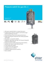
DG pressure switch for monitoring the min/max gas<br />
pressure. Not necessary if the pressure in the gas inlet<br />
line is monitored.<br />
Mounted on intermediate element, inlet flange for the<br />
flow element.<br />
AKT..<br />
FL..<br />
SB..<br />
FB..<br />
DG..<br />
A<br />
F<br />
S<br />
F<br />
D<br />
Fax<br />
to<br />
Name<br />
Fax<br />
From company<br />
Department<br />
Name<br />
Telephone<br />
Date<br />
Number of pages<br />
–<br />
Intermediate<br />
element<br />
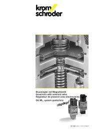
Governor<br />
system<br />
+<br />
Pneumatic<br />
link<br />
+<br />
Intermediate<br />
element<br />
Second<br />
valve<br />
+<br />
Intermediate element between individual modules<br />
for mounting pressure gauges, pilot gas valves or<br />
pressure switches.<br />
For controlling the gas outlet pressure.<br />
Controlling the gas outlet pressure as a<br />
function of the combustion air pressure.<br />
GVI/GVR/GVIB air/gas ratio control with solenoid<br />
valve for continuous control or impulse firing, for<br />
maintaining gas/air mixtures constant.<br />
GVRH variable air/gas ratio control with<br />
solenoid valve for continuous or stage control,<br />
for maintaining gas/air mixtures constant in<br />
the case of air-preheating.<br />
GVS/GVD governor with solenoid valve for<br />
maintaining the gas outlet pressure constant,<br />
GVD with adjustable start gas stage.<br />
VS solenoid valve, quick-opening or slowopening,<br />
quick-closing.<br />
Intermediate element between individual modules for<br />
mounting pressure gauges or pressure switches.<br />
Burner safeguards in accordance with<br />
EN 746-2 must be equipped with<br />
two safety valves.<br />
PB..<br />
GVI..<br />
GVR..<br />
GVIB..<br />
GVRH..<br />
GVS..<br />
GVD..<br />
VS..N<br />
VS..L<br />
PB..<br />
P<br />
G<br />
G<br />
G<br />
G<br />
G<br />
G<br />
V<br />
V<br />
P<br />
Type of installation _________________<br />
Type of burner ____________________<br />
Furnace/kiln temperature ___________° C<br />
Number of burner lines _____________<br />
Capacity per burner _______________kW<br />
Gas supply<br />
Type of gas _______________________<br />
Calorific value _____________________kW/h<br />
Density ___________________________kg/m 3 N<br />
Gas flow rate ______________________m 3 N/h<br />
Inlet pressure _____________________mbar<br />
Outlet pressure ____________________mbar<br />
Power supply<br />
Valve voltage ______________________V<br />
Frequency ________________________Hz<br />
Signal voltage _____________________V<br />
(Pressure switches, limit switches)<br />
Air/gas ratio control yes no<br />
Air flow rate ________________________m 3 N/h<br />
Inlet pressure ______________________mbar<br />
Outlet pressure ____________________mbar<br />
Intermediate<br />
element<br />
Adjusting<br />
quantity<br />
of gas<br />
+<br />
Automatic<br />
control<br />
+<br />
M<br />
Intermediate<br />
element<br />
VS..N solenoid valve, quick-opening, quickclosing.<br />
VS..L solenoid valve, slow-opening, quickclosing.<br />
VS..Z solenoid valve, two-stage-opening,<br />
quick-closing.<br />
Intermediate element between individual<br />
modules for mounting pressure gauges or<br />
pressure switches.<br />
Modules for control/adjustment of the<br />
gas flow rate.<br />
Automatic adjustment of the air flow rate, e.g. for<br />
capacity adjustment, lambda control or O 2 control.<br />
LFC..<br />
LFC linear flow control, control range 1:25 or RV<br />
control valve, control range 1:100 for linear adjustment RV..<br />
of the gas flow rate. Control valve with solenoid valve RVS..<br />
possible: RVS. In this case, no second valve necessary.<br />
BV orifice module for adjusting/limiting the gas BV..<br />
flow rate manually. necessary.<br />
Intermediate element between individual modules for<br />
mounting pressure gauges or pressure switches.<br />
Please provide an FL outlet flange for each line:<br />
Size 1: Rp 3/8 - 1, size 2: Rp 1 - 1 1/2<br />
Size 3: Rp 1 1/2 - 2<br />
VS..N<br />
VS..L<br />
VS..Z<br />
PB..<br />
PB..<br />
FL..<br />
V<br />
V<br />
V<br />
P<br />
L<br />
R<br />
R<br />
B<br />
P<br />
F<br />
Air temperature ____________________° C<br />
Control<br />
One-stage<br />
Two-stage<br />
Continuous, control ratio 1: _______<br />
Control: 3-point step<br />
continuous, signal ___<br />
Equipment<br />
Separate pilot burner yes no<br />
TC tightness control yes no<br />
Accessories<br />
Filter module Pressure switch<br />
Strainer module Pressure gauge<br />
Device line Position indicator<br />
Flow direction<br />
left ➔ right right ➔ left <br />
Connection<br />
Inlet Rp ___________________________<br />
Outlet Rp _________________________<br />
Quotation in accordance with<br />
example of application No. ____<br />
03250041 9.98 F.T 2.000<br />
18