Kromschroder MODULINE Brochure - Combustion 911
Kromschroder MODULINE Brochure - Combustion 911
Kromschroder MODULINE Brochure - Combustion 911

Create successful ePaper yourself
Turn your PDF publications into a flip-book with our unique Google optimized e-Paper software.
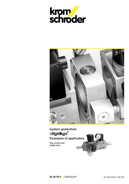
system gastechnic<br />
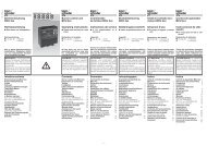
Examples of application<br />
Gas control and<br />
safety lines<br />
5.1.3.2 Edition 5.95 GB
system gastechnic<br />
Mini gas control line with maxi<br />
capabilities<br />
Gas is used as an environment-friendly<br />
source of energy in industry to produce<br />
and process aluminium, steel, ceramics,<br />
glass and foodstuffs. For decades now,<br />
Kromschröder has been constructing gas<br />
control and safety lines in order to use this<br />
gas safely.<br />
10<br />
8<br />
9<br />
12<br />
4<br />
5<br />
11<br />
13<br />
14<br />
3<br />
2<br />
2<br />
6<br />
Air<br />
7<br />
Gas<br />
1<br />
15<br />
11.Gas inlet line<br />
12.Flow rate metering<br />
13.Burner line,<br />
gas-end<br />
14.Burner line, air-end<br />
15.Burner<br />
16.Ignition and flame<br />
failure control<br />
17.Air inlet line<br />
18.Temperature<br />
measurement<br />
19.Furnace pressure<br />
governor system<br />
10.Flue gas analysis<br />
11.Air pressure governor<br />
system<br />
12.Hot air compensation<br />
13.Recuperative safety<br />
governor system<br />
14.Air/gas ratio control<br />
15.Regulation and control<br />
system<br />
2
1<br />
, 0<br />
.0<br />
8<br />
2<br />
. 0<br />
.0<br />
7<br />
. 0<br />
6<br />
5 .0<br />
1<br />
2<br />
. 0<br />
7<br />
. 0<br />
6<br />
5 .0<br />
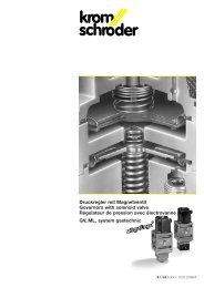
as a modular system<br />
Compact overall dimensions<br />
Easy operation<br />
Many combination options<br />
Easy interchangeability<br />
Easy expandability<br />
Value-for-money<br />
Compact system from one single<br />
source<br />
FL..E +<br />
VS..N +<br />
FL..A<br />
FL..E +<br />
VS..N +<br />
VS..L +<br />
FL..A<br />
,<br />
,<br />
FL..E +<br />
FB +<br />
GVS +<br />
VS..N +<br />
FL..A<br />
,<br />
,<br />
,<br />
9 .0<br />
1 0 .0<br />
, 0<br />
8 .0<br />
.0<br />
3 .0<br />
4 .0<br />
FL..E +<br />
FB +<br />
GVS+DG +<br />
BV+ Pressure gauge +<br />
VS..N +<br />
FL..A<br />
,<br />
,<br />
,<br />
9 .0<br />
1 0 .0<br />
3 .0<br />
4 .0<br />
FL..E +<br />
FB +<br />
GVS + DG +<br />
BV + Pressure gauge+<br />
VS..N +<br />
LFC +<br />
FL..A<br />
3
The modules<br />
The <strong>MODULINE</strong> system is a complete<br />
product line. It permits compact and<br />
customised gas lines to be configured. It<br />
can be used in all sectors of industrial and<br />
commercial heat generation. Each of the<br />
modules below is EC type tested and certified.<br />
Caption<br />
Inlet pressure 01 = 100 mbar<br />
02 = 200 mbar<br />
03 = 300 mbar<br />
05 = 500 mbar<br />
10 = 1000 mbar<br />
Control ratio F4 = set, 4:1<br />
A = can be set<br />
Mains voltage T = 220/240 V AC<br />
M = 110/120 V AC<br />
K = 24 V DC<br />
P = 24 V AC<br />
Connection 3 = with terminals<br />
6 = with standard plug<br />
Acting time 07 = 7,5 s<br />
15 = 15 s<br />
30 = 30 s<br />
60 = 60 s<br />
Position indicator S = position indicator<br />
G = with gold contacts<br />
Without nonferrous<br />
metals M = without non-ferrous<br />
metals<br />
Valve disk V = Viton<br />
Control E = constant signal<br />
●<br />
<br />
−<br />
= standard<br />
= option<br />
= unavailable<br />
Solenoid valve VS<br />
for safeguarding and controlling the gas<br />
supply to gas burners and gas devices.<br />
The valve is quick-opening (VS..N) or<br />
slow-opening (VS..L). This permits gas<br />
burners to start damped or undamped.<br />
02 T M K 3 6 S G M V V’, ∆p=5 mbar<br />
[m 3 /h]<br />
VS 115..N 11<br />
VS 115..L - - 11<br />
VS 125..N 25<br />
VS 125..L - - 25<br />
VS 232..N 45<br />
VS 232..L - - 45<br />
VS 240..N - 65<br />
VS 240..L - - - 65<br />
VS 350..N - 118<br />
VS 350..L - - - 118<br />
Two-step solenoid valve VS..Z<br />
for safeguarding and controlling the gas<br />
supply to gas burners and gas devices.<br />
The valve opens in two stages. The burner<br />
capacity can thus be selected in two<br />
stages.<br />
02 T M K 3 6 S* G* M V V’, ∆p=5 mbar<br />
[m 3 /h]<br />
VS 115..ZN 18<br />
VS 115..ZL - - 18<br />
VS 125..ZN 27<br />
VS 125..ZL - - 27<br />
VS 232..ZN 45<br />
VS 232..ZL - - 45<br />
VS 350..ZN - 125<br />
VS 350..ZL - - - 125<br />
* Position indicator only for stage 2<br />
Governor<br />
with solenoid valve GVS<br />
for safeguarding and governing the gas<br />
pressure in gas inlet and burner lines. The<br />
set outlet pressure is maintained constant<br />
after opening the solenoid valve.<br />
02 T M K 3 6 S G V’, ∆p=10 mbar<br />
[m 3 /h]<br />
GVS 115 21<br />
GVS 125 30<br />
GVS 232 78<br />
Governor<br />
with solenoid valve GVD<br />
Function as on GVS. Fields of application<br />
relate only to burner lines. The outlet pressure<br />
increases in two stages to the set<br />
value. Gas burners start damped in this<br />
way.<br />
Air/gas ratio control<br />
with solenoid valve GVI<br />
for safeguarding and continuous control<br />
in burner lines. The gas outlet pressure is<br />
controlled after the solenoid valve opens.<br />
The gas outlet pressure follows the varying<br />
air control pressure. The ratio<br />
between gas flow rate and air flow rate<br />
remains constant (1:1).<br />
01 T M K 3 6 S G V’, ∆p=10 mbar<br />
[m 3 /h]<br />
GVD 115 21<br />
GVD 125 30<br />
GVD 232 78<br />
02 T M K 3 6 S G V’, ∆p=10 mbar<br />
[m 3 /h]<br />
GVI 115 21<br />
GVI 125 30<br />
GVI 232 78<br />
4
Air/gas ratio control<br />
with solenoid valve GVIB<br />
Function as for GVI. The GVIB is used for<br />
High/Low/Off control.<br />
02 T M K 3 6 S G V’, ∆p=10 mbar<br />
[m 3 /h]<br />
GVIB 115 21<br />
GVIB 125 30<br />
GVIB 232 78<br />
Variable air/gas ratio control<br />
with solenoid valve GVR<br />
Function as for GVI. The ratio between<br />
gas pressure and air pressure can be set<br />
in order to achieve a high gas outlet pressure<br />
with a low air pressure.<br />
01 F4 A T M K 3 6 S G V’,∆p=10 mbar<br />
[m 3 /h]<br />
GVR 115 - 21<br />
GVR 125 - 30<br />
GVR 232 - 78<br />
Variable air/gas ratio control<br />
with solenoid valve GVRH<br />
for safeguarding and stabilising the<br />
gas/air ratio in installations with airpreheating.<br />
Heating the combustion air<br />
reduces the air flow rate. After the solenoid<br />
valve opens, the GVRH adjusts the<br />
gas flow rate to the air flow rate so as to<br />
maintain a constant ratio.<br />
01 F4 A T M K 3 6 S G V’,∆p=10 mbar<br />
[m 3 /h]<br />
GVRH 115 - 21<br />
GVRH 125 - 30<br />
GVRH 232 - 78<br />
Linear flow control<br />
and RV control valve LFC<br />
for controlling continuously governed<br />
combustion processes. The unit sets the<br />
burner capacity exactly. It is controlled by<br />
a 3-point step control or by a constant signal<br />
(e.g. 4 - 20 mA). Ratio between input<br />
signal and flow rate is linear. Control<br />
range LFC: 25:1, RV: 100:1.<br />
Control valve<br />
with solenoid valve RVS<br />
Function as on RV, with additional solenoid<br />
valve for safeguarding the gas supply.<br />
05 T M P 07 15 30 60 M G E V’,∆p=5 mbar<br />
[m 3 /h]<br />
LFC 108 2,4...6<br />
LFC 115 9...17<br />
LFC 120 20...35<br />
LFC 232 48...67<br />
02 03 05 10 T M P 60 M V G E V’,∆p=5 mbar<br />
[m 3 /h]<br />
RV(S)..232/W - - - 2<br />
RV(S)..232/X - - - 3,3<br />
RV(S)..232/Y - - - 5<br />
RV(S)..232/Z - - - 8<br />
RV(S)..232/A - - - 11<br />
RV(S)..232/B - - - 14,5<br />
RV(S)..232/C - - - 19,3<br />
RV(S)..232/D - - - 29<br />
RV(S)..232/E - - - 43<br />
Accessories<br />
FL connection flanges<br />
SB and FB strainer and filter modules<br />
BV orifice module<br />
PB intermediate element<br />
DG pressure switch<br />
KP 63 pressure gauge<br />
Manual cock for pressure gauge<br />
Attachment bracket<br />
Connecting set<br />
These accessories permit combinations<br />
to be configured easily and quickly, from<br />
the single device through to the complex<br />
gas control and safety line.<br />
General technical data<br />
Type of gas: natural gas, town gas, liquefied<br />
petroleum gas (LPG); biologically<br />
produced methane as a special version<br />
Fitting position: vertical or horizontal<br />
V’, ∆p=5 mbar<br />
∆p max = 10 mbar<br />
[m 3 /h]<br />
FB 1 24<br />
FB 2 76<br />
FB 3 109<br />
V’, ∆p=5 mbar<br />
SB 1 79<br />
SB 2 173<br />
SB 3 267<br />
BV 1 95<br />
BV 2 286<br />
BV 3 405<br />
All flow rates apply to natural gas.<br />
5
Overview of the most popular furnace/kiln<br />
installation and processes in<br />
the various industrial plants<br />
The table below lists examples of application<br />
in the last column for each type of furnace<br />
or kiln. These examples relate to the<br />
burner line and air/gas ratio control. They<br />
are explained in further detail on the pages<br />
which follow.<br />
Abbreviation General designation Abbreviation General designation<br />
NM Nozzle-mixing burner Man. Bu. Manual burner<br />
PM Pre-mixing burner Imp. Impulse burner<br />
Atm. Bu. Atmospheric burner Module Continuous control<br />
Inj. Bu. Injection burner A/Z Stages, On/Off<br />
Inj. Gas Gas injection A/K/Z Stages, High/Low/Off<br />
Recu Recuperative burner Direct Incorporated ignition<br />
Recu-Rt Recuperative radiant tube burner device<br />
Rt Radiant tube burner Pilot Separate pilot<br />
Regener Regenerative burner burner<br />
Branches of<br />
industry<br />
Iron and steel,<br />
component<br />
supply<br />
industry<br />
(sheet metal)<br />
Non-ferrous<br />
metals,<br />
aluminium<br />
Heavy-clay<br />
and fine<br />
ceramics<br />
Glass<br />
Cement, thermal<br />
afterburning<br />
and<br />
waste etc.<br />
Packaging,<br />
paper, paint,<br />
films<br />
Rubber<br />
Chemicals,<br />
refineries<br />
Foodstuffs<br />
Soldering and<br />
brazing plants<br />
Installation Type of Heating Shape P Lambda Control Type of Process Air Ignition Example<br />
burner method of flame range operation temperature temperature of appl.<br />
[kW] [m 3 G/m 3 L] [˚C] [˚C]<br />
Cupola furnaces NM Direct Short 500-2000 ~1.05 1:15 Module 1350 20-200 Direct Pilot 5<br />
Crucibles NM Direct Soft 150-1500 p 1.05 1:10 Module A/Z 1350 Direct Pilot 1,2,3,5<br />
Holding burners NM Direct Soft 150-1500 ... 1.0 1:10 Module 1350 Direct 5<br />
Manual burners PM Direct Soft 150-1100 p 1-2 1:12 Module 1350 1,2,3<br />
Forging furnaces NM Direct Short 100-1300 p 1.05 1:20 Module 1150 450 Direct Pilot 1,3,5,7<br />
Recu Direct Short 111-1200 p 1.05 A/Z 1150 pilot 3,8<br />
Regener Direct Short ~500 p 1.05 A/Z 1150 Direct 1<br />
NM Direct Flat ~500 p 1.05 1:1.5 A/Z 1150 Direct 1,7<br />
NM Direct Short 100-1300 p 1.05 1:20 A/K/Z 1150 Direct 7<br />
Heat treatment NM Direct Long 100-1300 ... 1.05 1:10 A/K/Z
Example of application 1<br />
For safeguarding and controlling atmospheric<br />
burners, e.g. excess gas burners,<br />
flame curtains and one-stage burners, in<br />
addition to preheating burners.<br />
One-stage control of<br />
atmospheric burners<br />
Mode of operation: After checking the<br />
gas pressure, the automatic burner control<br />
unit opens the two solenoid valves for<br />
gas. The governor ensures a constant<br />
outlet pressure.<br />
Governor version GVD reaches the set<br />
gas outlet pressure in two stages<br />
(damped).<br />
1 2 3<br />
4<br />
5<br />
6<br />
7 8<br />
1 AKT manual valve<br />
2 FL inlet flange<br />
3 SB strainer module or<br />
FB filter module<br />
4 DG pressure switch<br />
5 Solenoid valve and GVS<br />
or GVD governor<br />
6 PB intermediate element<br />
with manual cock and<br />
pressure gauge<br />
7 VS solenoid valve<br />
8 FL outlet flange<br />
7
Example of application 2<br />
For safeguarding and controlling twostage<br />
atmospheric burners such as heating<br />
burners.<br />
Two-stage control of<br />
atmospheric burners<br />
Mode of operation: After checking the<br />
gas pressure, the automatic burner control<br />
unit opens the first valve and the first<br />
stage of the second solenoid valve for<br />
gas. The governor ensures a constant outlet<br />
pressure. After the flame is produced,<br />
the second stage of the second solenoid<br />
valve for gas is opened when heat<br />
demand occurs, e.g. signalled by a temperature<br />
control.<br />
1 2 3<br />
4<br />
5<br />
6<br />
7 8<br />
1 AKT manual valve<br />
2 FL inlet flange<br />
3 SB strainer module or<br />
FB filter module<br />
4 DG pressure switch<br />
5 GVS governor with<br />
solenoid valve<br />
6 PB intermediate element<br />
with manual cock and<br />
pressure gauge<br />
7 VS..ZL two-step solenoid<br />
valve<br />
8 FL outlet flange<br />
8
Example of application 3<br />
For safeguarding and controlling onestage<br />
atmospheric burners with pilot<br />
burner.<br />
One-stage control of monitored<br />
atmospheric burners with pilot<br />
burner<br />
Mode of operation: After checking the<br />
gas pressure, the automatic burner control<br />
unit opens the first solenoid valve for<br />
gas and the pilot solenoid valve for gas.<br />
The governor ensures a constant outlet<br />
pressure. After the flame is produced, the<br />
second solenoid valve for gas is opened<br />
on demand, e.g. signalled by a temperature<br />
control.<br />
1 2 3<br />
4<br />
5<br />
6<br />
9<br />
7<br />
8<br />
1 AKT manual valve<br />
2 FL inlet flange<br />
3 SB strainer module or<br />
FB filter module<br />
4 DG pressure switch<br />
5 GVS governor with solenoid<br />
valve<br />
6 PB intermediate element<br />
with manual cock and<br />
pressure gauge<br />
7 VS solenoid valve<br />
8 FL outlet flange<br />
9 MVB 4 or VG pilot<br />
solenoid valve for gas<br />
9
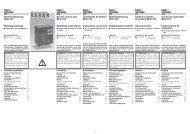
Example of application 4<br />
For safeguarding and controlling process<br />
burners, such as afterburning installations,<br />
drying plants and furnace/kiln installations<br />
for the ceramics industry, in addition<br />
to one-stage burners and gas engines<br />
with an option for lambda adjustment.<br />
Continuous control<br />
of process burners<br />
Mode of operation: After checking the<br />
gas pressure, the automatic burner control<br />
unit opens both solenoid valves for<br />
gas. The governor ensures a constant<br />
outlet pressure. The control valve for gas<br />
permits the amount of gas to be adjusted<br />
steplessly if using the LFC linear flow control<br />
(25:1) or the RV control valve (100:1).<br />
The combined control valve can be used<br />
with the RVS solenoid valve instead of a<br />
single VS solenoid valve and RV control<br />
valve.<br />
1 2 3<br />
1 AKT manual valve<br />
2 FL inlet flange<br />
3 SB strainer module or<br />
FB filter module<br />
4 DG pressure switch<br />
5 GVS governor with<br />
solenoid valve<br />
6 PB intermediate element<br />
with manual cock<br />
and pressure gauge<br />
7 VS..N solenoid valve<br />
8 LFC linear flow control<br />
or RV control valve<br />
7/8 RVS control valve with<br />
solenoid valve<br />
9 FL outlet flange<br />
4<br />
5<br />
6<br />
M<br />
7 8 9<br />
10
Example of application 5<br />
For safeguarding and controlling steplessly<br />
controlled burners with pneumatic<br />
link between gas and air.<br />
Continuous control<br />
of process burners<br />
with pneumatic link<br />
Mode of operation: After checking the<br />
gas and air pressure and after completion<br />
of the purging process, the butterfly valve<br />
for air moves to ignition position. The<br />
automatic burner control unit opens the<br />
two solenoid valves for gas. A proportional<br />
outlet pressure is produced on the<br />
air/gas ratio control via the impulse line so<br />
that the correct quantity of pilot gas<br />
reaches the burner. When heat demand<br />
occurs, the butterfly valve for air opens<br />
steplessly. This causes the control pressure<br />
to increase and act via the impulse<br />
line on the air/gas ratio control which<br />
results in a higher gas outlet pressure.<br />
This maintains the ratio between amount<br />
of gas and amount of air constant at all<br />
operating points. Use of a motor-actuated<br />
adjuster downstream of the second solenoid<br />
valve for gas permits lambda adjustment.<br />
1 2 3<br />
10<br />
11 AKT manual valve<br />
12 FL inlet flange<br />
13 SB strainer module or<br />
FB filter module<br />
14 DG pressure switch<br />
15 GVI air/gas ratio control<br />
with solenoid valve<br />
16 PB intermediate element<br />
with manual cock and<br />
pressure gauge<br />
17 VS..L solenoid valve<br />
18 BV orifice module<br />
or<br />
LFC linear flow control<br />
19 FL outlet flange<br />
10 DG pressure switch<br />
11 DK ring butterfly valve<br />
with GT 31 gear motor<br />
12 DK adjustment valve<br />
4<br />
M<br />
5<br />
6<br />
11 12<br />
7 8 9<br />
11
Example of application 6<br />
For safeguarding and controlling steplessly<br />
controlled burners with pneumatic<br />
link between gas and air. Adjustable<br />
transmission ratio for controlling a high<br />
gas outlet pressure with low air pressure.<br />
Continuous control<br />
of process burners with<br />
pneumatic link and adjustable<br />
transmission ratio<br />
Mode of operation: After checking the<br />
gas and air pressure and after completion<br />
of the purging process, the butterfly valve<br />
for air moves to ignition position. The<br />
automatic burner control unit opens the<br />
two solenoid valves for gas. A proportional<br />
outlet pressure is produced on the<br />
variable air/gas ratio control via the impulse<br />
line so that the correct quantity of<br />
pilot gas reaches the burner. When heat<br />
demand occurs, the butterfly valve for air<br />
opens steplessly. This causes the control<br />
pressure to increase and act via the<br />
impulse line onto the variable air/gas ratio<br />
control which results in a higher gas outlet<br />
pressure depending on set transmission<br />
ratio. This maintains the ratio between the<br />
quantity of gas and air constant at all<br />
operating points. The combustion chamber<br />
pressure can be fed back to the control<br />
and used to correct the quantity of<br />
gas. Use of a motor-actuated adjuster<br />
downstream of the second solenoid valve<br />
for gas permits lambda adjustment.<br />
1 2 3<br />
10<br />
11 AKT manual valve<br />
12 FL inlet flange<br />
13 SB strainer module or<br />
FB filter module<br />
14 DG pressure switch<br />
15 GVR variable air/gas<br />
ratio control with<br />
solenoid valve<br />
16 PB intermediate element<br />
with manual cock and<br />
pressure gauge<br />
17 VS..L solenoid valve<br />
18 BV orifice module or<br />
LFC linear flow control<br />
19 FL outlet flange<br />
10 DG pressure switch<br />
11 DK ring butterfly valve<br />
with GT 31 gear motor<br />
12 DK adjustment valve<br />
4<br />
M<br />
5<br />
p F<br />
6<br />
11 12<br />
7 8 9<br />
12
Example of application 7<br />
For safeguarding and controlling impulse-controlled<br />
industrial burners with<br />
pneumatic link between gas and air.<br />
Stage control of process<br />
burners with pneumatic link<br />
(impulse firing)<br />
Mode of operation: After checking the<br />
gas and air pressure and after completion<br />
of the purging process, the automatic<br />
burner control unit opens the solenoid<br />
valves for gas. The air valve is closed. The<br />
minimum quantity of air reaches the burner<br />
via a bypass. Likewise, the minimum<br />
quantity of gas is supplied to the burner<br />
by a bypass on the air/gas ratio control.<br />
When heat demand occurs, the air valve<br />
is opened via an impulse control. The<br />
increasing air pressure at the air/gas ratio<br />
control causes a proportional gas outlet<br />
pressure via the impulse line. The burner<br />
is then in high-load state. Use of a motoractuated<br />
adjuster downstream of the<br />
second solenoid valve for gas permits<br />
lambda adjustment.<br />
11 AKT manual valve<br />
12 FL inlet flange<br />
13 SB strainer module or<br />
FB filter module<br />
14 DG pressure switch<br />
15 GVIB air/gas ratio control<br />
with solenoid valve<br />
16 PB intermediate element<br />
with manual cock and<br />
pressure gauge<br />
17 VS..L solenoid valve<br />
18 BV orifice module<br />
or<br />
LFC linear flow control<br />
19 FL outlet flange<br />
10 DG pressure switch<br />
11 MK..R solenoid butterfly<br />
valve<br />
12 DK adjustment valve<br />
1 2 3<br />
10<br />
4<br />
5<br />
6<br />
11 12<br />
7 8 9<br />
13
Example of application 8<br />
For safeguarding and controlling steplessly<br />
and stage-controlled burners with<br />
pneumatic link between gas and air, e.g.<br />
recuperative burners.<br />
Continuous control<br />
of hot-air burners with<br />
pneumatic link<br />
Mode of operation: After checking the<br />
gas and air pressure and after completion<br />
of the purging process, the butterfly valve<br />
for air moves to ignition position. The<br />
automatic burner control unit opens the<br />
two solenoid valves for gas. A proportional<br />
gas outlet pressure is produced at the<br />
variable air/gas ratio control as the result<br />
of the differential pressure at the air orifice<br />
so that the quantity of pilot gas reaches<br />
the burner. When heat demand occurs,<br />
the butterfly valve for air opens. This<br />
causes a higher differential pressure to<br />
act on the variable air/gas ratio control<br />
which results in a higher gas outlet pressure.<br />
When the combustion air is heated<br />
in the recuperative burner, the air flow<br />
rate is reduced and, thus, so too is the<br />
differential pressure of the air orifice. The<br />
gas outlet pressure is reduced accordingly.<br />
If the second pulse connection at<br />
the gas end is used, the gas flow rate is<br />
controlled proportionally to the air flow<br />
rate. This guarantees the same ratio<br />
between gas and air under all operating<br />
states.<br />
11 AKT manual valve<br />
12 FL inlet flange<br />
13 SB strainer module or<br />
FB filter module<br />
14 DG pressure switch<br />
15 GVRH variable air/gas<br />
ratio control with<br />
solenoid valve<br />
16 PB intermediate element<br />
with manual cock and<br />
pressure gauge<br />
17 VS..L solenoid valve<br />
18 BV orifice module<br />
19 FL outlet flange<br />
10 DG pressure switch<br />
11 Orifice plate<br />
12 DK ring butterfly valve<br />
with GT 31 gear motor<br />
13 DK adjustment valve<br />
1 2 3<br />
4<br />
10 M<br />
11<br />
5<br />
6 7 8 9<br />
12 13<br />
14
Example of application 9<br />
For safeguarding and controlling continuously<br />
controlled burners with electronic<br />
link.<br />
Continuous control<br />
of process burners<br />
with electronic link<br />
Mode of operation: After checking the<br />
gas and air pressure and after completion<br />
of the purging process, the ring butterfly<br />
valve and the gas control valve move to<br />
ignition position. The automatic burner<br />
control unit opens the solenoid valves for<br />
gas. The gas pressure is maintained constant<br />
by the gas governor. When there is<br />
a demand for capacity, the gas control<br />
valve and the ring butterfly valve are<br />
opened.<br />
Internal feedback determines the correct<br />
position.<br />
Fail-safe measurement for monitoring the<br />
quantity of gas and quantity of air with<br />
suitable measuring instruments is required.<br />
Independent control of the two media<br />
permits lambda adjustment or correction<br />
in the case of preheated combustion air.<br />
1 2 3<br />
11 AKT manual valve<br />
12 FL inlet flange<br />
13 SB strainer module or<br />
FB filter module<br />
14 DG pressure switch<br />
15 GVS governor with<br />
solenoid valve<br />
16 PB intermediate element<br />
with manual cock and<br />
pressure gauge<br />
17 VS..N solenoid valve<br />
18 LFC linear flow control or<br />
RV control valve<br />
19 FL outlet flange<br />
10 DG pressure switch<br />
11 DK ring butterfly valve<br />
with GT 31 gear motor<br />
10<br />
4<br />
5<br />
6 4-20mA<br />
M<br />
7 8 9<br />
M 4-20mA<br />
11<br />
15
Example of application 10<br />
For safeguarding and controlling steplessly<br />
controlled burners with mechanical<br />
link between gas and air, with broad control<br />
range.<br />
Continuous control<br />
of process burners with<br />
mechanical link<br />
Mode of operation: After checking the<br />
gas and air pressure and after completion<br />
of the purging process, the gas control<br />
valve moves to ignition position. The<br />
mechanical link means that the butterfly<br />
valve is also in ignition position. The automatic<br />
burner control unit opens the two<br />
solenoid valves for gas so that the quantity<br />
of pilot gas reaches the burner.<br />
When heat demand occurs, the gas control<br />
valve opens steplessly. The butterfly<br />
valve for air is opened via a cam disk. The<br />
ratio between gas flow rate and air flow<br />
rate can be set by means of the cam disk.<br />
11 AKT manual valve<br />
12 FL inlet flange<br />
13 SB strainer module or<br />
FB filter module<br />
14 DG pressure switch<br />
15 GVS governor with<br />
solenoid valve<br />
16 PB intermediate element<br />
with manual cock and<br />
pressure gauge<br />
17 RVS control valve with<br />
solenoid valve<br />
18 LKS 3 cam disk<br />
19 FL outlet flange<br />
10 DG pressure switch<br />
11 DK ring butterfly valve<br />
12 DK adjustment valve<br />
1 2 3<br />
10<br />
4<br />
5<br />
6<br />
M<br />
7<br />
11 12<br />
8<br />
9<br />
16
TC<br />
Tightness control TC<br />
The tightness control TC can be used in<br />
installations with two solenoid valves. It<br />
checks the safe function of both solenoid<br />
valves when the burner is started or after<br />
it is switched off.<br />
Please send<br />
away for a<br />
quotation<br />
Please fax us all<br />
relevant data on<br />
your heating<br />
system and place<br />
a cross on the<br />
next page against<br />
the devices which<br />
could be suitable<br />
for your<br />
application.<br />
Subject to technical<br />
modification in<br />
the interests<br />
of progress.<br />
Austria<br />
ELSTER-gastechnic-GmbH,<br />
Heiligenstädter Str. 45, 1190 Wien,<br />
Phone 1/3 69 26 55,Tx 131203,Fax 1/3 69 26 59 22<br />
Australia<br />
System Control Engineering PTY. Ltd.,<br />
5 Alfred Street, Blackburn, Victoria 3130,<br />
Phone (03) 98 77 32 11, Fax (03) 98 78 53 37<br />
Belgium<br />
Cogégaz S.A.,<br />
Rue du Fourneau 28, 4030 Grivegnée,<br />
Phone 4/3 49 50 49, Tx 41404, Fax 4/3 49 50 40<br />
Brazil<br />
Conai Equipamentos Industrials Ltd.,<br />
Rua Francisco Marengo 273,<br />
03313 Saõ Paulo-S.P.,<br />
Phone 0 11-2 95-00 44, Fax 0 11-2 96-76 07<br />
Bulgaria<br />
Gastechnika GmbH,<br />
Sofia 1606, Blv. Totleben 63–65<br />
Phone 02 95 160 44, Fax 02 95 160 55<br />
China<br />
Dalian Cheerglory Automatic Controlling Co.,<br />
Nr 363 Taiyuan Street, Shahekou Distrikt, Dalian,<br />
Post Code 116021,<br />
Tel. 4 11/4 32 59 31, Fax 4 11/4 30 75 06<br />
Czech Republic<br />
ELSTER-gastechnic-GmbH,<br />
Heiligenstädter Str. 45, 1190 Wien,<br />
Phone 1/3 69 26 55, Tx 131203, Fax 1/3 69 26 59 22<br />
Denmark<br />
IGA A/S,<br />
Anholtvej 1, 9800 Hjørring,<br />
Phone 98 91 10 55, Fax 98 91 07 67,<br />
IGA-Industrial Dept., Fax 43 69 12 88<br />
France<br />
Gaz Thermique,<br />
7 Rue de la Victoire, Parc G. Eiffel,<br />
93593 Le Blanc-Mesnil-Cédex,<br />
BP 32, 93151 Le Blanc-Mesnil-Cédex,<br />
Phone 01-48 14 96 66, Fax 01-48 65 99 10<br />
Greece<br />
Energia S.A.,<br />
Narkissou 3 & Dekelias 205,<br />
13671 Aharnai<br />
Phone 1-2 40 69 03-6, Fax 1-2 40 39 73<br />
Great Britain<br />
Kromschröder (U.K.) Ltd.,<br />
Unit 15a Frederick Road,<br />
Hoo Farm Industrial Estate, Worcester Road,<br />
Kidderminster Worcs. DY11 7RA,<br />
Phone 0 15 62/74 77 56, Fax 0 15 62/74 41 29<br />
Hong-Kong<br />
Quitalot (Hong-Kong) Co.,<br />
G/F, Homantin Mansion,<br />
21 Homantin St., Kowloon, Hong-Kong,<br />
Phone 27 13 02 52/4, Fax 27 61 11 38<br />
Hungary<br />
ELSTER gastechnik GmbH,<br />
Servicestelle Ungarn,<br />
Petzval József u. 6, 1115 Budapest,<br />
Phone 12 06 51 40, Fax 12 03 39 56<br />
Italy<br />
ECTA S.r.l.,<br />
Via Cava Trombetta 3, 20090 Segrate (MI),<br />
Phone 2/2 13 43 43/4/5, Fax 2/2 13 54 62<br />
Japan<br />
CKD Corporation,<br />
2-7-2 Meieki-Minami, Nakamura-ku,<br />
Nagoya, 450/Japan,<br />
Phone 52/5 81/37 41/51, Fax 52/5 83 97 10<br />
Liechtenstein<br />
Gasotec AG,<br />
Zürcherstraße 70, 8104 Weiningen,<br />
Phone 01/7 50 28 00, Fax 01/7 51 16 26<br />
Luxembourg<br />
Carl Spaeter, Luxembourg S.à.r.l.,<br />
6, Rue Belle-Vue, 8013 Strassen,<br />
Phone 3 52-71 70 70, Tx 2364, Fax 3 52-31 69 22<br />
Netherlands<br />
B.V. Ermaf,<br />
Boelewerf 25,<br />
Postbus 3072, 2980 DB Ridderkerk,<br />
Tel. 0180/48 13 81, Fax 0180/48 13 91<br />
Internet: www.ermaf.nl<br />
e-mail: info@ermaf.nl<br />
New Zealand<br />
Nu-Way Energy (NZ) Ltd.,<br />
9 Lady Ruby Drive, East Tamaki, Auckland,<br />
Phone 9/2 74/51 11, Fax 9/2 73/65 24<br />
Norway<br />
Heat-Con Varmeteknikk AS,<br />
P.O. Box 107, Tevlingveien 4A, 1009 Oslo,<br />
Phone 22/32 35 30, Fax 22/30 15 14<br />
Poland<br />
International Technology and Transfer,<br />
Marszalka Jozefà Pilsudskiego 9, 44100 Gliwice,<br />
Phone 0 32/2 30 77 57, Fax 31 51 62<br />
Romania<br />
Electro-Total,<br />
Fizicienilor 16, Bl.10A, Ap.4, Sc.3, Bukarest,<br />
Phone 1-8 60 45 15, Fax 1-3 12 64 41<br />
Slowenia<br />
Procesni Inženiring d.o.o,<br />
1230 Domžale, Gregorčičeva 22,<br />
Phone + Fax (0 61) 7 12-8 61<br />
Spain<br />
Kromschroeder S.A., Santa Eulalia 213,<br />
08902 L’Hospitalet de Llobregat (Barcelona),<br />
Phone 93/4 22 21 00, Tx 52201, Fax 93/4 22 20 90<br />
South-Africa<br />
The <strong>Combustion</strong> Group (PTY) Ltd.<br />
P.O. Box 459, Edenvale 1610<br />
Phone 11/4 52-5 06 01/2/3/4, Fax 11/6 09 24 05<br />
South-Korea<br />
LG-Honeywell Co. Ltd.,<br />
191, Hangangro - 2 Ga, Yongsan-Gu,<br />
Seoul 140-702,<br />
Phone 2/7 99 61 40, Fax 2/7 92 90 13<br />
Switzerland<br />
Gasotec AG,<br />
Zürcherstraße 70, 8104 Weiningen,<br />
Phone 01/7 50 28 00, Fax 01/7 51 16 26<br />
Taiwan<br />
Burning Enterprises Co., Ltd.,<br />
No. 19, Lane 160, Chun-Ying St.,<br />
Shu-Li Cheng, Taipei Hsien,<br />
Phone 2-26 81 07 00, Fax 2-26 81 34 76<br />
Turkey<br />
ÖNDER Mühendislik Ltd., ˛Sti.,<br />
Ankara Cd. Kuryapi Ǐshani No. 35,<br />
41 040 Ǐzmit-Kocaeli,<br />
Phone 2 62/3 21 77 97, Fax 2 62/3 24 17 55,<br />
Setüstü Kabata˛s Ap. No. 17/3,<br />
80 040 Kabata˛s Istanbul,<br />
Phone 2 12/2 93 07 36, Fax 2 12/2 93 07 37<br />
USA<br />
<strong>Kromschroder</strong> Inc.,<br />
1691-H Georgetown Road, Hudson, OHIO 44236,<br />
Phone 3 30-3 42-05 95, Fax 3 30-3 42-05 96<br />
G. Kromschröder AG<br />
Postfach 2809<br />
D-49018 Osnabrück<br />
Phone 05 41/12 14-0<br />
Fax 05 41/12 14-3 70<br />
www.kromschroeder.com<br />
kromschroeder@t-online.de<br />
17
–<br />
–<br />
–<br />
–<br />
–<br />
–<br />
Filter<br />
+<br />
Pressure<br />
monitoring<br />
+<br />
It must be possible to shut each burner off individually<br />
Please provide manual valve.<br />
Provide one FL inlet flange for each line:<br />
Size 1: Rp 3/8 - 1<br />
Size 2: Rp 1 - 1 1/2<br />
Size 3: Rp 1 1/2 - 2<br />
FB filter module or SB strainer module fitted inbetween,<br />
protection of downstream devices against<br />
dirt.<br />
DG pressure switch for monitoring the min/max gas<br />
pressure. Not necessary if the pressure in the gas inlet<br />
line is monitored.<br />
Mounted on intermediate element, inlet flange for the<br />
flow element.<br />
AKT..<br />
FL..<br />
SB..<br />
FB..<br />
DG..<br />
A<br />
F<br />
S<br />
F<br />
D<br />
Fax<br />
to<br />
Name<br />
Fax<br />
From company<br />
Department<br />
Name<br />
Telephone<br />
Date<br />
Number of pages<br />
–<br />
Intermediate<br />
element<br />
Governor<br />
system<br />
+<br />
Pneumatic<br />
link<br />
+<br />
Intermediate<br />
element<br />
Second<br />
valve<br />
+<br />
Intermediate element between individual modules<br />
for mounting pressure gauges, pilot gas valves or<br />
pressure switches.<br />
For controlling the gas outlet pressure.<br />
Controlling the gas outlet pressure as a<br />
function of the combustion air pressure.<br />
GVI/GVR/GVIB air/gas ratio control with solenoid<br />
valve for continuous control or impulse firing, for<br />
maintaining gas/air mixtures constant.<br />
GVRH variable air/gas ratio control with<br />
solenoid valve for continuous or stage control,<br />
for maintaining gas/air mixtures constant in<br />
the case of air-preheating.<br />
GVS/GVD governor with solenoid valve for<br />
maintaining the gas outlet pressure constant,<br />
GVD with adjustable start gas stage.<br />
VS solenoid valve, quick-opening or slowopening,<br />
quick-closing.<br />
Intermediate element between individual modules for<br />
mounting pressure gauges or pressure switches.<br />
Burner safeguards in accordance with<br />
EN 746-2 must be equipped with<br />
two safety valves.<br />
PB..<br />
GVI..<br />
GVR..<br />
GVIB..<br />
GVRH..<br />
GVS..<br />
GVD..<br />
VS..N<br />
VS..L<br />
PB..<br />
P<br />
G<br />
G<br />
G<br />
G<br />
G<br />
G<br />
V<br />
V<br />
P<br />
Type of installation _________________<br />
Type of burner ____________________<br />
Furnace/kiln temperature ___________° C<br />
Number of burner lines _____________<br />
Capacity per burner _______________kW<br />
Gas supply<br />
Type of gas _______________________<br />
Calorific value _____________________kW/h<br />
Density ___________________________kg/m 3 N<br />
Gas flow rate ______________________m 3 N/h<br />
Inlet pressure _____________________mbar<br />
Outlet pressure ____________________mbar<br />
Power supply<br />
Valve voltage ______________________V<br />
Frequency ________________________Hz<br />
Signal voltage _____________________V<br />
(Pressure switches, limit switches)<br />
Air/gas ratio control yes no<br />
Air flow rate ________________________m 3 N/h<br />
Inlet pressure ______________________mbar<br />
Outlet pressure ____________________mbar<br />
Intermediate<br />
element<br />
Adjusting<br />
quantity<br />
of gas<br />
+<br />
Automatic<br />
control<br />
+<br />
M<br />
Intermediate<br />
element<br />
VS..N solenoid valve, quick-opening, quickclosing.<br />
VS..L solenoid valve, slow-opening, quickclosing.<br />
VS..Z solenoid valve, two-stage-opening,<br />
quick-closing.<br />
Intermediate element between individual<br />
modules for mounting pressure gauges or<br />
pressure switches.<br />
Modules for control/adjustment of the<br />
gas flow rate.<br />
Automatic adjustment of the air flow rate, e.g. for<br />
capacity adjustment, lambda control or O 2 control.<br />
LFC..<br />
LFC linear flow control, control range 1:25 or RV<br />
control valve, control range 1:100 for linear adjustment RV..<br />
of the gas flow rate. Control valve with solenoid valve RVS..<br />
possible: RVS. In this case, no second valve necessary.<br />
BV orifice module for adjusting/limiting the gas BV..<br />
flow rate manually. necessary.<br />
Intermediate element between individual modules for<br />
mounting pressure gauges or pressure switches.<br />
Please provide an FL outlet flange for each line:<br />
Size 1: Rp 3/8 - 1, size 2: Rp 1 - 1 1/2<br />
Size 3: Rp 1 1/2 - 2<br />
VS..N<br />
VS..L<br />
VS..Z<br />
PB..<br />
PB..<br />
FL..<br />
V<br />
V<br />
V<br />
P<br />
L<br />
R<br />
R<br />
B<br />
P<br />
F<br />
Air temperature ____________________° C<br />
Control<br />
One-stage<br />
Two-stage<br />
Continuous, control ratio 1: _______<br />
Control: 3-point step<br />
continuous, signal ___<br />
Equipment<br />
Separate pilot burner yes no<br />
TC tightness control yes no<br />
Accessories<br />
Filter module Pressure switch<br />
Strainer module Pressure gauge<br />
Device line Position indicator<br />
Flow direction<br />
left ➔ right right ➔ left <br />
Connection<br />
Inlet Rp ___________________________<br />
Outlet Rp _________________________<br />
Quotation in accordance with<br />
example of application No. ____<br />
03250041 9.98 F.T 2.000<br />
18