RDR-4, RDR-4B, RDM-4 - Visonic Technologies
RDR-4, RDR-4B, RDM-4 - Visonic Technologies
RDR-4, RDR-4B, RDM-4 - Visonic Technologies

Create successful ePaper yourself
Turn your PDF publications into a flip-book with our unique Google optimized e-Paper software.
<strong>RDR</strong>-4, <strong>RDR</strong>-<strong>4B</strong>, <strong>RDM</strong>-4<br />
External Proximity Readers<br />
Installation Instructions<br />
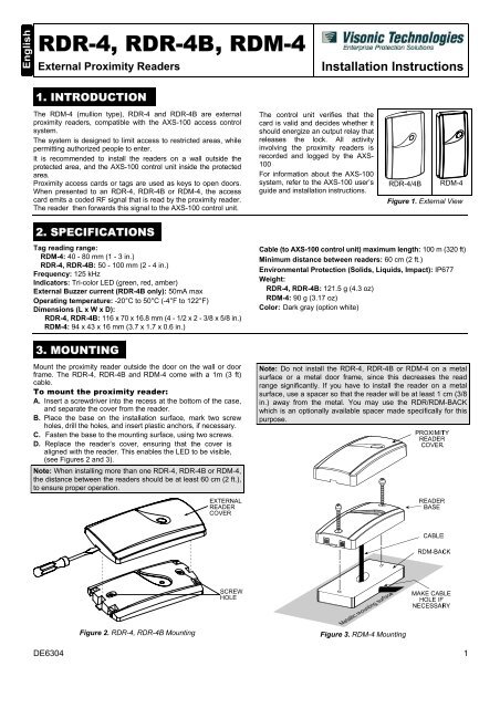
1. INTRODUCTION<br />
The <strong>RDM</strong>-4 (mullion type), <strong>RDR</strong>-4 and <strong>RDR</strong>-<strong>4B</strong> are external<br />
proximity readers, compatible with the AXS-100 access control<br />
system.<br />
The system is designed to limit access to restricted areas, while<br />
permitting authorized people to enter.<br />
It is recommended to install the readers on a wall outside the<br />
protected area, and the AXS-100 control unit inside the protected<br />
area.<br />
Proximity access cards or tags are used as keys to open doors.<br />
When presented to an <strong>RDR</strong>-4, <strong>RDR</strong>-<strong>4B</strong> or <strong>RDM</strong>-4, the access<br />
card emits a coded RF signal that is read by the proximity reader.<br />
The reader then forwards this signal to the AXS-100 control unit.<br />
The control unit verifies that the<br />
card is valid and decides whether it<br />
should energize an output relay that<br />
releases the lock. All activity<br />
involving the proximity readers is<br />
recorded and logged by the AXS-<br />
100<br />
For information about the AXS-100<br />
system, refer to the AXS-100 user’s<br />
guide and installation instructions.<br />
<strong>RDR</strong>-4/<strong>4B</strong><br />
<strong>RDM</strong>-4<br />
Figure 1. External View<br />
2. SPECIFICATIONS<br />
Tag reading range:<br />
<strong>RDM</strong>-4: 40 - 80 mm (1 - 3 in.)<br />
<strong>RDR</strong>-4, <strong>RDR</strong>-<strong>4B</strong>: 50 - 100 mm (2 - 4 in.)<br />
Frequency: 125 kHz<br />
Indicators: Tri-color LED (green, red, amber)<br />
External Buzzer current (<strong>RDR</strong>-<strong>4B</strong> only): 50mA max<br />
Operating temperature: -20°C to 50°C (-4°F to 122°F)<br />
Dimensions (L x W x D):<br />
<strong>RDR</strong>-4, <strong>RDR</strong>-<strong>4B</strong>: 116 x 70 x 16.8 mm (4 - 1/2 x 2 - 3/8 x 5/8 in.)<br />
<strong>RDM</strong>-4: 94 x 43 x 16 mm (3.7 x 1.7 x 0.6 in.)<br />
Cable (to AXS-100 control unit) maximum length: 100 m (320 ft)<br />
Minimum distance between readers: 60 cm (2 ft.)<br />
Environmental Protection (Solids, Liquids, Impact): IP677<br />
Weight:<br />
<strong>RDR</strong>-4, <strong>RDR</strong>-<strong>4B</strong>: 121.5 g (4.3 oz)<br />
<strong>RDM</strong>-4: 90 g (3.17 oz)<br />
Color: Dark gray (option white)<br />
3. MOUNTING<br />
Mount the proximity reader outside the door on the wall or door<br />
frame. The <strong>RDR</strong>-4, <strong>RDR</strong>-<strong>4B</strong> and <strong>RDM</strong>-4 come with a 1m (3 ft)<br />
cable.<br />
To mount the proximity reader:<br />
A. Insert a screwdriver into the recess at the bottom of the case,<br />
and separate the cover from the reader.<br />
B. Place the base on the installation surface, mark two screw<br />
holes, drill the holes, and insert plastic anchors, if necessary.<br />
C. Fasten the base to the mounting surface, using two screws.<br />
D. Replace the reader’s cover, ensuring that the cover is<br />
aligned with the reader. This enables the LED to be visible,<br />
(see Figures 2 and 3).<br />
Note: When installing more than one <strong>RDR</strong>-4, <strong>RDR</strong>-<strong>4B</strong> or <strong>RDM</strong>-4,<br />
the distance between the readers should be at least 60 cm (2 ft.),<br />
to ensure proper operation.<br />
Note: Do not install the <strong>RDR</strong>-4, <strong>RDR</strong>-<strong>4B</strong> or <strong>RDM</strong>-4 on a metal<br />
surface or a metal door frame, since this decreases the read<br />
range significantly. If you have to install the reader on a metal<br />
surface, use a spacer so that the reader will be at least 1 cm (3/8<br />
in.) away from the metal. You may use the <strong>RDR</strong>/<strong>RDM</strong>-BACK<br />
which is an optionally available spacer made specifically for this<br />
purpose.<br />
Figure 2. <strong>RDR</strong>-4, <strong>RDR</strong>-<strong>4B</strong> Mounting<br />
Figure 3. <strong>RDM</strong>-4 Mounting<br />
DE6304 1
4. WIRING<br />
The standard cable is color-coded. Use a cable with the same<br />
colors to avoid mistakes in connection. Connect each proximity<br />
reader to the reader sections on the AXS-100 connector blocks.<br />
4.1 Wiring the <strong>RDR</strong>-4<br />
Each <strong>RDR</strong>-4 proximity reader is connected to the control unit via<br />
a four-wire cable. See Figure 4 for color-coding.<br />
FROM<br />
<strong>RDR</strong>-4<br />
READER<br />
RED<br />
BLACK<br />
GREEN<br />
WHITE<br />
PWR<br />
GND<br />
TX<br />
RX<br />
Figure 4. <strong>RDR</strong> 4 Color-Coding<br />
4.2 Wiring the <strong>RDR</strong>-<strong>4B</strong><br />
AXS-100<br />
TERMINAL<br />
BLOCK<br />
The <strong>RDR</strong>-<strong>4B</strong> in conjunction with the AXS-100, facilitates a door ajar<br />
annunciation next to each door. The <strong>RDR</strong>-<strong>4B</strong> connects to the AXS-<br />
100 controller using the same four color wire as the <strong>RDR</strong>-4. The<br />
two extra wires (brown and blue) should be connected to a local<br />
12V / 50mA buzzer as follows:<br />
• Brown wire to buzzer +<br />
• Blue wire to buzzer -<br />
The output current is limited to 50mA. See Figure 5 for color coding.<br />
For activating the output of <strong>RDR</strong>-<strong>4B</strong> refer to the AXS-100 User<br />
Guide section 5.2.3.<br />
FROM<br />
<strong>RDR</strong>-<strong>4B</strong><br />
READER<br />
BROWN<br />
BLUE<br />
RED<br />
BLACK<br />
GREEN<br />
WHITE<br />
BUZZER<br />
PWR<br />
GND<br />
TX<br />
RX<br />
Figure 5. <strong>RDR</strong>-<strong>4B</strong> Color-Coding<br />
4.3 Wiring the <strong>RDM</strong>-4<br />
AXS-100<br />
TERMINAL<br />
BLOCK<br />
Each <strong>RDM</strong>-4 proximity reader is connected to the control unit via<br />
a four-wire cable. See Figure 6 for color-coding.<br />
TO <strong>RDM</strong>-4<br />
READER<br />
RED<br />
BLACK<br />
GREEN<br />
WHITE<br />
PWR<br />
GND<br />
TX<br />
RX<br />
Figure 6. <strong>RDM</strong>-4 Color-Coding<br />
AXS-100<br />
TERMINAL<br />
BLOCK<br />
This device complies with the essential requirements and provisions of Directive 1999/5/EC of the European Parliament and of the Council of 9<br />
March 1999 on radio and telecommunications terminal equipment.<br />
WARRANTY<br />
<strong>Visonic</strong> <strong>Technologies</strong> Ltd. and/or its subsidiaries and its affiliates ("the Manufacturer")<br />
warrants its products hereinafter referred to as "the Product" or "Products" to be in<br />
conformance with its own plans and specifications and to be free of defects in materials<br />
and workmanship under normal use and service for a period of twelve months from the<br />
date of shipment by the Manufacturer. The Manufacturer's obligations shall be limited<br />
within the warranty period, at its option, to repair or replace the product or any part<br />
thereof. The Manufacturer shall not be responsible for dismantling and/or reinstallation<br />
charges. To exercise the warranty the product must be returned to the Manufacturer<br />
freight prepaid and insured.<br />
This warranty does not apply in the following cases: improper installation, misuse,<br />
failure to follow installation and operating instructions, alteration, abuse, accident or<br />
tampering, and repair by anyone other than the Manufacturer.<br />
This warranty is exclusive and expressly in lieu of all other warranties, obligations or<br />
liabilities, whether written, oral, express or implied, including any warranty of<br />
merchantability or fitness for a particular purpose, or otherwise. In no case shall the<br />
Manufacturer be liable to anyone for any consequential or incidental damages for breach<br />
of this warranty or any other warranties whatsoever, as aforesaid.<br />
This warranty shall not be modified, varied or extended, and the Manufacturer does not<br />
authorize any person to act on its behalf in the modification, variation or extension of this<br />
warranty. This warranty shall apply to the Product only. All products, accessories or<br />
attachments of others used in conjunction with the Product, including batteries, shall be<br />
covered solely by their own warranty, if any. The Manufacturer shall not be liable for any<br />
damage or loss whatsoever, whether directly, indirectly, incidentally, consequentially or<br />
otherwise, caused by the malfunction of the Product due to products, accessories, or<br />
attachments of others, including batteries, used in conjunction with the Products.<br />
The Manufacturer does not represent that its Product may not be compromised and/or<br />
circumvented, or that the Product will prevent any death, personal and/or bodily injury<br />
and/or damage to property resulting from burglary, robbery, fire or otherwise, or that the<br />
Product will in all cases provide adequate warning or protection. User understands that a<br />
properly installed and maintained alarm may only reduce the risk of events such as<br />
burglary, robbery, and fire without warning, but it is not insurance or a guarantee that<br />
such will not occur or that there will be no death, personal damage and/or damage to<br />
property as a result.<br />
The Manufacturer shall have no liability for any death, personal and/or bodily injury<br />
and/or damage to property or other loss whether direct, indirect, incidental,<br />
consequential or otherwise, based on a claim that the Product failed to function.<br />
However, if the Manufacturer is held liable, whether directly or indirectly, for any loss or<br />
damage arising under this limited warranty or otherwise, regardless of cause or origin, the<br />
Manufacturer's maximum liability shall not in any case exceed the purchase price of the<br />
Product, which shall be fixed as liquidated damages and not as a penalty, and shall be<br />
the complete and exclusive remedy against the Manufacturer.<br />
Warning: The user should follow the installation and operation instructions and among<br />
other things test the Product and the whole system at least once a week. For various<br />
reasons, including, but not limited to, changes in environmental conditions, electric or<br />
electronic disruptions and tampering, the Product may not perform as expected. The user<br />
is advised to take all necessary precautions for his /her safety and the protection of<br />
his/her property.<br />
6/91<br />
VISONIC TECHNOLOGIES. (ISRAEL): 30 Habarzel St. Tel Aviv 69710 ISRAEL Tel 972-3-7681400 Fax: 972-3-7681415 E-MAIL: support@visonictech.com<br />
VTA (VISONIC TECHNOLOGIES AMERICAS): 65 West Dudley Town Road, Bloomfield CT. 06002-1911 USA. TEL.: (860) 243 0833, (800) 223 0020<br />
FAX: (860) 242-8094. E-MAIL: usa_support@visonic.com<br />
VT UK (VISONIC TECHNOLOGIES UK): Fraser Road, Priory Business Park, Bedford MK44 3WH ENGLAND. TEL.: 44-870-730-0840; FAX: 44-870-730-0839<br />
INTERNET: www.visonictech.com<br />
©VISONIC TECHNOLOGIES LTD. 2004 <strong>RDR</strong>-4, <strong>RDR</strong>-<strong>4B</strong>, <strong>RDM</strong>-4 DE6304- (REV. 2, 9/03)<br />
2 DE6304