Da!iGEâ HINGED CAP PILLOW BLOCKS - PTplace.com
Da!iGEâ HINGED CAP PILLOW BLOCKS - PTplace.com
Da!iGEâ HINGED CAP PILLOW BLOCKS - PTplace.com

Create successful ePaper yourself
Turn your PDF publications into a flip-book with our unique Google optimized e-Paper software.
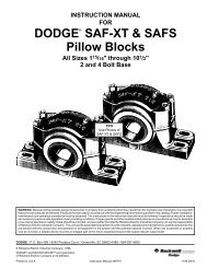
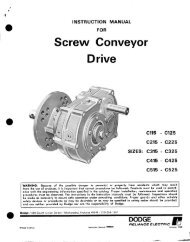
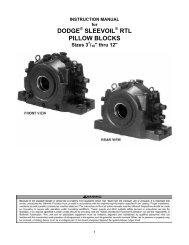
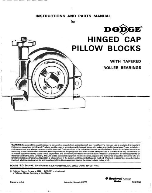
INSTRUCTIONS AND PARTS MANUAL<br />
for<br />
<strong>Da</strong>!iGE”<br />
<strong>HINGED</strong> <strong>CAP</strong><br />
<strong>PILLOW</strong> <strong>BLOCKS</strong><br />
WITH<br />
ROLLER<br />
TAPERED<br />
BEARINGS<br />
WARNING: Because of the possible danger to person(s) or property from accidents which may result from the improper use of products, it is important<br />
that correct procedures be followed. Products must be used in accordance with the engineering information specified in the catalog. Proper installation,<br />
maintenance and operation procedures must be observed. The instructions in the instruction manuals must be followed. Inspections should be made as<br />
necessary to assure safe operation under prevailing conditions. Proper guards and other suitable safety devices or procedures as may be desirable or<br />
as may be specified in safety codes should be provided, and are neither provided by Reliance Electric Industrial Company nor are the responsibility of<br />
Reliance Electric Industrial Company. This unit and its associated equipment must be installed, adjusted and maintained by qualified personnel who are<br />
familiar with the construction and operation of all equipment in the system and the potential hazards invofved. When risk to persons or property may be<br />
invofved, a holding device must be an integral part of the driven equipment beyond the speed reducer output shaft.<br />
DODGE I P.O. Box 499 / 6040 Ponders Court / Greenville, SC. 29602-0499 I 864-297-4800<br />
6 Reliance Electric Company, 1996 DODGEe is a trademark<br />
of Reliance Electric Company or its affiliates.<br />
m Rtinrell Automation<br />
Printed in U.S.A. Instruction Manual 499772<br />
5K-K 9i99
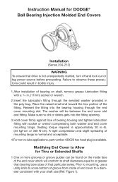
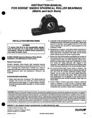
INSTALLATION<br />
INSTRUCTIONS*<br />
Installing Bearing on Shaft:<br />
WARNING<br />
To ensure that drive is not unexpectedly started, turn off<br />
and lock out or tag power source before proceeding.<br />
Failure to observe these precautions could result in<br />
bodily injury.<br />
13.<br />
are very tight, it may be advisable to loosen adapter<br />
to move slightly on shaft.<br />
Expansion Bearing: Inner unit should be located with<br />
unit housing in center of outer housing so unit can move<br />
freely in either direction. Loosen hand knob in outer<br />
housing a little so unit is free to align in outer housing.<br />
Tighten hold-down bolts. Retighten hand knob.<br />
L<br />
1.<br />
2.<br />
3.<br />
4.<br />
5.<br />
6.<br />
8.<br />
Install non-expansion bearing first.<br />
Shaft should be within <strong>com</strong>mercial tolerances, straight,<br />
smooth and clean. Apply a thin coat of light oil on the<br />
shaft.<br />
Back off setscrews (63) until they are stopped by<br />
deformed threads in end of adapter (61).<br />
If necessary to expand adapter (61) loosen adapter nut<br />
(57) and tap on end of this nut.<br />
Slide bearing on shaft and locate where desired.<br />
Do not bolt outer housing to support until bearing<br />
is tightened on shaft.<br />
bearing.<br />
V-v;’<br />
tore%t&+e weight from<br />
To keep adapter (61) from turning on shaft, tap on large<br />
end opposite adapter nut. If large end of adapter is<br />
inaccessible, insert point of screwdriver between housing<br />
(89) and adapter nut (57) and twist screwdriver.<br />
14.<br />
Non-Expansion Bearing: Loosen hand knob in outer<br />
housing a little so unit is free to align in outer housing.<br />
Tighten hold-down bolts. Retighten hand knob.<br />
After a short run make sure adapter is tight as follows:<br />
loosen hold-down bolts and unlock ad;rn+sr nut by<br />
bending out prong; perform steps> 9, 10 and 11.<br />
Tighten hold-d&h bolts/ ’<br />
Removing Bearing from Shaft:<br />
WARNING<br />
To ensure that drive is not unexpectedly started, turn off<br />
and look et&-g f=w=ew=bef~~<br />
Failure to observe these precautions could result in<br />
bodily injury.<br />
1. Unlock adapter nut (57) by bending out prong of adapter<br />
nut lock washer (58).<br />
’<br />
P‘<br />
I<br />
9.<br />
10.<br />
11.<br />
Tighten (turn clockwise) adapter nut with wrench.<br />
When considerable effort is required to turn adapter<br />
nut, hammer on end of nut using a soft steel or brass<br />
drift while turning with wrench. When adapter seems to<br />
be tight, also use a hammer on the wrench while hammering<br />
simultaneously on end of adapter nut.<br />
Lock adapter nut by bending one prong of lock washer<br />
(58) into corresponding notch in back of the nut.<br />
Important: - Never loosen adapter nut to next<br />
locking position.<br />
2. Loosen hold-down bolts. Block up shaft, if possible, to<br />
remove weight from bearing.<br />
3. Loosen adapter nut about one turn, and tighten setscrews<br />
(63) on opposite end of bearing until tapered<br />
roller bearing cone is free on adapter. Bearing can then<br />
be pushed off the shaft. If difficulty is encountered<br />
dislodging the cone, it is suggested to hammer simultaneously<br />
on end of adapter nut using a drift rod while<br />
tightening setscrews (63) on opposite end of bearing.<br />
12.<br />
Check hold-down bolts in outer housing to see that<br />
they are loose and free. (If too tight, an excessive<br />
thrust load could be imposed on bearing.) If bolts<br />
I<br />
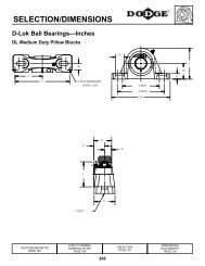
*Hinged cap pillow blocks must be base loaded.
LUBRICATION<br />
Normal Operation -This bearing has been greased at the<br />
factory and is ready to run. The following table is a general<br />
guide for relubrication. However, certain conditions may<br />
require a change of lubricating periods as dictated by experience.<br />
See “High Speed Operation” and “Operation in<br />
Presence of Dust, Water or Corrosive Vapors.”When establishing<br />
a relubrication schedule, note that a small amount of<br />
grease at frequent intervals is preferable to a large amount<br />
at infrequent intervals.<br />
Lubrication Guide<br />
Suggested Lubrication Period in Weeks<br />
1 to I251 to1501 to1751 tol1001 to11501 to 12001 to12501 to<br />
8 12 12 10 7 5 4 3 2<br />
16 12 7 5 4 2 2 2 1<br />
24 10 5 3 2 1 1 1 1<br />
Operating Temperature - Bearing inner unit housing<br />
temperature at or above 175°F may indicate faulty lubri-<br />
[t_<br />
ac<strong>com</strong>panied by excessive leakage of grease indicates too<br />
much grease. 175°F or higher temperature with no grease<br />
showing at the seals, particularly if the bearing seems<br />
noisy, usually indicates too little grease. Temperature<br />
below 175°F and a slight showing of grease at the seals<br />
indicate proper lubrication.<br />
High Speed Operation - In the higher speed ranges too<br />
much grease will cause overheating. The amount of grease<br />
that the bearing will take for a particular high speed application<br />
can only be determined by experience - see<br />
“Operating Temperature.” If excess grease in the bearing<br />
causes overheating, it will be necessary to remove grease<br />
INSTRUCTIONS<br />
fitting (also drain plug when furnished) to permit excess<br />
grease to escape.<br />
Operation in Presence of Dust, Water or Corrosive<br />
Vapors - Under these conditions the bearing should contain<br />
as much grease as speed will permit, since a full<br />
bearing with consequent slight leakage is the best protection<br />
against entrance of foreign material. In the higher speed<br />
ranges too much grease will cause overheating -see “High<br />
Speed Operation.” In the lower speed ranges it is advisable<br />
to add extra grease to a new bearing before putting into<br />
operation. Bearings should be greased as often as necessary<br />
(daily if required) to maintain a slight leakage at the<br />
seals.<br />
Special Operating Conditions - Refer acid, chemical,<br />
extreme or other special operating conditions to DODGE/<br />
RELIANCE ELECTRIC, Greenville, South Carolina (864<br />
297-4800); Attn.: Application Engineering.<br />
conditions or to corrosive vapors, extra protection is necessary;<br />
Add grease until it shows at the seals; rotate the<br />
bearing to distribute grease; cover the bearing. After storage<br />
or idle period, add a little fresh grease before running.<br />
Kind of Grease - Many ordinary cup greases will disintegrate<br />
at speeds far below those at which DODGE bearings<br />
will operate successfully if proper grease is used. DODGE<br />
bearings have been lubricated at the factory with No. 2<br />
consistency lithium-base grease. Relubricate with lithiumbase<br />
grease or a grease which is <strong>com</strong>patible with original<br />
lubricant and suitable for roller bearing service. In unusual<br />
or doubtful cases the re<strong>com</strong>mendation of a reputable<br />
grease manufacturer should be secured.
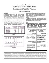
NOTE: The two<br />
digit numbers ore<br />
for reference only.<br />
Order parts by the<br />
six digit numbers<br />
in the Parts List.<br />
Each six digit<br />
number is a <strong>com</strong>plete<br />
identification<br />
of the part or assembly.<br />
EXPANSION<br />
SHOWN<br />
P.S.<br />
Parts for Hinged Cap Pillow Blocks<br />
Rcference<br />
Noma of Part<br />
61 Micro De-Mount Adapter (One Required)<br />
I I I I I<br />
Part Numbers for Various Shaft Sires<br />
2% 2% 2% 2% . .._..<br />
067127 W7142 067147 067085<br />
--