Program Information Mobile Hydraulics, Mobile ... - Bosch Rexroth AG
Program Information Mobile Hydraulics, Mobile ... - Bosch Rexroth AG
Program Information Mobile Hydraulics, Mobile ... - Bosch Rexroth AG

You also want an ePaper? Increase the reach of your titles
YUMPU automatically turns print PDFs into web optimized ePapers that Google loves.
Electric Drives<br />
and Controls<br />
<strong>Hydraulics</strong><br />
<strong>Program</strong> <strong>Information</strong><br />
<strong>Mobile</strong> <strong>Hydraulics</strong>,<br />
<strong>Mobile</strong> Electronics, Gears<br />
The Drive & Control Company<br />
Linear Motion and<br />
Assembly Technologies Pneumatics<br />
Service
Welcome to the World of <strong>Mobile</strong> <strong>Hydraulics</strong><br />
<strong>Rexroth</strong> can supply all the components,<br />
modules and systems you<br />
need to drive and control your mobile<br />
machines mechanically, hydraulically<br />
and electronically. In<br />
<strong>Mobile</strong> <strong>Hydraulics</strong> <strong>Rexroth</strong> is offering<br />
a portfolio of products unrivalled<br />
on the market, consisting<br />
of axial piston units, external gear<br />
units, radial piston motors, mobile<br />
controls, compact hydraulics, gears,<br />
mobile electronics and service.<br />
The hydraulic solutions supplied<br />
by our company are “cast in one”,<br />
so that you can rely on components<br />
and services that are among the<br />
best in their class. Ours is the largest<br />
and most extensive range of<br />
mobile hydraulics products in the<br />
world.<br />
In addition, you can also profit<br />
from our unique industry, applications<br />
and development know-how.<br />
Our engineers analyze your requirements<br />
our in special Applications<br />
Centers.<br />
This way, complete operational system<br />
solutions with perfectly matched<br />
components and the fewest<br />
possible interfaces are developed<br />
in close cooperation with you. The<br />
synergistic potential inherent in<br />
our association with <strong>Bosch</strong> is consistently<br />
utilized. Supplementary<br />
services and worldwide customer<br />
service are further integral parts of<br />
our range.<br />
In short: <strong>Rexroth</strong> is your competent<br />
partner and supplier for all<br />
drive and control systems for mobile<br />
machines.<br />
Axial Piston Units<br />
External Gear Units<br />
Radial Piston Motors<br />
<strong>Mobile</strong> Controls<br />
Compact <strong>Hydraulics</strong><br />
Gears<br />
BODAS <strong>Mobile</strong> Electronics<br />
Accumulators<br />
3<br />
1<br />
2<br />
3<br />
4<br />
5<br />
6<br />
7<br />
8
4<br />
1<br />
2<br />
3<br />
4<br />
Contents<br />
Axial Piston Units 9<br />
Fixed pumps A2FO 10<br />
A4FO 11<br />
KFA 12<br />
Variable pumps KVA 13<br />
A10VO/5 14<br />
A10VNO 15<br />
A10VO/3 16<br />
A11VO 17<br />
A4VSO 18<br />
A7VO 19<br />
A20VO 20<br />
A8VO 21<br />
A4VG 22<br />
A10VG 23<br />
A4VTG 24<br />
A4CSG 25<br />
Fixed motors A2FM 26<br />
A4FM 27<br />
A10FM 28<br />
Variable motors A6VM 29<br />
A10VM 30<br />
External Gear Units 31<br />
External gear pumps Standard version 32<br />
SILENCE version 34<br />
External gear motors 35<br />
Hydrostatic fan drive 36<br />
Radial Piston Motors 37<br />
Radial piston motors MCR 38<br />
<strong>Mobile</strong> Controls 41<br />
Control blocks Open Center control block SM 42<br />
Open Center control block MO 43<br />
Open Center control block M8 44<br />
LUDV control block SX 45<br />
LUDV control block M6 46<br />
LUDV control block M7 47<br />
Load sensing control block SP-08 48<br />
Load sensing control block M4 49<br />
Load sensing control block SB12-LS 50<br />
Load sensing control block SB23-LS 51<br />
Valve modules Control valves EHR 52<br />
Central hydraulics for tractors CHP 53<br />
Flow divider MH2FA/RTM 54<br />
Pipe burst safety valves MHRB 55<br />
Check-Q-meter FD 55<br />
Stabilizing module RSM2 56<br />
Pilot oil supply systems MHSTE 56<br />
Pressure, flow, check valves 57
Brakes Hydraulic remotely powered brakes LT 58<br />
Trailer brake valves BV1 59<br />
Steering units Hydrostatic steering units L<strong>AG</strong> 60<br />
Priority valves LPS 61<br />
Steering columns LAB and sensors 61<br />
Pilot control devices Hydraulic and electronic pilot control devices TH 62<br />
Compact <strong>Hydraulics</strong> 63<br />
Cartridge valves: Counterbalance valves 64<br />
Mechanical valves 65<br />
Solenoid operated directional valves, poppet type 66<br />
Solenoid operated direct. poppet valves KSDE and directional spool valves KKDE 67<br />
Prop. pressure relief valves KB.S and pressure reducing valves FTDRE / MHDRE 68<br />
Insert type valves 69<br />
Standard manifolds 70<br />
Customized integrated circuits 71<br />
Pressure, flow, pilot operated check valves 72<br />
Motion control valves 73<br />
Cylinder safety lock valve – A-VBC 74<br />
Heavy duty priority flow control 75<br />
Compact power module Series KE 76<br />
Series K 77<br />
Series ME 78<br />
Inline valves 79<br />
Flow diverters 80<br />
Modular directional valves 81<br />
CETOP 2 (NG4) 82<br />
Special directional valves 83<br />
Gears 85<br />
Travel drives HYDROTRAC GFT 86<br />
HYDROTRAC GFT-A10VT 87<br />
Swing drives MOBILEX GFB 88<br />
MOBILEX GFB-A10FD 89<br />
Winch drives MOBILEX GFT-W 90<br />
Planetary gearboxes REDULUS GMH/GME 91<br />
Generator gear units REDULUS GPV for wind turbines from 300 to 5,000 kW 92<br />
Pitch and yaw drives MOBILEX GFB 93<br />
BODAS <strong>Mobile</strong> Electronics 95<br />
BODAS controller RC 96<br />
BODAS application software 97<br />
BODAS tools 98<br />
BODAS sensors 99<br />
BODAS joysticks and display 100<br />
Analog amplifier RA 101<br />
Electrohydraulic hitch control for tractors EHR 102<br />
Electrohydraulic header height control EMR 103<br />
Automatic fan control AFC 104<br />
Accumulators 105<br />
Hydropneumatic accumulators and accessories for accumulators 106<br />
5<br />
5<br />
6<br />
7<br />
8
6<br />
Application Examples<br />
Wheel, crawler and mining excavators, mini-excavators, backhoe loaders, wheel loaders, skid steer loaders,<br />
crawler loaders, bulldozers, road rollers, pavers<br />
Drilling equipment, cranes, fork lift trucks, telehandlers,<br />
straddle carrier, aerial work platforms, snow groomers<br />
Concrete pumps, mobile concrete mixers, commercial vehicles,<br />
municipal vehicles, forestry machinery, agricultural machinery, wind power plants
Products of <strong>Mobile</strong> <strong>Hydraulics</strong><br />
Axial Piston Units<br />
External Gear Units<br />
Radial Piston Motors<br />
<strong>Mobile</strong> Controls<br />
Compact <strong>Hydraulics</strong><br />
Gears<br />
BODAS <strong>Mobile</strong> Electronics<br />
Accumulators<br />
Fixed Pumps, Variable Pumps, Fixed Motors, Variable Motors<br />
External Gear Pumps, External Gear Motors, Fan Motors<br />
Control Blocks, Valve Module, Brakes, Steering Units, Pilot Control Devices<br />
Cartridge Valves, Integrated Circuits, Load Holding / Motion Control Valves,<br />
Power Modules, Compact Directional Valves<br />
Travel Drives, Swing Drives, Winch Drives,<br />
Planetary Gearboxes, Generator Gear Units, Pitch and Yaw Drives<br />
Controllers, Amplifiers, Sensors, Joysticks, Displays, Parameterization and<br />
<strong>Program</strong>ming Tools, Application Software and System Solutions<br />
Hydropneumatic Accumulators and Accessories for Accumulators<br />
7<br />
1<br />
2<br />
3<br />
4<br />
5<br />
6<br />
7<br />
8
Axial Piston Units<br />
Axial piston units are available in<br />
the form of pumps and motors in<br />
bent axis design or swashplate design<br />
for medium- and high-pressure<br />
ranges. They are the main<br />
components in the hydrostatic<br />
transmission. Compact size and<br />
high power density, economy and<br />
reliability are characteristic advantages<br />
promoting the use of hydrostatic<br />
transmissions, together with<br />
the fact that they meet the demand<br />
for high speed and high torque, as<br />
well as optimum efficiency.<br />
Characteristics:<br />
- Open and/or closed circuit<br />
- Displacement 5 to 1000 cm 3<br />
- Nominal pressure up to 450 bar<br />
- Maximum speed up to<br />
11,000 rpm<br />
- Maximum power output 933 kW<br />
Our versatile transmissions for mobile<br />
applications can be combined<br />
in a variety of ways with pumps,<br />
motors and open or closed loop<br />
control devices to offer the optimum<br />
design for every drive application<br />
and every power range.<br />
Key advantages:<br />
- Infinitely variable speed setting at<br />
fixed or variable input speed<br />
- Immediate, jolt-free change in<br />
direction of rotation<br />
- Simple, ergonomic operation<br />
- High turnaround<br />
- Automatic torque conversion<br />
Axial piston pumps and motors are<br />
used for the travel drive and working<br />
hydraulics in a wide variety of<br />
mobile machines.<br />
9<br />
1
10 Axial Piston Units<br />
1<br />
Fixed Pump A2FO<br />
Sizes 5...1000<br />
Axial tapered piston bent axis design<br />
Series 6<br />
Open circuits<br />
Nominal pressure<br />
Size 5: 315 bar<br />
Sizes 10...200: 400 bar<br />
Sizes 250...1000: 350 bar<br />
Peak pressure<br />
Size 5: 350 bar<br />
Sizes 10...200: 450 bar<br />
Sizes 250...1000: 400 bar<br />
The standard fixed pump for all<br />
fields of application in open circuits.<br />
- Service ports SAE flange or<br />
thread<br />
- Shaft end parallel with key or<br />
spline shaft<br />
- Long-life bearings available (sizes<br />
250...1000)<br />
Detailed information:<br />
A2FO RE 91401<br />
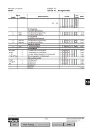
Size 5 10 12 16 23 28 32 45 56 63 80<br />
Displacement Vg cm³ 4,93 10,3 12 16 22,9 28,1 32 45,6 56,1 63 80,4<br />
Speed 1) nmax rpm 5600 3150 3150 3150 2500 2500 2500 2240 2000 2000 1800<br />
Flow at nmax qVmax l/min 27,6 32,4 37,8 50 57 70 80 102 112 126 144<br />
Power Δp = 315 bar Pmax kW 14,5 - - - - - - - - - -<br />
Power Δp = 400 bar Pmax kW - 21,6 25 34 38 47 53 68 75 84 96<br />
Torque Δp = 315 bar Tmax Nm 24,7 - - - - - - - - - -<br />
Torque Δp = 400 bar Tmax Nm - 65 76 101 145 178 203 290 356 400 511<br />
Weight (approx.) m kg 2,5 6 6 6 9,5 9,5 9,5 13,5 18 18 23<br />
Size 90 107 125 160 180 200 250 355 500 710 1000<br />
Displacement Vg cm³ 90 106,7 125 160,4 180 200 250 355 500 710 1000<br />
Speed 1) nmax rpm 1800 1600 1600 1450 1450 1550 1500 1320 1200 1200 950<br />
Flow at nmax qVmax l/min 162 170 200 232 261 310 375 469 600 826 950<br />
Power Δp = 350 bar Pmax kW - - - - - - 219 273 350 497 554<br />
Power Δp = 400 bar Pmax kW 108 114 133 155 174 207 - - - - -<br />
Torque Δp = 350 bar Tmax Nm - - - - - - 1393 1978 2785 3955 5570<br />
Torque Δp = 400 bar Tmax Nm 572 678 795 1020 1145 1272 - - - - -<br />
Weight (approx.) m kg 23 32 32 45 45 66 73 110 155 322 336<br />
¹) These values are valid at an absolute pressure of 1 bar in suction port S
Fixed Pump A4FO<br />
Sizes 16...500<br />
Axial piston swashplate design<br />
Series 3<br />
Sizes 16...40 and 125...500<br />
Series 1<br />
Size 71<br />
Open circuits<br />
Nominal pressure<br />
Sizes 16...40: 400 bar<br />
Sizes 71...500: 350 bar<br />
Peak pressure<br />
Sizes 16...40: 450 bar<br />
Sizes 71...500: 400 bar<br />
Fixed pump with possibility of through<br />
drive for mounting further<br />
pumps up to the same size.<br />
Operation possible with HF hydraulic<br />
fluids with reduced data<br />
(sizes 71...500).<br />
Detailed information:<br />
A4FO RE 91455<br />
Size 16 22 28 40 71 125 250 500<br />
Displacement Vg cm³ 16 22 28 40 71 125 250 500<br />
Speed 1) 2) nmax rpm 4000 3600 3000 2750 2200 1800 1500 1320<br />
Flow at nmax qVmax l/min 64 79 84 110 152 225 375 660<br />
Power Δp = 350 bar Pmax kW - - - - 91 131 219 385<br />
Power Δp = 400 bar Pmax kW 43 53 56 73 - - - -<br />
Torque Δp = 350 bar Tmax Nm - - - - 395 696 1391 2783<br />
Torque Δp = 400 bar Tmax Nm 102 140 178 254 - - - -<br />
Weight (approx.) m kg 13,5 13,5 13,5 16,5 34 61 120 220<br />
¹) These values are valid at an absolute pressure of 1 bar in suction port S<br />
²) Higher speeds permissible for high-speed version (sizes 250, 500)<br />
11<br />
1
12 Axial Piston Units<br />
1<br />
Fixed Pump KFA<br />
Sizes 23...125<br />
Axial tapered piston bent axis design<br />
Series 6<br />
Open circuits<br />
Nominal pressure<br />
Sizes 23...107: 300 bar<br />
Size 125: 250 bar<br />
Peak pressure<br />
Sizes 23...107: 350 bar<br />
Size 125: 300 bar<br />
Fixed pump for working equipment<br />
in commercial vehicles, such<br />
as street tippers, dump trucks,<br />
HGV loading cranes, tankers, municipal<br />
vehicles, special vehicles, etc.<br />
These pumps are compatible with<br />
the standardized power take-offs<br />
on HGV motors and gearboxes according<br />
to European standards.<br />
They fulfill all requirements placed<br />
on hydraulic drives in these areas.<br />
- No case drain line required<br />
- Simple change of direction of rotation<br />
Detailed information:<br />
KFA RE 91501<br />
Size 23 32 45 63 80 107 125<br />
Displacement Vg cm³ 22,9 32 45,6 63 80,4 106,7 125<br />
Speed 1) nmax rpm 2920 2900 2560 2300 2130 1860 1800<br />
Flow at nmax qVmax l/min 67 93 117 145 171 198 225<br />
Power Δp = 250 bar Pmax kW - - - - - - 94<br />
Power Δp = 300 bar Pmax kW 33 46 58 73 86 99 -<br />
Torque Δp = 250 bar Tmax Nm - - - - - - 497<br />
Torque Δp = 300 bar Tmax Nm 109 153 218 301 384 509 -<br />
Weight (approx.) m kg 5,8 5,8 8 9 11,6 14,5 14,5<br />
¹) These values are valid at an absolute pressure of 1 bar in suction port S
Variable Pump KVA<br />
Sizes 55...107<br />
Axial tapered piston bent axis design<br />
Series 6<br />
Open circuits<br />
Nominal pressure: 300 bar<br />
Peak pressure: 350 bar<br />
Variable pump for demanding<br />
applications and easy control of<br />
working equipment in commercial<br />
vehicles, e.g. HGV loading cranes,<br />
generator drives, compressor<br />
drives, drives for air conditioning<br />
systems, fan drives, etc.<br />
These pumps are compatible with<br />
the standardized power take-offs<br />
on HGV motors and gearboxes according<br />
to European standards.<br />
They fulfill all requirements placed<br />
on hydraulic drives in these areas.<br />
Size 55 80 107<br />
Displacement Vg max cm³ 54,8 80 107<br />
Speed 1) at Vg max nmax rpm 2500 2240 2150<br />
Flow at nmax qVmax l/min 137 179 230<br />
Power Δp = 300 bar Pmax kW 68 90 115<br />
Torque Δp = 300 bar Tmax Nm 261 382 510<br />
Weight (approx.) m kg 16 20 24<br />
¹) These values are valid at an absolute pressure of 1 bar in suction port S<br />
DRS<br />
EP<br />
Pressure control with Electrical control,<br />
load sensing function with proportional<br />
solenoid<br />
p B<br />
Vg min<br />
Vg max<br />
I<br />
Vg min<br />
Vg max<br />
Detailed information:<br />
KVA RE 92250<br />
Vg = Displacement<br />
pB = Operating pressure<br />
I = Control current<br />
13<br />
1
14 Axial Piston Units<br />
1<br />
Variable Pump A10VO/5<br />
Sizes 10...85<br />
Axial piston swashplate design<br />
Series 5<br />
Open circuits<br />
Nominal pressure: 250 bar<br />
Peak pressure: 315 bar<br />
Variable pump for pressure ranges<br />
up to max. 315 bar<br />
- Short recovery times and favorable<br />
power/weight ratio<br />
- Possible to mount additional<br />
pumps on through drive up to<br />
the same nominal size<br />
Size 10 *) 28 45 63 85<br />
Displacement Vg max cm³ 10,5 28 45 60 85<br />
Speed 1) 2) at Vg max nmax rpm 3600 3000 2600 2700 2500<br />
Flow at nmax qVmax l/min 38 84 117 162 212<br />
Power Δp = 250 bar Pmax kW 16 35 49 68 89<br />
Torque Δp = 250 bar Tmax Nm 42 111 179 250 338<br />
Weight (approx.) m kg 8 14 18 22 34<br />
¹) These values are valid at an absolute pressure of 1 bar in suction port S<br />
²) Higher speeds permissible for high-speed version (size 45)<br />
* A10VSO<br />
DR<br />
Pressure control<br />
p B<br />
Vg min<br />
Vg max<br />
DRF/DRS/EF ED<br />
EP/EK<br />
Pressure and flow Electrohydraulic Electroproportional<br />
control (EF: electric pressure control (not swivel angle control<br />
control)<br />
for size 10)<br />
p B<br />
Vg min<br />
Vg max<br />
p B<br />
I<br />
I<br />
Vg min<br />
Vg max<br />
Detailed information:<br />
A10VO/5 RE 92703<br />
A10VO ED RE 92707<br />
A10VO EP/EK RE 92708<br />
A10VO EF RE 92709<br />
LA<br />
Power control<br />
p B<br />
Vg min<br />
Vg max<br />
Vg = Displacement<br />
pB = Operating pressure<br />
I = Control current
Variable Pump A10VNO<br />
Sizes 28...85<br />
Axial piston swashplate design<br />
Series 5<br />
Open circuits<br />
Nominal pressure: 210 bar<br />
Peak pressure: 250 bar<br />
Variable pump for pressure ranges<br />
up to max. 250 bar<br />
- Short recovery times and favorable<br />
power/weight ratio<br />
- Compact installation size<br />
- Economical version as an alternative<br />
to fixed pumps<br />
Size 28 45 63 85<br />
Displacement Vg max cm³ 28 45 63 85<br />
Speed 1) at Vg max nmax rpm 3000 1800 2700 1800<br />
Flow at nmax qVmax l/min 84 81 170 153<br />
Power Δp = 210 bar Pmax kW 29 28 59 53<br />
Torque Δp = 210 bar Tmax Nm 94 150 210 284<br />
Weight (approx.) m kg 14 14 18 22<br />
¹) These values are valid at an absolute pressure of 1 bar in suction port S<br />
DRS<br />
Pressure and flow<br />
control<br />
p B<br />
Vg min<br />
Vg max<br />
Detailed information:<br />
A10VNO RE 92735<br />
Vg pB = Displacement<br />
= Operating pressure<br />
15<br />
1
16 Axial Piston Units<br />
1<br />
Variable Pump A10VO/3<br />
Sizes 18...140<br />
Axial piston swashplate design<br />
Series 3<br />
Open circuits<br />
Nominal pressure: 280 bar<br />
Peak pressure: 350 bar<br />
Variable pump for pressure ranges<br />
up to max. 350 bar<br />
- Possible to mount additional<br />
pumps on through drive up to<br />
the same nominal size<br />
- Large variety of controls<br />
Detailed information:<br />
A10VO/3 RE 92701<br />
A10VO ED RE 92707<br />
A10VO EF RE 92709<br />
Size 18 *) 28 45 71 100 140<br />
Displacement Vg max cm³ 18 28 45 71 100 140<br />
Speed 1) 2) at Vg max nmax rpm 3300 3000 2600 2200 2000 1800<br />
Flow at nmax qVmax l/min 59,4 84 117 156 200 252<br />
Power Δp = 280 bar Pmax kW 27,7 39 55 73 93 118<br />
Torque Δp = 280 bar Tmax Nm 80 125 200 316 445 623<br />
Weight (approx.) m kg 12 15 21 33 45 60<br />
¹) These values are valid at an absolute pressure of 1 bar in suction port S<br />
²) Higher speeds permissible for high-speed version (sizes 45 to 140)<br />
* A10VSO<br />
DR<br />
Pressure control<br />
p B<br />
Vg min<br />
Vg max<br />
DFR/EF<br />
Pressure and flow<br />
control<br />
p B<br />
Vg min<br />
Vg max<br />
DFLR<br />
FHD<br />
ED<br />
Pressure, flow, and Pilot pressure depen- Electrohydraulic<br />
power controller (not dent displ. control, pressure control<br />
for size 18)<br />
with pressure control<br />
(not for size 18)<br />
pB pSt pB Vg U<br />
= Displacement<br />
= Control voltage<br />
pB = Operating pressure<br />
pSt = Pilot pressure<br />
I = Control current<br />
Vg min Vg max<br />
Vg min Vg max<br />
I
Variable Pump A11VO<br />
Sizes 40...260<br />
Axial piston swashplate design<br />
Series 1<br />
Open circuits<br />
Nominal pressure: 350 bar<br />
Peak pressure: 400 bar<br />
A11VO/A11VLO<br />
Variable pump for high pressure<br />
ranges up to max. 400 bar<br />
Particularly high speeds are possible<br />
with version A11VLO with charging<br />
pump (impeller)<br />
- Universal through drive<br />
- Possible to mount additional<br />
pumps on through drive up to<br />
the same nominal size<br />
- Large variety of controls<br />
Detailed information:<br />
A11VO RE 92500<br />
A11VLO RE 92500<br />
Size A11VO 40 60 75 95 130 145 190 260<br />
Displacement Vg max cm³ 42 58,5 74 93,5 130 145 193 260<br />
Speed 1) at Vg max nmax rpm 3000 2700 2550 2350 2100 2200 2100 1800<br />
Flow at nmax qVmax l/min 126 158 189 220 273 319 405 468<br />
Power Δp = 350 bar Pmax kW 74 92 110 128 159 186 236 273<br />
Torque Δp = 350 bar Tmax Nm 234 326 412 521 724 808 1075 1448<br />
Weight (approx.) m kg 32 40 45 53 66 76 95 125<br />
Size A11VLO 130 145 190 260<br />
Displacement Vg max cm³ 130 145 193 260<br />
Speed 2) at Vg max nmax rpm 2500 2500 2500 2300<br />
Flow at nmax qVmax l/min 325 363 483 598<br />
Power Δp = 350 bar Pmax kW 190 211 281 349<br />
Torque Δp = 350 bar Tmax Nm 724 808 1075 1448<br />
Weight (approx.) m kg 72 73 104 138<br />
¹) These values are valid at an absolute pressure of 1 bar in suction port S<br />
²) These values are valid at an absolute pressure of 0.8 bar in suction port S<br />
DR<br />
Pressure control<br />
p B<br />
Vg min<br />
Vg max<br />
LR<br />
Power control<br />
p B<br />
Vg min<br />
Vg max<br />
HD<br />
EP<br />
Hydraulic control, Electrical control,<br />
pilot pressure depen- with proportional<br />
dent<br />
solenoid<br />
p St<br />
Vg min<br />
Vg max<br />
I<br />
Vg min<br />
Vg max<br />
Vg = Displacement<br />
PSt = Pilot pressure<br />
pB = Operating pressure<br />
I = Control current<br />
17<br />
1
18 Axial Piston Units<br />
1<br />
Variable Pump A4VSO<br />
Sizes 355...1000<br />
Axial piston swashplate design<br />
Series 3<br />
Open circuits<br />
Nominal pressure: 350 bar<br />
Peak pressure: 400 bar<br />
Variable pump for use in applications<br />
requiring very large volumes,<br />
e.g. in cranes, excavators, winches,<br />
etc.<br />
- Flexible universal through drive<br />
enables easy adaptation of the<br />
through drive<br />
Size 355 500 750 1000<br />
Displacement Vg max cm³ 355 500 750 1000<br />
Speed 1) 2) at Vg max nmax rpm 1500 1320 1200 1000<br />
Flow at nmax qVmax l/min 533 660 900 1000<br />
Power Δp = 350 bar Pmax kW 311 385 525 583<br />
Torque Δp = 350 bar Tmax Nm 1976 2783 4174 5565<br />
Weight (approx.) m kg 207 320 460 605<br />
¹) These values are valid at an absolute pressure of 1 bar in suction port S<br />
²) Higher speeds permissible for high-speed version (sizes 355 to 500)<br />
HD<br />
LR3D<br />
Hydraulic control, Power control, remo-<br />
pilot pressure depente controllable with<br />
dent<br />
pressure cut-off<br />
p St<br />
Vg min<br />
Vg max<br />
p B<br />
Vg min<br />
Vg max<br />
p St<br />
Detailed information:<br />
A4VSO RE 92050<br />
A4VSO for HFChydraulic<br />
fluids RE 92053<br />
A4VSO...LR3 RE 92064<br />
A4VSO...HD RE 92080<br />
Vg = Displacement<br />
pSt = Pilot pressure<br />
pB = Operating pressure
Variable Pump A7VO<br />
Sizes 28...1000<br />
Axial tapered piston bent axis design<br />
Series 6<br />
Open circuits<br />
Nominal pressure: 350 bar<br />
Peak pressure: 400 bar<br />
Robust variable pump for versatile<br />
use in open circuits<br />
- Proven rotary group technology<br />
- Large variety of controls<br />
- Hyperbolic power control<br />
- Long-life bearings available<br />
for longer bearing life (sizes<br />
250...1000)<br />
- Visual or electrical swivel angle<br />
indicator on request (sizes<br />
250...1000)<br />
Detailed information:<br />
A7VO 28...160 RE 92202<br />
A7VO 250...1000 RE 92203<br />
Size 28 55 80 107 160 250 355 500 1000<br />
Displacement Vg max cm³ 28,1 54,8 80 107 160 250 355 500 1000<br />
Speed 1) at Vg max nmax rpm 3150 2500 2240 2150 1900 1500 1320 1200 950<br />
Flow at nmax qVmax l/min 89 137 179 230 304 375 469 600 950<br />
Power Δp = 350 bar Pmax kW 52 80 105 134 177 212 265 340 538<br />
Torque Δp = 350 bar Tmax Nm 156 305 446 596 891 1391 1976 2783 5565<br />
Weight (approx.) m kg 17 25 40 49 71 102 173 234 450<br />
¹) These values are valid at an absolute pressure of 1 bar in suction port S<br />
DR<br />
Pressure control<br />
p B<br />
Vg min<br />
Vg max<br />
LR<br />
Power control<br />
p B<br />
Vg min<br />
Vg max<br />
HD<br />
EP<br />
Hydraulic control, Electrical control,<br />
pilot pressure depen- with proportional<br />
dent<br />
solenoid<br />
p St<br />
Vg min<br />
Vg max<br />
I<br />
Vg min<br />
Vg max<br />
Vg = Displacement<br />
PSt = Pilot pressure<br />
pB = Operating pressure<br />
I = Control current<br />
19<br />
1
20 Axial Piston Units<br />
1<br />
Variable Double Pump A20VO<br />
Sizes 60...520<br />
Axial piston swashplate design<br />
Series 1<br />
Open circuits<br />
Nominal pressure<br />
Size 60: 250 bar<br />
Sizes 95...520: 350 bar<br />
Peak pressure<br />
Size 60: 315 bar<br />
Sizes 95...520: 400 bar<br />
Variable double pump for devices<br />
with multi-circuit operation in the<br />
open circuit, such as excavators,<br />
cranes, drilling equipment etc.<br />
- One suction port, two service<br />
ports<br />
- The pump functions using selfpriming,<br />
tank charging or a charge<br />
pump (sizes 190...260).<br />
- Proven rotary group technology<br />
- Possible to mount additional gear<br />
pumps and axial piston pumps<br />
on through drive<br />
Size 60 95 190 *) 260 *) 520<br />
Displacement Vg max cm³ 60 93,8 192,7 260 520<br />
Speed 1) at Vg max nmax rpm 2700 2350 2500 2300 1450<br />
Flow at nmax qVmax l/min 2 x 157 2 x 214 2 x 467 2 x 580 2 x 754<br />
Power Δp = 250 bar Pmax kW 135 - - - -<br />
Power Δp = 350 bar Pmax kW - 258 560 696 880<br />
Torque Δp = 250 bar Tmax Nm 477 - - - -<br />
Torque Δp = 350 bar Tmax Nm - 1044 2145 2894 5796<br />
Weight (approx.) m kg 44 - - - 640<br />
¹) These values are valid at an absolute pressure of 1 bar in suction port S (sizes 60, 95, 520) or at least 0.8 bar (sizes 190, 260)<br />
* A20VLO (with charge pump)<br />
DR<br />
Pressure control<br />
p B<br />
Vg min<br />
Vg max<br />
LR<br />
Power control<br />
p B<br />
Vg min<br />
Vg max<br />
HD<br />
EP<br />
Hydraulic control, Electrical control,<br />
pilot pressure depen- with proportional<br />
dent<br />
solenoid<br />
p St<br />
Vg min<br />
Vg max<br />
I<br />
Vg min<br />
Vg max<br />
Detailed information:<br />
A20VO RE 93100<br />
Vg = Displacement<br />
PSt = Pilot pressure<br />
pB = Operating pressure<br />
I = Control current
Variable Double Pump A8VO<br />
Sizes 55...200<br />
Axial tapered piston bent axis design<br />
Series 6<br />
Open circuits<br />
Nominal pressure: 350 bar<br />
Peak pressure: 400 bar<br />
Vg min<br />
Vg max<br />
Variable double pump for devices<br />
with multi-circuit operation in the<br />
open circuit, such as excavators,<br />
cranes, drilling equipment etc.<br />
The range of control equipment<br />
and the supplementary equipment<br />
are tailored to the specific requirements.<br />
- Integrated auxiliary pump with<br />
pressure relief valve, optionally<br />
with additional pressure reducing<br />
valve<br />
- Power take-off for mounting gear<br />
pumps and axial piston pumps<br />
- Power override control<br />
- Hydraulic stroke limitation<br />
- Load sensing control<br />
Detailed information:<br />
A8VO RE 93010<br />
Size 55 80 107 140 200<br />
Displacement (per rotary group) Vg max cm³ 54,8 80 107 140 200<br />
Speed 1) at Vg max nmax rpm 2500 2240 2150 2100 1950<br />
Flow at nmax qVmax l/min 2 x 137 2 x 179 2 x 230 2 x 294 2 x 390<br />
Power Pmax kW 160 209 268 294 325<br />
Torque Tmax Nm 611 891 1192 1337 1592<br />
Weight (approx.) m kg 82 90 116 146 180<br />
¹) These values are valid at an absolute pressure of 1 bar in suction port S<br />
LA0<br />
LA1<br />
EP<br />
Individual power con- Individual power Electrical control,<br />
trol (spring control) control with load limi- with proportional<br />
ting control (spring<br />
control)<br />
solenoid<br />
pB1 + pB2 pB1 + pB2 I<br />
Vg = Displacement<br />
pSt pB1 = Operating pressure 1st pump<br />
pB2 = Operating pressure 2nd pump<br />
pSt = Pilot pressure<br />
I = Control current<br />
Vg min<br />
Vg max<br />
Vg min<br />
Vg max<br />
21<br />
1
22 Axial Piston Units<br />
1<br />
Variable Pump A4VG<br />
Sizes 28...250<br />
Axial piston swashplate design<br />
Series 3<br />
Closed circuits<br />
Nominal pressure: 400 bar<br />
Peak pressure: 450 bar<br />
Variable pump, reversible, all components<br />
integrated for closed circuits<br />
- For applications in the high pressure<br />
range up to 450 bar<br />
- Integrated auxiliary pump for<br />
boost and control oil supply<br />
- Combined boost and high-pressure<br />
relief valves<br />
- Boost pressure relief valve<br />
- Possible to mount additional<br />
pumps on through drive up to<br />
the same nominal size<br />
- Large variety of controls<br />
Detailed information:<br />
A4VG RE 92003<br />
Size 28 40 56 71 90 125 180 250<br />
Displacement Vg max cm³ 28 40 56 71 90 125 180 250<br />
Speed at Vg max nmax rpm 4250 4000 3600 3300 3050 2850 2500 2400<br />
Speed 1) intermittent nmax interm rpm 5000 5000 4500 4100 3800 3450 3000 2700<br />
Flow at nmax qVmax l/min 119 160 202 234 275 356 450 600<br />
Power Δp = 400 bar Pmax kW 79 107 134 156 183 237 300 400<br />
Torque Δp = 400 bar Tmax Nm 178 255 356 451 572 795 1144 1590<br />
Weight (approx.) m kg 29 31 38 50 60 80 101 156<br />
¹) Intermittent maximum speed: at high idle, at overspeed: Δp = 70...150 bar and Vg max, at reverse peaks: Δp < 300 bar and t < 5 s<br />
DG<br />
HD<br />
HW<br />
EP<br />
Direct controlled Hydraulic control, Hydraulic control, Electrical control,<br />
hydraulic control, pilot pressure de- mechanical servo with proportional<br />
pressure dependentpendent<br />
solenoid<br />
–Vg max<br />
p St<br />
p St<br />
+Vg max<br />
–Vg max<br />
+Vg max<br />
–Vg max<br />
I<br />
I<br />
+Vg max<br />
EZ<br />
Electrical control<br />
with switching<br />
solenoid<br />
DA<br />
Hydraulic control,<br />
speed dependent<br />
Vg = Displacement<br />
pSt = Pilot pressure<br />
ß = Swivel angle<br />
Control lever<br />
I = Control current
Variable Pump A10VG<br />
Sizes 18...63<br />
Axial piston swashplate design<br />
Series 1<br />
Closed circuits<br />
Nominal pressure: 300 bar<br />
Peak pressure: 350 bar<br />
Variable pump, reversible, all components<br />
integrated for closed circuits<br />
- For applications in the medium<br />
pressure range up to 350 bar<br />
- Integrated auxiliary pump for<br />
boost and control oil supply<br />
- Combined boost and high-pressure<br />
relief valves<br />
- Boost pressure relief valve<br />
- Possible to mount additional<br />
pumps on through drive up to<br />
the same nominal size<br />
- Large variety of controls<br />
Size 18 28 45 63<br />
Displacement Vg cm³ 18 28 46 63<br />
Speed at Vg max nmax rpm 4000 3900 3300 3000<br />
Speed 1) intermittent nmax interm rpm 5200 4500 3800 3500<br />
Flow at nmax qVmax l/min 72 109 152 189<br />
Power Δp = 300 bar Pmax kW 36 55 76 95<br />
Torque Δp = 300 bar Tmax Nm 86 134 219 301<br />
Weight (approx.) m kg 14 25 27 39<br />
¹) Intermittent maximum speed: at high idle, at overspeed: Δp = 70...150 bar and Vg max, at reverse peaks: Δp < 300 bar and t < 5 s<br />
MD<br />
DG<br />
HD<br />
HW<br />
EP<br />
Mechanical pivot Direct controlled Hydraulic control, Hydraulic control, Electrical control,<br />
control (for size hydraulic control, pilot pressure de- mechanical servo with proportional<br />
18 only)<br />
pressure dependentpendent<br />
solenoid<br />
–Vg max<br />
+Vg max<br />
–Vg max<br />
p St<br />
p St<br />
+Vg max<br />
–Vg max<br />
+Vg max<br />
–Vg max<br />
I<br />
I<br />
+Vg max<br />
Detailed information:<br />
A10VG RE 92750<br />
EZ<br />
Electrical control<br />
with switching<br />
solenoid<br />
Vg = Displacement<br />
pSt = Pilot pressure<br />
ß = Swivel angle<br />
Control lever<br />
I = Control current<br />
DA<br />
Hydraulic control,<br />
speed dependent<br />
(not for size 18)<br />
23<br />
1
24 Axial Piston Units<br />
1<br />
Variable Pump A4VTG<br />
Sizes 71...90<br />
Axial piston swashplate design<br />
Series 3<br />
Closed circuits<br />
Nominal pressure: 400 bar<br />
Peak pressure: 450 bar<br />
Special design for use in mobile<br />
concrete mixers<br />
Variable pump, reversible, all components<br />
integrated for closed circuits<br />
- For applications in the high pressure<br />
range up to 450 bar<br />
- Integrated auxiliary pump for<br />
boost and control oil supply<br />
- Combined boost and high-pressure<br />
relief valves<br />
- Boost pressure relief valve<br />
- Through drive possibility<br />
- Compact design<br />
Size 71 90<br />
Displacement Vg max cm³ 71 90<br />
Speed at Vg max nmax rpm 3300 3050<br />
Flow at nmax qVmax l/min 234 275<br />
Power Δp = 400 bar Pmax kW 156 183<br />
Torque Δp = 400 bar Tmax Nm 451 572<br />
Weight (approx.) m kg 46 48<br />
HW<br />
Hydraulic control,<br />
mechanical servo<br />
–Vg max<br />
+Vg max<br />
EP<br />
Electrical control,<br />
with proportional<br />
solenoid<br />
–Vg max<br />
I<br />
I<br />
+Vg max<br />
Detailed information:<br />
A4VTG RE 92012<br />
Vg = Displacement<br />
ß = Swivel angle<br />
I = Control current
Variable Pump A4CSG<br />
Sizes 250...750<br />
Axial piston swashplate design<br />
Series 3<br />
Closed circuits<br />
Nominal pressure: 350 bar<br />
Peak pressure: 400 bar<br />
Variable pump, reversible, all components<br />
integrated for closed circuits<br />
- Integrated boost pump and valving<br />
equipment<br />
- Compact design<br />
- Through drive and pump combination<br />
also possible with integrated<br />
auxiliary pump<br />
Size 250 355 500 750<br />
Displacement Vg max cm³ 250 355 500 750<br />
Speed at Vg max nmax rpm 2200 2000 1800 1600<br />
Flow at nmax qVmax l/min 550 710 900 1200<br />
Power Δp = 350 bar Pmax kW 321 414 525 700<br />
Torque Δp = 350 bar Tmax Nm 1391 1976 2783 4174<br />
Weight (approx.) m kg 214 237 350 500<br />
HD<br />
EP<br />
Hydraulic control, Electrical control,<br />
pilot pressure depen- with proportional<br />
dent<br />
solenoid<br />
–Vg max<br />
p St<br />
p St<br />
+Vg max<br />
–Vg max<br />
I<br />
I<br />
+Vg max<br />
Detailed information:<br />
A4CSG RE 92105<br />
HD RE 92080<br />
EP RE 92084<br />
Vg = Displacement<br />
pSt = Pilot pressure<br />
I = Control current<br />
25<br />
1
26 Axial Piston Units<br />
1<br />
Fixed Motor A2FM<br />
Sizes 5...1000<br />
Axial tapered piston bent axis design<br />
Series 6<br />
Open and closed circuits<br />
Nominal pressure<br />
Size 5: 315 bar<br />
Sizes 10...200: 400 bar<br />
Sizes 250...1000: 350 bar<br />
Peak pressure<br />
Size 5: 350 bar<br />
Sizes 10...200: 450 bar<br />
Sizes 250...1000: 400 bar<br />
A2FM<br />
Standard motor<br />
A2FE<br />
Plug-in motor, preferably for installation<br />
in mechanical gearboxes<br />
Supplementary equipment:<br />
- Counterbalance valve can be fitted<br />
- Option: Integrated pressure relief<br />
valve<br />
- Option: Integrated or built-on<br />
flushing and boost pressure valves<br />
- Suitable for use as pump in<br />
closed circuits<br />
- Long-life bearings available (sizes<br />
250...1000)<br />
Detailed information:<br />
A2FM 5...1000 RE 91001<br />
A2FE 28...355 RE 91008<br />
Size A2FM 5 10 12 16 23 28 32 45 56 63 80<br />
A2FE - - - - - 28 32 45 56 63 80<br />
Displacement Vg cm³ 4,93 10,3 12 16 22,9 28,1 32 45,6 56,1 63 80,4<br />
Speed nmax rpm 10000 8000 8000 8000 6300 6300 6300 5600 5000 5000 4500<br />
Flow at nmax qVmax l/min 49 82 96 128 144 176 201 255 280 315 360<br />
Torque Δp = 315 bar Tmax Nm 24,7 - - - - - - - - - -<br />
Δp = 400 bar Tmax Nm - 65 76 100 144 178 204 290 356 400 508<br />
Weight (approx.) m kg 2,5 5,4 5,4 5,4 9,5 9,5 9,5 13,5 18 18 23<br />
Size A2FM 90 107 125 160 180 200 250 355 500 710 1000<br />
A2FE 90 107 125 160 180 - 250 355 - - -<br />
Displacement Vg cm³ 90 106,7 125 160,4 180 200 250 355 500 710 1000<br />
Speed nmax rpm 4500 4000 4000 3600 3600 2750 2700 2240 2000 1600 1600<br />
Flow at nmax qVmax l/min 405 427 500 577 648 550 675 795 1000 1136 1600<br />
Torque Δp = 350 bar Tmax Nm - - - - - - 1393 1978 2785 3955 5570<br />
Δp = 400 bar Tmax Nm 572 680 796 1016 1144 1272 - - - - -<br />
Weight (approx.) m kg 23 32 32 45 45 66 73 110 155 325 336
Fixed Motor A4FM<br />
Sizes 22...500<br />
Axial piston swashplate design<br />
Series 3<br />
Sizes 22...56 and 125...500<br />
Series 1<br />
Size 71<br />
Open and closed circuits<br />
Nominal pressure<br />
Sizes 22...56: 400 bar<br />
Sizes 71...500: 350 bar<br />
Peak pressure<br />
Sizes 22...56: 450 bar<br />
Sizes 71...500: 400 bar<br />
Swashplate motor for the pressure<br />
range up to max. 450 bar<br />
Particularly well suited for use with<br />
the requirements for:<br />
- Compact installation size<br />
(though inline construction)<br />
- Series connection (high summated<br />
pressure)<br />
- Drives with torsional vibrations<br />
- Through drive possibility for<br />
sizes 22...56<br />
Detailed information:<br />
A4FM RE 91120<br />
Size 22 28 40 56 71 125 250 500<br />
Displacement Vg cm³ 22 28 40 56 71 125 250 500<br />
Speed nmax rpm 4250 4250 4000 3600 3200 2600 2200 1800<br />
Flow at nmax qVmax l/min 93 119 160 202 227 325 550 900<br />
Power Δp = 350 bar Pmax kW - - - - 132 190 321 525<br />
Δp = 400 bar Pmax kW 62 79 106 134 - - - -<br />
Torque Δp = 350 bar Tmax Nm - - - - 395 696 1391 2783<br />
Δp = 400 bar Tmax Nm 140 178 255 356 - - - -<br />
Weight (approx.) m kg 11 11 15 21 34 61 120 260<br />
27<br />
1
28 Axial Piston Units<br />
1<br />
Fixed Motor A10FM<br />
Sizes 10...63<br />
Axial piston swashplate design<br />
Series 5<br />
Open and closed circuits<br />
Nominal pressure: 280 bar<br />
Peak pressure: 350 bar<br />
A10FM<br />
Standard motor<br />
A10FE<br />
Plug-in motor, preferably for installation<br />
in mechanical gearboxes<br />
Standard motor<br />
- SAE standard connection dimensions<br />
- Option: Integrated anti-cavitation<br />
valve, e.g. for fan drives<br />
- Option: Integrated flushing and<br />
boost pressure valve<br />
Detailed information:<br />
A10FM RE 91172<br />
A10FE RE 91172<br />
Size A10FM - - - - 18 23 28 37 45<br />
A10FE 10 11 14 16 18 23 28 37 45<br />
Displacement Vg cm³ 10,6 11,5 14,1 16,1 18 23,5 28,5 36,7 44,5<br />
Speed 1) nmax rpm 5000 4200 4200 4200 4200 4900 4700 4200 4000<br />
Flow at nmax qVmax l/min 53 48 59 68 76 115 134 154 178<br />
Power Δp = 280 bar Pmax kW 24,7 22,5 27,6 31,6 35,3 53,6 62,5 71,8 83,1<br />
Torque Δp = 280 bar Tmax Nm 47 51 63 72 80 105 127 163 198<br />
Weight (approx.) m kg 5 6,5 6,5 6,5 6,5 12 12 17 17<br />
Size A10FM 58 63<br />
A10FE 58 63<br />
Displacement Vg cm³ 58 63,1<br />
Speed 1) nmax rpm 3600 3400<br />
Flow at nmax qVmax l/min 209 215<br />
Power Δp = 280 bar Pmax kW 97,4 100,1<br />
Torque Δp = 280 bar Tmax Nm 258 281<br />
Weight (approx.) m kg 22 22<br />
¹) The low pressure of at least 18 bar must be present at max. speed
Variable Motor A6VM<br />
Sizes 28...1000<br />
Axial tapered piston bent axis design<br />
Series 6<br />
Open and closed circuits<br />
Nominal pressure<br />
Sizes 28...200: 400 bar<br />
Sizes 250...1000: 350 bar<br />
Peak pressure<br />
Sizes 28...200: 450 bar<br />
Sizes 250...1000: 400 bar<br />
A6VM<br />
Standard motor<br />
A6VE<br />
Plug-in motor, preferably for installation<br />
in mechanical gearboxes<br />
- Wide control range (can be<br />
swiveled over zero), high speeds<br />
and high torque<br />
- Option: Counterbalance valve,<br />
flushing and boost pressure valve<br />
- Option: Swivel angle indicator<br />
(sizes 250...1000)<br />
Detailed information:<br />
A6VM RE 91604<br />
A6VE RE 91606<br />
Size A6VM 28 55 80 107 140 160 200 250 355 500 1000<br />
A6VE 28 55 80 107 - 160 - 250 - - -<br />
Displacement Vg max cm³ 28,1 54,8 80 107 140 160 200 250 355 500 1000<br />
Displacement Vg,1 cm³ 18 35 51 68 88 101 126 190 270 385 762<br />
Speed 1)<br />
at Vg max nmax rpm 5550 4450 3900 3550 3250 3100 2900 2700 2240 2000 1600<br />
at Vg< Vg,1 nmax rpm 8750 7000 6150 5600 5150 4900 4600 3600 2950 2650 2100<br />
Flow at nmax qVmax l/min 156 244 312 380 455 496 580 675 795 1000 1600<br />
Power Δp = 350 bar Pmax kW - - - - - - - 394 464 583 933<br />
Δp = 400 bar Pmax kW 104 163 208 253 303 331 387 - - - -<br />
Torque Δp = 350 bar Tmax Nm - - - - - - - 1391 1978 2785 5571<br />
Δp = 400 bar Tmax Nm 179 349 509 681 891 1019 1273 - - - -<br />
Weight (approx.)<br />
¹) Maintaining qV max<br />
m kg 16 26 34 47 60 64 80 90 170 210 430<br />
HD<br />
EP<br />
Hydraulic control, Electrical control,<br />
pilot pressure de- with proportional<br />
pendent<br />
solenoid<br />
p St<br />
Vg min<br />
Vg max<br />
I<br />
Vg min<br />
Vg max<br />
HZ<br />
Hydraulic twopoint<br />
control<br />
p St<br />
Vg min<br />
Vg max<br />
EZ<br />
Electrical twopoint<br />
control<br />
I<br />
Vg min<br />
Vg max<br />
HA<br />
DA<br />
Automatic control, Hydraulic control,<br />
high-pressure de- speed dependent<br />
pendent<br />
p B<br />
Vg min<br />
Vg max<br />
Vg = Displacement<br />
pSt = Pilot pressure<br />
I = Control current<br />
pB = Operating pressure<br />
29<br />
1
30 Axial Piston Units<br />
1<br />
Dual Displacement Motor A10VM<br />
Sizes 28...63<br />
Axial piston swashplate design<br />
Series 5<br />
Open and closed circuits<br />
Nominal pressure: 280 bar<br />
Peak pressure: 350 bar<br />
A10VM<br />
Standard motor<br />
A10VE<br />
Plug-in motor, preferably for installation<br />
in mechanical gearboxes<br />
- Hydraulic or electrical two-point<br />
control<br />
Size A10VM 28 45 63<br />
A10VE 28 45 63<br />
Displacement Vg max cm³ 28 45 62<br />
Speed at Vg max nmax rpm 4700 4000 3300<br />
Speed at Vg min nmax rpm 5300 4600 3800<br />
Flow at nmax qVmax l/min 131,6 180 205<br />
Power Δp = 280 bar Pmax kW 61 84 95<br />
Torque Δp = 280 bar Tmax Nm 125 200 276<br />
Weight (approx.) m kg 14 18 26<br />
¹) The low pressure of at least 18 bar must be present at max. speed<br />
EZ<br />
Electrical two-point<br />
control<br />
I<br />
Vg min<br />
Vg max<br />
HZ<br />
Hydraulic two-point<br />
control<br />
p St<br />
Vg min<br />
Vg max<br />
DG<br />
Direct-controlled twopoint<br />
control<br />
Detailed information:<br />
A10VM RE 91703<br />
A10VE RE 91703<br />
Vg = Displacement<br />
pSt = Pilot pressure<br />
I = Control current
External Gear Units<br />
External gear units are classic hydraulic<br />
units and come in the form<br />
of pumps and motors. Individual<br />
pumps, multiple pumps as well as<br />
the low-noise SILENCE versions in<br />
seven different series open up a virtually<br />
unlimited range of possible<br />
uses.<br />
Characteristics:<br />
- Displacement volume 1 to 63 cm 3<br />
- Nominal pressure up to 280 bar<br />
- High quality standard through a<br />
uniform production process<br />
- Module-friendly construction<br />
- Integratable valve functions<br />
- Multiple-pump technology available<br />
- Aluminum and gray cast-iron<br />
casings<br />
- High power density<br />
- Good efficiency<br />
- Low airborne sound emissions<br />
- Reasonable service-life costs<br />
31<br />
2
32 External Gear Units<br />
2<br />
External Gear Pumps, Standard Version<br />
Fixed pumps<br />
Standard version<br />
Nominal pressure: 280 bar<br />
- Slide bearings for high loads<br />
- Drive shafts acc. to ISO or SAE<br />
- Combinations of several pumps<br />
possible<br />
- Line connections:<br />
connecting flange or screw-in<br />
thread<br />
Detailed information:<br />
Model F RE 10089<br />
Model B RE 10087<br />
Model N RE 10091<br />
Model G RE 10093<br />
Brochure RE 98240<br />
AZ Configurator:<br />
www.boschrexroth.com/<br />
azconfigurator<br />
Model B, Series 1X Size 1 2 3 4 5<br />
Displacement Vg cm³ 1 2 3 3,8 4,6<br />
Max. continuous pressure p1 bar 210 210 210 190 140<br />
Pressure, intermittent p2 bar 230 230 230 210 160<br />
Speed max. at p2 n rpm 6000 6000 5000 4000 4000<br />
Speed min. at p2 n rpm 1000 850 850 750 750<br />
Model B, Series 2X Size 1 2 2,5 3 4 4,5 5 6 7<br />
Displacement Vg cm³ 1 2 2,5 3,15 4 4,5 5 6,3 7,1<br />
Max. continuous pressure p1 bar 250 250 250 250 250 250 250 225 200<br />
Pressure, intermittent p2 bar 280 280 280 280 280 280 280 255 230<br />
Speed max. at p2 n rpm 6000 5000 5000 4000 4000 4000 4000 3500 3500<br />
Speed min. at p2 n rpm 750 750 750 750 750 750 750 750 750<br />
Model F, Series 1X Size 4 5 8 11 14 16 19 22 22 ¹)<br />
Displacement Vg cm³ 4 5,5 8 11 14 16 19 22,5 22,5<br />
Max. continuous pressure p1 bar 250 250 250 250 250 250 210 180 210<br />
Pressure, intermittent p2 bar 280 280 280 280 280 280 230 210 230<br />
Speed max. at p2 n rpm 4000 4000 4000 3500 3000 3000 3000 2500 3000<br />
Speed min. at p2 n rpm 700 700 700 600 500 500 500 500 500<br />
Model F, Series 2X Size 4 5 8 11 14 16 19 22 25 28<br />
Displacement Vg cm³ 4 5,5 8 11 14 16 19 22,5 25 28<br />
Max. continuous pressure p1 bar 250 250 250 250 250 250 250 220 195 170<br />
Pressure, intermittent p2 bar 280 280 280 280 280 280 280 250 225 200<br />
Speed max. at p2 n rpm 4000 4000 4000 3500 3000 3000 3500 3500 3000 3000<br />
Speed min. at p2 ¹) With extended bearings<br />
n rpm 700 700 700 600 500 500 500 500 500 500
External Gear Pumps, Standard Version<br />
Model N, Series 1X Size 20 22 25 28 32 36<br />
Displacement Vg cm³ 20 22,5 25 28 32 36<br />
Max. continuous pressure p1 bar 230 230 230 210 180 160<br />
Pressure, intermittent p2 bar 250 250 250 230 200 180<br />
Speed max. at p2 n rpm 3000 3000 3000 2800 2800 2800<br />
Speed min. at p2 n rpm 500 500 500 500 500 500<br />
Series N, Series 2X Size 20 22 25 28 32 36<br />
Displacement Vg cm³ 20 22,5 25 28 32 36<br />
Max. continuous pressure p1 bar 250 250 250 230 210 180<br />
Pressure, intermittent p2 bar 280 280 280 260 240 210<br />
Speed max. at p2 n rpm 3000 3000 3000 2800 2800 2800<br />
Speed max. at 10 bar n rpm 3500 3500 3500 3500 3200 3000<br />
Speed min. at p2 n rpm 500 500 500 500 500 500<br />
Model G, Series 1X Size 22 28 32 38 45 56<br />
Displacement Vg cm³ 22,5 28 32 38 45 56<br />
Max. continuous pressure p1 bar 210 210 210 200 180 160<br />
Pressure, intermittent p2 bar 250 250 250 250 230 200<br />
Speed max. at p2 n rpm 3000 2800 3000 2800 2600 2300<br />
Speed min. at p2 n rpm 800 800 800 800 800 800<br />
Model G, Series 2X Size 22 25 28 32 36 40 45 50 56<br />
Displacement Vg cm³ 22,5 25 28 32 36 40 45 50 56<br />
Max. continuous pressure p1 bar 250 250 250 250 250 250 250 220 195<br />
Pressure, intermittent p2 bar 280 280 280 280 280 280 280 250 225<br />
Speed max. at p2 n rpm 3000 3000 3000 2800 2800 2800 2600 2600 2300<br />
Speed max. at 10 bar n rpm 3500 3500 3500 3200 3200 3200 3000 3000 2600<br />
Speed min. at p2 n rpm 600 600 500 500 500 500 500 500 500<br />
Model G, Series 2X Size 63 70 80 100<br />
Displacement Vg cm³ 63 70 80 100<br />
Max. continuous pressure p1 bar 170 120 90 70<br />
Pressure, intermittent p2 bar 200 150 120 100<br />
Speed max. at p2 n rpm 2300 2200 2000 1700<br />
Speed max. at 10 bar n rpm 2600 2500 2300 1900<br />
Speed min. at p2 n rpm 500 500 600 800<br />
33<br />
2
34 External Gear Units<br />
2<br />
External Gear Pumps, SILENCE Version<br />
Fixed pumps<br />
SILENCE version<br />
Sizes 4...63<br />
Nominal pressure: 280 bar<br />
- Slide bearings for high loads<br />
- Drive shafts acc. to ISO or SAE<br />
- Combinations of several pumps<br />
possible<br />
- Line connections:<br />
connecting flange or screw-in<br />
thread<br />
- Optimized pressure pulsation<br />
reduces noise emissions and oscillations<br />
in the system<br />
- Considerably longer service life<br />
through reinforced design of<br />
shaft and case<br />
Detailed information:<br />
Model S RE 10095<br />
Model T RE 10092<br />
Model U RE 10098<br />
Brochure RE 98240<br />
AZ Configurator:<br />
www.boschrexroth.com/<br />
azconfigurator<br />
Model S Size 4 5 8 11 14 16 19 22 25 28<br />
Displacement Vg cm³ 4 5,5 8 11 14 16 19 22,5 25 28<br />
Max. continuous pressure p1 bar 250 250 250 250 250 250 250 220 195 170<br />
Pressure, intermittent p2 bar 280 280 280 280 280 280 280 250 225 200<br />
Speed max. at p2 n rpm 4000 4000 4000 3500 3000 3000 3500 3500 3000 3000<br />
Speed min. at p2 n rpm 700 700 700 600 500 500 500 500 500 500<br />
Model T, Series 2X Size 20 22 25 28 32 36<br />
Displacement Vg cm³ 20 22,5 25 28 32 36<br />
Max. continuous pressure p1 bar 250 250 250 230 210 180<br />
Pressure, intermittent p2 bar 280 280 280 260 240 210<br />
Speed max. at p2 n rpm 3000 3000 3000 3000 2800 2600<br />
Speed max. at 10 bar n rpm 3500 3500 3500 3500 3200 3000<br />
Speed min. at p2 n rpm 500 500 500 500 500 500<br />
Model U, Series 2X Size 22 25 28 32 36 40 45 50 56 63<br />
Displacement Vg cm³ 22,5 25 28 32 36 40 45 50 56 63<br />
Max. continuous pressure p1 bar 250 250 250 250 250 250 250 220 195 170<br />
Pressure, intermittent p2 bar 280 280 280 280 280 280 280 250 225 200<br />
Speed max. at p2 n rpm 3000 3000 3000 2800 2800 2800 2600 2600 2300 2300<br />
Speed max. at 10 bar n rpm 3500 3500 3500 3200 3200 3200 3000 3000 2600 2600<br />
Speed min. at p2 n rpm 600 600 500 500 500 500 500 500 500 500
External Gear Motors<br />
Fixed motors<br />
Nominal pressure: 280 bar<br />
- Motors for one direction of rotation<br />
- Reversible motors for 2-quadrant<br />
and 4-quadrant operation<br />
- Large number of design variants<br />
available<br />
- Slide bearings for high loads<br />
- Bearing bushes<br />
- Output shafts acc. to ISO or SAE<br />
- Line connections:<br />
connecting flange or screw-in<br />
thread<br />
Detailed information:<br />
Model F, N, G RE 14026<br />
Brochure RE 98240<br />
AZ Configurator:<br />
www.boschrexroth.com/<br />
azconfigurator<br />
Model B, Series 2X Size 2,5 3 4 4,5 5 6 7<br />
Displacement Vg max cm³ 2,5 3,15 4 4,5 5 6,3 7,1<br />
Max. continuous pressure p1 bar 250 250 250 250 250 225 200<br />
Starting pressure max. p2 bar 280 280 280 280 280 255 230<br />
Speed max. at p1 n rpm 5000 4000 4000 4000 4000 3500 3500<br />
Speed min. at p1 n rpm 750 750 750 750 750 750 750<br />
Model F, Series 1X Size 5 ¹) 8 11 14 16 19 22<br />
Displacement Vg max cm³ 5,5 8 11 14 16 19 22,5<br />
Max. continuous pressure p1 bar 250 250 250 250 250 180 180<br />
Starting pressure max. p2 bar 280 280 280 280 280 210 210<br />
Speed max. at p1 n rpm 4000 4000 3500 3000 3000 3000 3000<br />
Speed min. at p1 n rpm 700 700 600 500 500 500 500<br />
Model N, Series 1X, 2X Size 20 22 25 28 32 36<br />
Displacement Vg max cm³ 20 22,5 25 28 32 36<br />
Max. continuous pressure p1 bar 250 210 210 210 180 160<br />
Starting pressure max. p2 bar 280 240 240 240 210 190<br />
Speed max. at p1 n rpm 3000 3000 3000 3000 3000 3000<br />
Speed min. at p1 n rpm 500 500 500 500 500 500<br />
Model G, Series 1X Size 22 28 32 38 45<br />
Displacement Vg max cm³ 22,5 28 32 38 45<br />
Max. continuous pressure p1 bar 250 250 250 250 250<br />
Starting pressure max. p2 bar 280 280 280 280 280<br />
Speed max. at p1 n rpm 3000 3000 2800 2600 2600<br />
Speed min. at p1 ¹) on request<br />
n rpm 600 600 500 500 500<br />
35<br />
2
36 External Gear Units<br />
2<br />
Hydrostatic Fan Drive<br />
Used in material-handling systems,<br />
construction machinery, buses,<br />
HGV and passenger cars with proportional<br />
closed loop speed control.<br />
Consists of the following parts:<br />
- External gear motor with proportional<br />
pressure relief valve<br />
- Single or multi-channel electronics<br />
- Temperature sensors for fluids<br />
and air<br />
Gear motor with proportional pressure relief valve<br />
- For fan powers up to 20 kW<br />
- Proportional fan speed control<br />
- Failsafe behavior in event of power<br />
failure<br />
- Low hydraulic energy losses<br />
- Precise coolant temperature control<br />
Detailed information:<br />
Data sheet 1 987 761 700<br />
Additional information on fan<br />
drives (up to 250 kW) RE 98065<br />
Size 8 11 14 16 19 22<br />
Displacement Vg max cm³ 8 11 14 16 19 22,5<br />
Speed max. at p1 n rpm 3000 3000 3000 3000 3000 3000<br />
Prop. pressure relief valve,<br />
flow rate<br />
Qmax l/min 150 150 150 150 150 150<br />
Prop. pressure relief valve,<br />
operating pressure<br />
Pmax bar 220 220 220 220 220 220<br />
Solenoid voltage U V 12, 24 12, 24 12, 24 12, 24 12, 24 12, 24<br />
Power consumption,<br />
solenoid<br />
P W 18 18 18 18 18 18<br />
Weight<br />
Single-channel electronics<br />
m kg 3,5 3,6 3,8 4 4,2 4,4<br />
Type<br />
Analog control amplifier with voltage regulator, an analog input, working range adaptation and a power output<br />
with short-circuit protection for one proportional valve.<br />
Electrical connection 6-pin<br />
Operating voltage<br />
Multi-channel electronics<br />
11...36 V<br />
Type<br />
Analog control amplifier with voltage regulator, setpoint/actual value comparison for three analog inputs,<br />
one switch input and one power output with short-circuit protection for one proportional valve.<br />
Electrical connection 15 pin<br />
Operating voltage 11...36 V<br />
PTC sensors<br />
Type Fluid Air<br />
Measurement range -30 °C ... 130 °C -40 °C ... 130 °C
Radial Piston Motors<br />
The MCR radial piston motors are<br />
slowly running hydraulic motors<br />
which operate according to the<br />
multiple-stroke principle.<br />
The relationship between roll diameter<br />
and cam profile is optimized<br />
inside the central power unit. This<br />
results in the best possible balance<br />
of forces between piston and cam<br />
path and simultaneously extends<br />
the service life. The step-piston power<br />
unit or high-displacement power<br />
unit yields a very compact drive<br />
unit with high power density.<br />
MCR motors can be used both in<br />
open as well as in closed circuits.<br />
Characteristics:<br />
- Displacement 160 to 3000 cm 3<br />
- Nominal pressure 250 bar<br />
- Peak pressure up to 450 bar<br />
- Minimum speed 5 rpm<br />
37<br />
3
38 Radial Piston Motors<br />
3<br />
Radial Piston Motors MCR<br />
Sizes 160...3000<br />
Nominal pressure: 250 bar<br />
Peak pressure: 450 bar<br />
- Compact, robust design<br />
- Uniform concentric running,<br />
even at very low speeds<br />
- Low running noise<br />
- Reversible<br />
- Sealed tapered roller bearing<br />
- High radial forces permissible on<br />
the output shaft<br />
- Shaft seal up to 10 bar case pressure<br />
- Switchable<br />
• Freewheeling<br />
• Half the displacement<br />
- Version with holding or service<br />
brake (optional)<br />
- Integr. flushing valve (optional)<br />
- Speed measurement (optional)<br />
Detailed information:<br />
Frame size 3 RE 15205<br />
Frame size 5 RE 15206<br />
Frame size 10 RE 15207<br />
Frame size 15 RE 15208<br />
Frame size 20 RE 15209<br />
Frame size 3 Size 160 225 255 280 325 365 400<br />
Displacement Vg max cm³ 160 225 255 280 325 365 400<br />
Torque Tmax Nm 1022 1386 1570 1760 1875 2105 2307<br />
Speed, intermittent nmax rpm 400 400 360 330 310 280 260<br />
Pressure difference 1) Δpmax bar 450 450 450 450 400 400 400<br />
Weight m kg 20 20 20 20 20 20 20<br />
Frame size 5 Size 380 470 520 565 620 680 750 820<br />
Displacement Vg max cm³ 380 470 520 565 620 680 750 820<br />
Torque Tmax Nm 2530 3130 3460 3760 3670 4030 4440 4860<br />
Speed, intermittent nmax rpm 475 385 350 320 290 265 240 220<br />
Pressure difference 1) Δpmax bar 450 450 450 450 400 400 400 400<br />
Weight m kg 39 39 39 39 39 39 39 39<br />
Frame size 10 Size 780 860 940 1120 1250 1340<br />
Displacement Vg max cm³ 780 860 940 1120 1250 1340<br />
Torque Tmax Nm 5134 5660 6187 6859 7432 8027<br />
Speed, intermittent nmax rpm 220 200 190 180 150 130<br />
Pressure difference 1) Δpmax bar 450 450 450 400 400 400<br />
Weight<br />
¹) Peak pressure<br />
m kg 69 69 69 69 69 69
Radial Piston Motors MCR<br />
Sizes 160...3000<br />
Nominal pressure: 250 bar<br />
Peak pressure: 450 bar<br />
- Compact, robust design<br />
- Uniform concentric running,<br />
even at very low speeds<br />
- Low running noise<br />
- Reversible<br />
- Sealed tapered roller bearing<br />
- High radial forces permissible on<br />
the output shaft<br />
- Shaft seal up to 10 bar case pressure<br />
- Switchable<br />
• Freewheeling<br />
• Half the displacement<br />
- Version with holding or service<br />
brake (optional)<br />
- Integr. flushing valve (optional)<br />
- Speed measurement (optional)<br />
Frame size 15 Size 1130 1250 1500 1780 2150<br />
Displacement Vg max cm³ 1130 1250 1500 1780 2150<br />
Torque Tmax Nm 8095 8955 9552 11332 13688<br />
Speed, intermittent nmax rpm 190 190 170 110 100<br />
Pressure difference 1) Δpmax bar 450 450 450 400 400<br />
Weight m kg 93 93 93 93 93<br />
Frame size 20 Size 1750 2100 2500 3000<br />
Displacement Vg max cm³ 1750 2100 2500 3000<br />
Torque Tmax Nm 11531 13762 14244 17073<br />
Speed, intermittent nmax rpm 160 160 115 115<br />
Pressure difference 1) Δpmax bar 450 450 400 400<br />
Weight<br />
¹) Peak pressure<br />
m kg 110 110 110 110<br />
Detailed information:<br />
Frame size 3 RE 15205<br />
Frame size 5 RE 15206<br />
Frame size 10 RE 15207<br />
Frame size 15 RE 15208<br />
Frame size 20 RE 15209<br />
39<br />
3
40<br />
3
<strong>Mobile</strong> Controls<br />
<strong>Mobile</strong> controls are control and<br />
safety systems for the drive and<br />
working hydraulics of mobile<br />
equipment. The range of products<br />
includes all hydraulic function elements<br />
necessary for this purpose<br />
such as direction, pressure, flow<br />
and check functions as well as the<br />
corresponding designs (mono and<br />
plate blocks, plug-in and externally<br />
mounted elements). It is complemented<br />
by integrated electronic<br />
sensors, controls and control elements.<br />
Characteristics:<br />
Control blocks<br />
- Open Center (OC)<br />
- Load Sensing (LS)<br />
- Load-independent flow distribution<br />
(LUDV)<br />
- Flow up to 1600 L/min<br />
- Nominal pressure up to 350/420<br />
bar<br />
- Medium and high pressure<br />
- Mono-block and sandwich design<br />
- Mechanical, hydraulic, electromagnetic<br />
and electrohydraulic<br />
control with or without onboard<br />
electronics (OBE)<br />
Valve modules<br />
- EHR control valves<br />
- Central hydraulics<br />
- Cylinder safety lock valve<br />
- Stabilizing valves<br />
- Screw-in valves<br />
- Flow dividers<br />
- Flow, pressure, check valves<br />
Pilot control devices<br />
- Ergonomic grip<br />
- Various characteristics<br />
- Low actuating forces<br />
Brakes<br />
- Hydraulic remotely powered brake<br />
systems<br />
- Trailer brake valve<br />
Steering units<br />
- Open Center<br />
- Closed Center<br />
- Reaction and non-reaction<br />
- With or without speed control<br />
- Priority valves<br />
41<br />
4
42 <strong>Mobile</strong> Controls<br />
4<br />
Open Center Control Block SM<br />
Applications:<br />
Mini-excavators, tractors, fork lift<br />
trucks<br />
Control block for mobile machines<br />
- Open Center system for fixed<br />
pumps<br />
- Sandwich design<br />
- Low hysteresis<br />
- Adjustable stroke limitation<br />
- Primary and secondary safeguard<br />
- High-pressure version (350 bar)<br />
Size 12<br />
Flow Port P qV l/min 70<br />
Ports A, B qV l/min 70<br />
Max. operating pressure<br />
Pump side<br />
Actuator side<br />
pmax pmax bar<br />
bar<br />
250<br />
300<br />
Piston axes, max. 10<br />
Activation Mechanical �<br />
Hydraulic �<br />
Electrohydraulic �<br />
Circuit types Parallel �<br />
Tandem �<br />
Series �<br />
Detailed information:<br />
SM RE 64122
Open Center Control Block MO<br />
Applications:<br />
Excavators, cranes, drilling equipment<br />
Control block for mobile machines<br />
- Open Center system for fixed and<br />
variable pumps<br />
- Mono-block design<br />
- Low circulation pressure<br />
- Primary and secondary safeguard<br />
- Brake piston for travel drives<br />
- Pressure transmittance<br />
- Load-sustaining valves<br />
Detailed information:<br />
MO-16, 22, 32 RE 64354<br />
Size 16 22 32 40 52<br />
Flow qV l/min 110 200 410 680 1600<br />
Max. operating pressure<br />
Pump side<br />
Actuator side<br />
pmax pmax bar<br />
bar<br />
350<br />
420<br />
350<br />
420<br />
350<br />
420<br />
350<br />
420<br />
350<br />
420<br />
Activation Mechanical � � � � �<br />
Hydraulic � � � � �<br />
Electrohydraulic � � � � �<br />
Circuit types Parallel � � � � �<br />
Tandem � � � � �<br />
Parallel/tandem combination � � � � �<br />
43<br />
4
44 <strong>Mobile</strong> Controls<br />
4<br />
Open Center Control Block M8<br />
Applications:<br />
Excavators, drilling equipment<br />
Control block for mobile machines<br />
- Open Center system for fixed and<br />
variable pumps<br />
- Mono-block design<br />
- Low hysteresis<br />
- Priority function for slew drive<br />
- Primary and secondary safeguard<br />
- Two pump inlets<br />
- Integrated tank preloading function<br />
- Automatic straight travel function<br />
for tracked vehicles<br />
- Integrated summation<br />
Detailed information:<br />
M8 RE 64294<br />
Size 18 22 25 32<br />
Flow qV l/min 150 230 300 450<br />
Max. operating pressure<br />
Pump side<br />
Actuator side<br />
pmax pmax bar<br />
bar<br />
350<br />
420<br />
350<br />
420<br />
350<br />
420<br />
350<br />
420<br />
Piston axes, max. 3+3 (4; 5)+S* 3+3+S* 3+2+S* 4+2(3)+S*<br />
Activation Hydraulic � � � �<br />
Electrohydraulic � � � �<br />
Circuit types mixed parallel/tandem or series pistons as an option<br />
* S = Summation axis
LUDV Control Block SX<br />
Applications:<br />
Mini-excavators, backhoe loaders,<br />
telehandlers<br />
Control block for mobile machines<br />
- LUDV* system<br />
• Closed Center for variable<br />
pumps<br />
• Open Center for fixed pumps<br />
- Sandwich design<br />
- Load-pressure-compensated flow<br />
- Low hysteresis<br />
- Secondary safeguard<br />
- LS pressure limitation<br />
- Priority function for steering<br />
(SX14)<br />
- High-pressure version for SX14<br />
(350 bar)<br />
* LUDV = Load-independent flow distribution<br />
system<br />
Size 12 14<br />
Flow Port P qV l/min 120 175<br />
Ports A, B qV l/min 70 120<br />
Max. operating pressure<br />
Pump side<br />
Actuator side<br />
pmax pmax bar<br />
bar<br />
250<br />
300<br />
250<br />
300<br />
Piston axes, max. 10 10<br />
Activation Mechanical � �<br />
Hydraulic � �<br />
Electrically � �<br />
Electrohydraulic � �<br />
A B<br />
Detailed information:<br />
SX-12 RE 64128<br />
SX-14 RE 64125<br />
LS<br />
T<br />
P<br />
45<br />
4
46 <strong>Mobile</strong> Controls<br />
4<br />
LUDV Control Block M6<br />
Applications:<br />
Wheeled loaders, bulldozers, telehandlers<br />
Control block for mobile machines<br />
- LUDV* system<br />
• Closed Center for variable<br />
pumps<br />
• Open Center for fixed pumps<br />
- Mono-block/sandwich design<br />
- Load-pressure-compensated flow<br />
- Low hysteresis<br />
- Adjustable stroke limitation<br />
- Priority function for steering<br />
- Primary and secondary safeguard<br />
- LS pressure limitation<br />
- Regeneration function<br />
- Overflow-oil-free operating connections<br />
* LUDV = Load-independent flow distribution<br />
system<br />
Size 15 22<br />
Flow Port P qV l/min 200 350<br />
Ports A, B qV l/min 160 300<br />
Max. operating pressure<br />
Pump side<br />
Actuator side<br />
pmax pmax bar<br />
bar<br />
350<br />
420<br />
350<br />
420<br />
Piston axes, mono-block (max. with plates) 2 (7) -<br />
Activation Hydraulic � �<br />
Electrohydraulic � �<br />
Detailed information:<br />
M6-15 RE 64284<br />
M6-22 RE 64286
LUDV Control Block M7<br />
Applications:<br />
Excavators, cranes, drilling equipment,<br />
forestry machinery<br />
Control block for mobile machines<br />
- LUDV* system<br />
• Closed Center for variable<br />
pumps<br />
- Mono-block/sandwich design<br />
- Load-pressure-compensated flow<br />
- Low hysteresis<br />
- Adjustable stroke limitation<br />
- Priority function for slew drive<br />
- Primary and secondary safeguard<br />
- LS pressure limitation<br />
- Load-sustaining function<br />
- Unloading function<br />
* LUDV = Load-independent flow distribution<br />
system<br />
Size 20 22<br />
Flow Port P qV l/min 350 420<br />
Ports A, B qV l/min 250 350<br />
Max. operating pressure<br />
Pump side<br />
Actuator side<br />
pmax pmax bar<br />
bar<br />
350<br />
420<br />
350<br />
420<br />
Piston axes, mono-block (max. with plates) 5 (9) 3 or 5 (9)<br />
Activation Hydraulic � �<br />
Electrohydraulic � �<br />
Detailed information:<br />
M7-22 RE 64295<br />
47<br />
4
48 <strong>Mobile</strong> Controls<br />
4<br />
Load Sensing Control Block SP-08<br />
Applications:<br />
HGV hydraulic systems, drilling<br />
equipment, aerial working platforms,<br />
cranes, construction machinery,<br />
agricultural machines, municipal<br />
vehicles<br />
Control block for mobile machines<br />
- Load Sensing system (LS control)<br />
• Closed Center for variable<br />
pumps<br />
• Open Center for fixed pumps<br />
- Mono-block/sandwich design<br />
- Load-pressure-compensated flow<br />
- Low hysteresis<br />
- LS pressure limitation for monoblock<br />
Size<br />
08<br />
Sandwich<br />
08<br />
Mono<br />
Flow Port P qV l/min 75 140<br />
Ports A, B qV l/min 50 70<br />
Max. operating pressure<br />
Pump side<br />
Actuator side<br />
pmax pmax bar<br />
bar<br />
250<br />
300<br />
300<br />
320<br />
Piston axes, max. (can be expanded with plates) 8 8<br />
Activation Mechanical � -<br />
Hydraulic � -<br />
Electrohydraulic - �<br />
Electromagnetic � -<br />
Detailed information:<br />
SP-08 RE 64139
Load Sensing Control Block M4<br />
Applications:<br />
Drilling equipment, forestry machinery,<br />
HGV hydraulic systems,<br />
municipal vehicles, aerial working<br />
platforms<br />
Control block for mobile machines<br />
- Load Sensing system (LS control)<br />
• Closed Center for variable<br />
pumps<br />
• Open Center for fixed pumps<br />
- Sandwich design<br />
- Load-pressure-compensated flow<br />
- Low hysteresis<br />
- <strong>Program</strong>mable control electronics<br />
- Adjustable stroke limitation<br />
- Priority function (M4-15)<br />
- Primary and secondary safeguard<br />
- LS pressure limitation for each<br />
operating connection<br />
- Modular system<br />
- Combinable sizes:<br />
• M4-12 with M4-15<br />
• M4-15 with M4-22<br />
Size 12 15 22<br />
Flow Port P qV l/min 150 200 400<br />
Ports A, B qV l/min 130 190 400<br />
Max. operating pressure<br />
Pump side<br />
Actuator side<br />
pmax pmax bar<br />
bar<br />
350<br />
420<br />
350<br />
420<br />
350<br />
420<br />
Piston axes, max. 20 18 8<br />
Activation Mechanical � - �<br />
Hydraulic � � �<br />
Electrohydraulic � � �<br />
Superimposed hand-lever operation � � -<br />
Detailed information:<br />
M4-12 RE 64276<br />
M4-15 RE 64283<br />
M4-22 RE 64279<br />
49<br />
4
50 <strong>Mobile</strong> Controls<br />
4<br />
Load Sensing Control Block SB12-LS<br />
Applications:<br />
Industrial trucks, harvesters, municipal<br />
vehicles<br />
- Directional-control valve based<br />
on Load Sensing technology for<br />
use with fixed or variable pump<br />
- Mechanically, electromagnetically<br />
(EM) or electrohydraulically<br />
(EHS) controlled<br />
- SB12LS-EHS position-controlled<br />
with onboard electronics<br />
- Analog or digital interface via<br />
CAN bus<br />
- Integratable check, shock, anticavitation<br />
and post-suction valves<br />
or secondary pressure relief<br />
valve<br />
- Flow control or limiting by flow<br />
control valves or individual pressure<br />
compensator<br />
- Can be combined with priority<br />
valve for steering<br />
- Representation of the emergency<br />
stop safety functions required in<br />
ISO 3691<br />
- Optional integrated inductive<br />
position sensors for measuring<br />
the slide valve travel<br />
Series SB12-LS<br />
Flow Ports A, B qV l/min 80<br />
Operating pressure Pump side pmax bar 250<br />
Actuator side pmax bar 300<br />
Number of directional-control valves, max. 10<br />
Activation Mechanical �<br />
Electromagnetic EM EM1 switching/EM2 proportional<br />
Electrohydraulic EHS SPA/PWA/CAN<br />
Power supply US V 12, 24<br />
Protection class IP65 (SB12LS-EM), IP67 (SB12LS-EHS)<br />
Detailed information:<br />
SB12-LS RE 64386
Load Sensing Control Block SB23-LS<br />
Application:<br />
Tractors<br />
- Directional-control valve based<br />
on Load Sensing technology for<br />
use with fixed or variable pump<br />
- Mechanically or electrohydraulically<br />
(EHS) controlled<br />
- SB23LS-EHS position-controlled<br />
with onboard electronics<br />
- Analog or digital interface via<br />
CAN bus<br />
- Flash memory for programming<br />
of software and valve parameters<br />
by the user<br />
- Software for self-diagnosis<br />
- Directional-control valve can be<br />
combined with EHR valve and<br />
priority valve for steering or constant<br />
pressure<br />
- Overflow-oil-free operating connections<br />
- Hydraulic kick-out function<br />
Series SB23-LS<br />
Flow Ports A, B qV l/min 100<br />
Operating pressure Pump side pmax bar 250<br />
Actuator side pmax bar 280<br />
Number of directional-control valves, max. 10<br />
Activation Mechanical �<br />
Electrohydraulic EHS SPA/PWA/CAN<br />
Power supply US V 12, 24<br />
Protection class IP67 (SB23-LS-EHS)<br />
Detailed information:<br />
SB23-LS RE 66130<br />
51<br />
4
52 <strong>Mobile</strong> Controls<br />
4<br />
Control Valves EHR<br />
Application:<br />
Electronic-hydraulic hitch control<br />
in tractors<br />
- EHR control valve can be combined<br />
with directional-control<br />
valves for the working hydraulics<br />
- EHR control valve in flange<br />
(EHR5) or segment (EHR23) design<br />
- Position control, tension control,<br />
mixed control<br />
- Pressure control, slip control<br />
- Active vibration damping during<br />
transport<br />
- Software for self-diagnosis<br />
- Complete system with optimally<br />
matched components<br />
- EHR system components:<br />
• EHR control valves<br />
• Controllers (EHR-B, SRC6-10)<br />
• Sensors (KMB, AN1, PO1,<br />
DSC)<br />
• EHR control panel<br />
Control valve type EHR 5 OC EHR 5 LS EHR 23 ZM<br />
Flow qVnom l/min 60 60 90<br />
Operating pressure pmax bar 220 220 250<br />
Power supply US V 12 12 12<br />
Protection class IP64A IP64A IP64A<br />
Detailed information:<br />
EHR control valves RE 66125<br />
Additional information on EHR<br />
controllers, sensors and control panel<br />
can be found in chapter <strong>Mobile</strong><br />
Electronics under "Electrohydraulic<br />
hitch control for tractors"
Central <strong>Hydraulics</strong> for Tractors CHP<br />
CHP central hydraulics<br />
Valve series of central hydraulic<br />
components for application in<br />
tractors with closed-center/loadsensing<br />
hydraulic systems<br />
- Prioritized supply of<br />
• Steering (170 to 200 bar)<br />
• Trailer and front axle brake<br />
(max. 150 bar)<br />
• Low pressure supply (17 to 22<br />
bar) for gear shifting or control<br />
oil circuit<br />
• Working hydraulics (210 bar)<br />
• Brake (max. 150 bar)<br />
• Hitch (up to 210 bar)<br />
- Accumulator charging valve for<br />
external brake systems (LT59)<br />
combinable with LT41 and LT42<br />
Technical data<br />
Flow qVnom l/min 200<br />
Operating pressure pmax bar 210<br />
pPeak bar 250<br />
Combination possibilities of the valve slices<br />
LT41 LT42 LT43<br />
Steering priority valve<br />
Steering priority valve<br />
Low-pressure priority valve<br />
Low-pressure priority valve<br />
Steering priority valve<br />
Trailer brake valve<br />
Steering priority valve<br />
Trailer brake valve<br />
Detailed information:<br />
LT41 RE 66233<br />
LT43 RE 66235<br />
53<br />
4
54 <strong>Mobile</strong> Controls<br />
4<br />
Flow Divider MH2FA/RTM<br />
MH2FA: Sizes 12...32<br />
RTM: sizes 16...25<br />
- Hydraulic differential lock for<br />
hydrostatically driven vehicles<br />
- Suitable for operation in open<br />
and closed circuits<br />
- Various constant division ratios<br />
- Double-acting<br />
• Dividing<br />
• Summating<br />
- With/without free wheel operation<br />
- With dividing function which<br />
can be switched on and off<br />
- With integrated boost valves<br />
- Electrically adjustable dividing<br />
accuracy<br />
MH2FA Size 12 18 22 32<br />
Flow qV l/min 70 140 220 300<br />
Operating pressure pmax bar 420 420 420 420<br />
RTM Size 16 25<br />
Flow qV l/min 160 440<br />
Operating pressure pmax bar 500 500<br />
Detailed information:<br />
MH2FA RE 64582<br />
RTM RE 64592
Pipe Burst Safety Valves MHRB<br />
Check-Q-Meter FD<br />
Pipe Burst Safety Valves MHRB<br />
Sizes 16...22<br />
- Used in mobile hydraulics, e.g.<br />
excavators, excavator loaders,<br />
cranes<br />
- No lowering of the load in the<br />
neutral position (additional<br />
anti-drift valves are no longer required)<br />
- Direct flange connection to the<br />
cylinder<br />
- Very good, uniform precision<br />
control characteristics in each cylinder<br />
position<br />
- Leakage-free design<br />
Check-Q-Meter FD<br />
Sizes 12...32<br />
Designs<br />
• Cartridge<br />
• Subplate<br />
- Pilot operated check valve (leakfree)<br />
- Outflow controlled in accordance<br />
with the inflow on the side opposite<br />
the consumer<br />
- By-pass valve, free flow in the opposite<br />
direction<br />
- Used in hydraulic systems for<br />
load-independent speed control<br />
of hydraulic motors and cylinders<br />
with pulling loads<br />
- With/without secondary limitation<br />
- Ratio of control pressure : load<br />
pressure = 1 : 20<br />
MHRB Size 16 22<br />
Flow qV l/min 200 400<br />
Nominal pressure pnom bar 350 350<br />
Operating pressure pmax bar 420 420<br />
FD Size 12 16 25 32<br />
Flow qV l/min 80 200 320 560<br />
Operating pressure:<br />
actuator port<br />
pmax bar 420 420 420 420<br />
Operating pressure:<br />
directional valve port<br />
pmax bar 315 315 315 315<br />
Detailed information:<br />
MHRB RE 64623<br />
FD RE 27551<br />
55<br />
4
56 <strong>Mobile</strong> Controls<br />
4<br />
Stabilizing Module RSM2<br />
Pilot Oil Supply System MHSTE<br />
Stabilizing Module RSM2<br />
Sizes 10...25<br />
The RSM2 stabilizing module<br />
is used in wheeled vehicles (e.g.<br />
wheeled loaders, fork lift trucks)<br />
and damps the pitching movements<br />
which occur when driving.<br />
- Higher transport speed<br />
- Higher handling rates<br />
- Stable steering characteristics<br />
- Shorter braking distance<br />
- Higher comfort for the driver<br />
- Fewer repairs and down times<br />
with identical handling rates<br />
- Electrical activation, 12 or 26 V<br />
- Version A = original equipment<br />
Version B = retrofit kit<br />
Pilot Oil Supply System MHSTE<br />
Compact unit for supplying pilot<br />
oil circuits in the low-pressure range<br />
- Valve combination to supply pilot<br />
control devices with reduced<br />
pressure<br />
- Can be connected to one or two<br />
high pressure circuits on the primary<br />
side<br />
RSM2 Size 10 16 25<br />
Flow qV l/min 80 150 300<br />
Operating pressure<br />
MHSTE<br />
pmax bar 350 350 350<br />
Inlet pressure, max. bar 350<br />
Operating pressure bar 35/50<br />
Tank back pressure, max. bar 2<br />
Detailed information:<br />
RSM2-10 RE 64614<br />
RSM2-16 RE 64617<br />
RSM2-25 RE 64618<br />
MHSTE RE 64588
Pressure, Flow, Check Valves<br />
Applications: Material-handling<br />
systems, agricultural and municipal<br />
vehicles and general market<br />
Pressure Relief Valves<br />
- Type of connection for pipe and<br />
block installation<br />
- Adjustment such as fixed, hand<br />
wheel, lead-seal capable or with<br />
scale (with and without lock)<br />
Flow Control Valves<br />
- 3-way flow control valve invariable<br />
or adjustable<br />
- Flow divider, for line installation<br />
Check Valves<br />
- Check valves<br />
- Check and pressure relief valves<br />
Pressure relief valves<br />
Pressure pmax bar 350<br />
Flow Qmax l/min 120, dependent on set pressure and line cross section<br />
Thread (line installation) M18x1,5 / G 1/2<br />
Thread (block installation) M26x1.5 / M30x1,5<br />
Flow control valves, invariable<br />
Pressure pmax bar 210<br />
Total flow QP l/min 55<br />
Directly controlled constant<br />
flow<br />
QA l/min 30<br />
Pilot-controlled const. flow QA l/min 30<br />
Thread (line installation) M18x1,5<br />
Flow control valves, adjustable<br />
Pressure pmax bar 250<br />
Total flow QP l/min 114<br />
Constant flow QREG l/min 1 ... 30 / 1 ... 47 / 1 ... 75<br />
Thread (line installation)<br />
Flow divider<br />
M22x1,5 / M27x2<br />
Pressure pmax bar 310<br />
Division ratio 1:1<br />
Thread (line installation) 1) M18x1,5 / M22x1,5 / M27x2<br />
Detailed information:<br />
Pressure relief valves RE 25860<br />
Flow control valves RE 27574<br />
Check valves RE 20402<br />
Check valves<br />
Pressure pmax bar 250 200 250 300<br />
Flow Qmax l/min 45 50 60 80<br />
Thread (line installation) M18x1,5 M18x1,5 / G 1/2 M18x1,5 M18x1,5<br />
Thread (block installation)<br />
¹) Port P<br />
M22x1,5 - - -<br />
57<br />
4
58 <strong>Mobile</strong> Controls<br />
4<br />
Hydraulic Remotely Powered Brake LT<br />
Remotely Powered Brake<br />
Systems LT<br />
- For use in construction machinery<br />
and motor vehicles<br />
- For machines with hydraulic system,<br />
no additional compressed<br />
air system necessary<br />
- Operation with fixed pumps<br />
(Open Center) or in Load Sensing<br />
hydraulic systems<br />
Modular Design<br />
- Brake system with open<br />
construction allows flexibility in<br />
the arrangement of the elements<br />
- Brake system consisting of:<br />
• Foot brake valve LT05 (1-circuit)<br />
or LT07 (2-circuit)<br />
• Pedal LT19<br />
• Accumulator charging valve<br />
LT06<br />
• Hand brake valve LT08<br />
• Relay valve LT09<br />
• Brake valve, inching LT31<br />
Compact Design<br />
- Brake system with compact<br />
construction, minimal piping required<br />
- Complete brake system consisting<br />
of<br />
• Compact brake block LT12 (1circuit)<br />
or LT13 (2-circuit)<br />
• Accumulator charging valve<br />
• Circuit separation by means of<br />
inverted shuttle valve<br />
• Hand brake valve (mechanical<br />
or electrical control)<br />
• Separate pedal LT20<br />
- Complete brake system consisting<br />
of<br />
• Compact brake block LT17 (2circuit)<br />
• Accumulator charging valve<br />
• Circuit separation by means of<br />
inverted shuttle valve<br />
• Installation option for pressure<br />
accumulator<br />
• Pedal<br />
• Hand brake valve (electrically<br />
controlled)<br />
• Energy supply for a second hydraulic<br />
hand brake valve LT08<br />
possible<br />
Accessories<br />
- Brake light switch<br />
- Accumulator warning switch<br />
- Parking brake warning switch<br />
- Spring accumulator cylinder (for<br />
parking or hand brake)<br />
- Pressure accumulator (energy<br />
accumulator)<br />
Detailed information:<br />
LT05 RE 66143<br />
LT06 RE 66191<br />
LT07 RE 66146<br />
LT08 RE 66148<br />
LT09 RE 66152<br />
LT12 RE 66218<br />
LT13 RE 66221<br />
LT17 RE 66228<br />
LT31 RE 66227<br />
Type LT05 LT06 LT07 LT08 LT13 LT17 LT31<br />
Brake pressure bar 25 to 125 - 40 to 125 - 40 to 125 40 to 125 40 to 125<br />
Parking brake pressure bar - - - 25 to 125 40 to 150 150 -<br />
System pressure, max. bar 200 200 200 200 200 200 210<br />
Inching pressure bar - - - - - - 30<br />
Flow l/min 45 70 60 51 40 70 12
Trailer Brake Valve BV1<br />
Trailer Brake Valve BV1<br />
Hydraulic remotely powered brake<br />
for trailers in agricultural vehicles<br />
- Priority function for hydraulic<br />
trailer brake<br />
- For use in OC or LS systems<br />
- Proportional deceleration between<br />
tractor and trailer<br />
- Simple matching of the trailer<br />
brake to the tractor brake<br />
- Limitation of the max. trailer<br />
brake pressure<br />
- Simple integration in the hydraulic<br />
system<br />
- Pressure safeguarding for trailer<br />
brake pressure max. 150 bar<br />
LT03<br />
- Designed for the CC-LS system<br />
- Pressure safeguarding for trailer<br />
brake pressure max. 150 bar<br />
- Can be mounted directly on the<br />
gearbox<br />
- Used as front axle brake valve<br />
(i = 1:4)<br />
- Braking between tractor vehicle<br />
and trailer<br />
Detailed information:<br />
BV1 1 987 760 506<br />
LT03 on request<br />
Trailer brake valve<br />
BV1<br />
for threaded / flange connection<br />
LT03<br />
Nominal flow QN l/min 80 -<br />
Operating pressure pmax bar 250 210<br />
Installation location arbitrary / Bleed valve at top / Vertical arbitrary / Bleed valve at top<br />
Line connections Screw-in thread -<br />
Pressure fluid to trailer brake Mineral-oil based hydraulic fluids Mineral-oil based hydraulic fluids<br />
Pressure fluid in control head<br />
Mineral-oil based hydraulic fluids or ATE<br />
brake fluid<br />
Mineral-oil based hydraulic fluids (other<br />
fluids on request)<br />
Transmission ratios<br />
1:1 / 1:1.78 / 1:2.78 / 1:4 / 1:5.44 / 1:7 /<br />
1:11.1 / 1:13<br />
1:9 - 1:33<br />
59<br />
4
60 <strong>Mobile</strong> Controls<br />
4<br />
Hydrostatic Steering Units L<strong>AG</strong><br />
Steering Unit L<strong>AG</strong><br />
- L<strong>AG</strong> steering units are used in<br />
the hydraulic steering circuits of<br />
motor vehicles and mobile machines<br />
with high axle loads and<br />
driving speeds of up to 50 km/h<br />
(60 km/h in Germany).<br />
- Even heavy vehicles can be easily<br />
steered. The absence of a mechanical<br />
connection between the<br />
steering unit and the steering axle<br />
allows the implementation of<br />
solutions that would not be feasible<br />
with conventional steering<br />
systems.<br />
- Includes all valves that are required<br />
in the hydraulic steering<br />
circuit for the protection of the<br />
steering unit and cylinder. No<br />
need for additional piping.<br />
- If the oil supply fails, the L<strong>AG</strong><br />
can be used to steer manually<br />
– emergency steering capability.<br />
The L<strong>AG</strong> then functions as a<br />
handpump to the steering cylinder.<br />
L<strong>AG</strong>C and L<strong>AG</strong>L<br />
Steering units with constant flow<br />
in normal (servo) and limp home<br />
mode<br />
L<strong>AG</strong>U and L<strong>AG</strong>Z<br />
Steering units with automatic flow<br />
reduction for reducing the actuating<br />
force in the event of failure of<br />
the oil supply. Quite often, this is<br />
sufficient for maintaining the limit<br />
values for manual steering. In<br />
many cases, it is possible to forego<br />
a second oil supply for the event of<br />
an emergency.<br />
L<strong>AG</strong>U<br />
L<strong>AG</strong>U steering units work according<br />
to the chamber isolation principle.<br />
In limp home mode, the displacement<br />
is reduced by one half.<br />
The installation dimensions are<br />
identical with those of the same<br />
size L<strong>AG</strong>C.<br />
L<strong>AG</strong>Z<br />
L<strong>AG</strong>Z steering units have two rotor<br />
sets which function in normal (servo)<br />
operation.<br />
In limp home mode, the oil transport<br />
of a rotor set switches off. The<br />
actuating force is reduced in the<br />
same ratio as the displacement.<br />
Detailed information:<br />
L<strong>AG</strong>C RE 14365<br />
L<strong>AG</strong>L RE 11872<br />
L<strong>AG</strong>U RE 11867<br />
L<strong>AG</strong>Z RE 11868<br />
Size L<strong>AG</strong>C 40 50 63 70 80 100 125 160 200 250 320 400 - - - -<br />
L<strong>AG</strong>L - - - - - - - - - - - - 500 630 800 1000<br />
L<strong>AG</strong>U - - - - - - 125 160 200 250 320 - - - - -<br />
L<strong>AG</strong>Z - - - - - - - 160 200 250 320 400 500 - - -<br />
Variants LS = Load sensing-non reaction or reaction<br />
Flow qV 50 l/min (L<strong>AG</strong>L = 80 l/min)<br />
Operating<br />
pressure<br />
pmax 175 bar
Priority Valve LPS<br />
LAB Steering Columns and Sensor<br />
Priority Valve LPS<br />
- Used in combination with steering<br />
units in load sensing systems<br />
- Guarantees the priority supply<br />
of the steering circuit, before all<br />
other actuators, according to statutory<br />
regulations<br />
- For supplying the steering system<br />
and other actuators only one<br />
pump is required<br />
- Energy-saving hydraulic systems<br />
can be realized by using priority<br />
valves in combination with variable<br />
pumps<br />
- Can also be used as sequencing<br />
valve, flow divider or pressure<br />
relief valve when combined with<br />
other valves<br />
- LS signal: dynamic (standard) or<br />
static<br />
LAB Steering Columns and<br />
Sensor<br />
- Used as connecting element between<br />
steering wheel and L<strong>AG</strong><br />
steering unit<br />
- Sensor ensures contactless<br />
measurement of rotary movements.<br />
Signal is triggered by a<br />
measuring gear wheel.<br />
- The LAB sensor is preferably<br />
used in combination with the<br />
steering column and steering unit<br />
to control the electric motor of<br />
the pump supplying the steering<br />
circuit.<br />
- The digital output signal delivers<br />
a pulse after a rotational angle of<br />
2°<br />
- The proportional output signal<br />
is proportional to the steering<br />
wheel speed<br />
LPS priority valve Size 40 80 120 160<br />
Flow qV bar 40 80 120 160<br />
Max. operating<br />
pressure<br />
Ports P, EF pmax bar 250 250 250 250<br />
Ports CF, LD, R, L pmax bar 175 175 175 175<br />
Detailed information:<br />
LPS RE 27548<br />
LAB RE 11874<br />
LPS priority valve<br />
Connection type Flanged onto steering units, pump mounting on gear pumps, installation in piping<br />
Steering wheel connections Pipe thread according to DIN 3852 / Metric ISO thread acc. to 3852 / UNF thread according to SAE<br />
LAB steering columns and sensor Size 65 80 154 300 450 650 762<br />
Mounting flange types Flat or curved<br />
Steering wheel connections A, C, D (others on request)<br />
Signal connection (for acoustic alarm switch) with or without<br />
Sensor with or without<br />
61<br />
4
62 <strong>Mobile</strong> Controls<br />
4<br />
Hydraulic and Electronic Pilot Control Devices TH<br />
Hydraulic Pilot Control Devices<br />
TH<br />
- Used for controlling the working<br />
hydraulics in mobile equipment<br />
- Suitable for installation in arm<br />
rests (4TH6)<br />
- Sensitive control due to low actuating<br />
forces and proportional<br />
control behavior<br />
- Various characteristics for optimum<br />
matching to the working<br />
hydraulics to be controlled<br />
- Raster and reference positions for<br />
identifying working positions for<br />
the operator<br />
- Maintenance-free, long service<br />
life<br />
- Different grip models available<br />
2TH6<br />
- Sandwich device for controlling a<br />
piston axis<br />
- Up to six sandwich elements can<br />
be flanged together<br />
4TH5/4TH6<br />
- Mono-block device for controlling<br />
up to two piston axes<br />
- Single-lever operation<br />
THF5/THF6<br />
- Device for controlling two piston<br />
axes<br />
- Single-lever operation<br />
- Control of additional piston axes<br />
possible<br />
THE5 Electronic Pilot Control<br />
Device<br />
- Signal version, CAN bus<br />
- Suitable for mobile machines due<br />
to comparable ergonomics and<br />
robustness of hydraulic products<br />
- Up to four proportional axes<br />
THE6 <strong>Program</strong>mable Electronic<br />
Remote Control<br />
- Direct proportional control of<br />
solenoids<br />
- For programming characteristics<br />
and ramps<br />
- Hand or foot control<br />
Detailed information:<br />
2TH6 RE 64552<br />
2TH6R RE 64551<br />
TH6NR RE 64554<br />
4TH5/4TH6 RE 64555<br />
THF5 RE 64557<br />
THF6 RE 64553<br />
THE5 RE 29881<br />
THE6 RE 29771<br />
TH Series 2TH6 2TH6R TH6NR 4TH5 4TH6 THF5 THF6<br />
Inlet pressure, max. bar 50 50 50 35 50 30 30<br />
Control flow l/min 16 16 16 13 16 13 16<br />
Tank back pressure bar 3 3 2 3 3 3 3<br />
Hysteresis, max. bar 1 1 1 1 1 1 1<br />
THE Series THES5 THEC5 2THE6 2THE6R<br />
Version Hand control Hand control Hand control Foot pedal<br />
Axes up to 4 up to 4 1 (2) 1 (2)<br />
Output V CAN PWM PWM<br />
Supply V 12, 24 12, 24 12, 24 12, 24
Compact <strong>Hydraulics</strong><br />
With the acquisition of Oil Control<br />
Group and the integration of<br />
its product range in its own, <strong>Bosch</strong><br />
<strong>Rexroth</strong> aims at becoming an even<br />
stronger player in the world of systems<br />
for mobile machinery. The<br />
variety of compact products now<br />
available – covering virtually every<br />
conceivable OEM’s necessity, from<br />
load holding valves to power packs<br />
– puts <strong>Bosch</strong> <strong>Rexroth</strong> in the position<br />
to act as a 360° partner in the<br />
design of safe, performing and cost<br />
effective mobile machines.<br />
<strong>Rexroth</strong>‘s compact hydraulics<br />
range consists of five product lines:<br />
- Cartridge Valves<br />
- Integrated Circuits<br />
- Load Holding / Motion Control<br />
Valves<br />
- Power Modules<br />
- Compact Directional Valves<br />
All of these product lines have their<br />
own range of standard products,<br />
upon which you can find detailed<br />
information in the literature listed<br />
in the right column. Moreover they<br />
all work in co-operation with their<br />
customers to develop custom solutions<br />
for the most diverse applications.<br />
Available literature:<br />
Standard Cartridge <strong>Program</strong>:<br />
RE 00162-01, Part 1: <strong>Rexroth</strong><br />
RE 00162-02, Part 2: Oil Control<br />
RE 00164 Overview and preferred<br />
products<br />
Integrated Circuits:<br />
RE 00169 Standard manifold program<br />
Standard Load Holding /<br />
Motion Control Valves:<br />
RE 00171 <strong>Program</strong> <strong>Information</strong><br />
RA 90810 Priority flow controls<br />
(US only)<br />
Power Modules:<br />
RE 00198 ME, KE and K series<br />
Compact Directional Valves:<br />
RE 00157 Cetop 2 (NG4) valves<br />
RE 00158 Flow diverters<br />
RA 90811 Flow diverters (US)<br />
RE 00159 Modular directional<br />
valves<br />
RE 00169 Special directional valves<br />
63<br />
5
64<br />
5<br />
Compact <strong>Hydraulics</strong><br />
Cartridge Valves: Counterbalance Valves<br />
Counterbalance valves are also<br />
known as over-centre valves or motion<br />
control valves.<br />
They are designed to control the<br />
motion of overrunning loads.<br />
Technical requirements:<br />
- Load holding at "zero leakage"<br />
- Excellent control of negative<br />
loads during operations and<br />
throughout flow range<br />
- Quick response time<br />
- Pressure relief protection against<br />
overloads<br />
- Energy saving<br />
- Tolerance to oil contamination<br />
- Compact design<br />
The check valve function allows<br />
free flow from the directional valve<br />
(port 2); when load pressure at<br />
port 1 rises above the pressure setting,<br />
the relief function is activated<br />
and flow is relieved from 1 to 2.<br />
Pressure compensated counterbalance<br />
valves are available in different<br />
versions: relief compensated,<br />
3-ports atmospherically vented, 4ports<br />
vented.<br />
Fixed setting versions available.<br />
Special setting versions available.<br />
VBSN standard<br />
Flow l/min up to 320<br />
Max operating pressure bar 420<br />
Pilot Ratio 1.5 to 9<br />
Cavity common industry and market interchange<br />
VBSP relief compensated<br />
Flow l/min up to 320<br />
Max operating pressure bar 420<br />
Pilot Ratio 3 and 4<br />
Cavity common industry and market interchange<br />
VBST atmospherically vented<br />
Flow l/min up to 320<br />
Max operating pressure bar 420<br />
Pilot Ratio 1,5 to 4<br />
Cavity common industry and market interchange<br />
VBSY 4-ports vented<br />
Flow l/min up to 240<br />
Max operating pressure bar 420<br />
Pilot Ratio 1,5 to 4<br />
Cavity market interchange<br />
Detailed information:<br />
RE 00162-02
Cartridge Valves: Mechanical Valves<br />
<strong>Rexroth</strong> offers a complete range of<br />
screw-in type cartridge valves designed<br />
to meet virtually any application<br />
necessity for hydraulic systems<br />
of mobile machinery.<br />
For this product line <strong>Rexroth</strong> has<br />
adopted the cavity patterns which<br />
are today most widely employed<br />
by the industry worldwide, with<br />
UNF threads, according to SAE<br />
standards, nominal size 08-10-12-<br />
16-20.<br />
Detailed information:<br />
RE 00162-01<br />
RE 00162-02<br />
Pressure control valves Flow (l/min) Pressure range (bar)<br />
Pressure relief valves (direct and pilot operated) up to 350 up to 420<br />
Pressure reducing valves (reducing and reducing/relieving) up to 150 up to 420<br />
Sequence valves up to 150 up to 420<br />
Pressure cut-off up to 150 up to 420<br />
Isolator valves Flow (l/min) Pressure range (bar)<br />
Check valves up to 350 up to 420<br />
Pilot to close check valves up to 120 up to 350<br />
Pilot to open check valves up to 240 up to 350<br />
Shuttle valves up to 40 up to 420<br />
Flow control valves Flow (l/min) Pressure range (bar)<br />
Restrictors up to 150 up to 350<br />
Restrictors, free reverse flow up to 150 up to 350<br />
Flow control and Priority valves (2-way, 3-way version) up to 200 up to 350<br />
Flow divider / combiner up to 165 up to 350<br />
Logic elements and directional valves Flow (l/min) Pressure range (bar)<br />
Logic elements for pressure and flow control up to 360 up to 350<br />
Pressure compensator up to 120 up to 350<br />
Hose burst check valves, Shut-off valves and Hand pumps up to 150 up to 350<br />
Directional valves, mechanical operated<br />
(manual, pneumatic, hydraulic operated)<br />
up to 150 up to 350<br />
65<br />
5
66<br />
5<br />
Compact <strong>Hydraulics</strong><br />
Cartridge Valves:<br />
Solenoid Operated Directional Valves, Poppet Type<br />
Poppet type solenoid operated directional<br />
valves are meant to control<br />
the direction of flow in hydraulic<br />
circuits.<br />
Technical requirements:<br />
- Leakage free<br />
- Wide operating pressure range<br />
- Long life cycle<br />
- Constant quality<br />
- Compact design<br />
- Wide coil voltage range<br />
- Wide coil connection range<br />
Poppet type solenoid operated directional<br />
valves are available in a<br />
wide range of configuration:<br />
- Single lock and double lock<br />
- Normally open and normally closed<br />
- Side-in/Nose-out and viceversa<br />
- With internal reverse check<br />
- Energy saving<br />
- With extra spring<br />
- Cavity: common industry, size 08<br />
to 16<br />
Detailed information:<br />
RE 00162-02<br />
2/2 directional poppet valves, pilot operated Flow (l/min) Max Inlet Pressure (bar)<br />
Size 08 up to 40 350<br />
Size 10 up to 70 350<br />
Size 12 up to 150 350<br />
Size 16 up to 200 350<br />
2/2 directional poppet valves, pilot operated, double lock Flow (l/min) Max Inlet Pressure (bar)<br />
Size 08 up to 40 350<br />
Size 10 up to 70 350<br />
Size 12 up to 150 350<br />
Size 16<br />
Continuous duty coils<br />
up to 200 350<br />
Connectors: DIN 43650 - ISO 4400 / AMP JUNIOR / SINGLE LEAD / AMP SUPERSEAL-V<br />
DEUTSCH DT04-2P-L / DEUTSCH DT04-2P-V<br />
Voltage: 12 V DC / 24 V DC / 24 V RAC / 110 V RAC / 220 V RAC / 14 V DC / 26 V DC
Cartridge Valves: Solenoid Operated Direct. Poppet<br />
Valves KSDE and Directional Spool Valves KKDE<br />
Directional Poppet Valves KSDE.<br />
The directional poppet valves<br />
KSDE. are available in sizes 1 and 8<br />
(for pilot flow).<br />
The KSDEU provides leakfree operation<br />
up to pressures of 500 bar.<br />
2 Way / 2 Position as well as<br />
3 Way / 2 Position valves are available<br />
in several configurations.<br />
As valves of <strong>Rexroth</strong>‘s High Performance<br />
Cartridge valve line all<br />
KSDE feature a high durability of<br />
10 Million life cycles.<br />
Directional Spool Valves KKDE.<br />
The directional spool valves KKDE<br />
are also offered in sizes 1 and 8 (for<br />
pilot flow).<br />
The range includes the following<br />
functions:<br />
- 2 Way / 2 Position<br />
- 3 Way / 2 Position<br />
- 4 Way / 2 Position<br />
The complete range is available either<br />
as High Performance valve up<br />
to 350 bar and 10 Million life cycles<br />
or Standard Performance valve featuring<br />
250 bar maximum pressure<br />
and 2 Million life cycles.<br />
Detailed information:<br />
RE 00162-01<br />
Directional poppet valves type KSDER / KSDEU<br />
Denomination Size Pressure (bar)<br />
2/2<br />
Flow (l/min)<br />
3/2<br />
Flow (l/min)<br />
KSDEU 8 up to 500 5 –<br />
KSDER 1 up to 350 20 12<br />
KSDEU 1 up to 500 20 12<br />
Directional spool valves type KKDEN / KKDER<br />
Denomination Size Pressure (bar)<br />
2/2<br />
Flow (l/min)<br />
3/2<br />
Flow (l/min)<br />
4/2<br />
Flow (l/min)<br />
KKDEN 8 up to 250 25 20 –<br />
KKDER 8 up to 350 45 30 –<br />
KKDEN 1 up to 250 30 35 30<br />
KKDER 1 up to 350 55 60 40<br />
67<br />
5
68<br />
5<br />
Compact <strong>Hydraulics</strong><br />
Cartridge Valves: Prop. Pressure Relief Valves KB.S<br />
and Pressure Reducing Valves FTDRE / MHDRE<br />
Proportional Pressure Relief<br />
Valves Type KB.S<br />
Proportional pressure relief valves<br />
type KB.S are modular valves<br />
consisting of the KBPS pilot stage<br />
which can be combined with a variety<br />
of main stages to achieve different<br />
pressure relief and reducing<br />
functions.<br />
Proportional Directional Valves<br />
Type KKDSR<br />
The proportional directional valve<br />
type KKDSR allows smooth flow<br />
control function up to 350 bar.<br />
Proportional directional valves type KKDSR<br />
Proportional Pressure Reducing<br />
Valves Type FTDRE / MHDRE<br />
Proportional pressure reducing<br />
valves type FTDRE and MHDRE<br />
provide smooth pressure control<br />
function as pilot stages in mobile<br />
control blocks as well as in gear box<br />
and clutch control applications.<br />
Denomination Size Pressure (bar) Flow (l/min)<br />
KKDSR 1 up to 350 30<br />
Proportional pressure relief valves type KB.S<br />
Detailed information:<br />
RE 00162-01<br />
Denomination Size Pressure (bar) Flow (l/min) Features<br />
KBPS.8A 8 up to 420 2 increasing characteristic curve<br />
KBPS.8B 8 up to 420 2 decreasing characteristic curve<br />
KBVS.3A 3 up to 350 200 increasing characteristic curve<br />
KBVS.3B 3 up to 350 200 decreasing characteristic curve<br />
Proportional pressure reducing valves type FTDRE / MHDRE<br />
Denomination Size Max. inlet pressure (bar) Max. red. pressure (bar) Flow (l/min)<br />
FTDRE 2K 8 up to 100 up to 18 2<br />
FTDRE 4K 8 up to 210 up to 30 5<br />
MHDRE 2K 8 up to 100 up to 30 2,5<br />
MHDRE 04K 8 up to 100 up to 33 5<br />
MHDRE 06SK 1 up to 50 up to 30 40
Cartridge Valves: Insert Type Valves<br />
From the compact controls product<br />
line <strong>Rexroth</strong> also offers a wide range<br />
of insert type cartridge valves.<br />
Among them, the VMA valves family<br />
represent an interesting solution<br />
since they combine in one small<br />
insert cartridge the typical function<br />
of a direct acting relief valve and<br />
the anticavitation function through<br />
the check valve.<br />
Thanks to the very limited size they<br />
are very suited for use in pumps,<br />
directional control valves as well as<br />
integrated circuits.<br />
Various configurations in order to<br />
get different functions are available<br />
in the VMA family:<br />
- Pressure relief and anticavitation<br />
function - fixed setting<br />
- Pressure relief (without anticavitation)-<br />
fixed setting<br />
- Anticavitation function only<br />
- Pressure relief and anticavitation<br />
- adjustable setting<br />
The insert type cartridge line also<br />
includes a variety of check valves,<br />
pressure compensated flow controls<br />
and hose burst valves.<br />
Pressure relief valves Max flow (l/min) Max pressure (bar)<br />
VMA1.025 30 210<br />
VMA1.050 60 380<br />
VMA1.060 75 380<br />
VMA1.080 90 400<br />
VMA1.180 180 400<br />
Pressure compensated flow regulator Max flow (l/min) Max pressure (bar)<br />
SFC1 45 210<br />
VCD1 150 315<br />
Check valves Max flow (l/min) Max pressure (bar)<br />
VUH1 80 350<br />
VUB1 80 350<br />
Hose burst valves Max flow (l/min) Max pressure (bar)<br />
VPN1 150 315<br />
Detailed information:<br />
RE 00162-02<br />
69<br />
5
70<br />
5<br />
Compact <strong>Hydraulics</strong><br />
Standard Manifolds<br />
A complete range of manifolds is<br />
available for all standard cartridges,<br />
in both single and double cavity<br />
configuration.<br />
Manifolds are available in high<br />
strength aluminium for working<br />
pressure up to 250 bar or in zinc<br />
plated steel for high pressure (up to<br />
450 bar) or heavy duty and fatigue<br />
applications.<br />
Ports threaded<br />
Size 08<br />
(3/4 16-UNF-2B)<br />
The standard configuration is for<br />
inline mounting, with BSPP or<br />
SAE threaded ports: flanged versions<br />
are available on request, as well<br />
as special ports dimensions (ISO<br />
6149 with o-ring, JIS 2351-90 type<br />
0, etc.)<br />
Size 10<br />
(7/8 14-UNF-2B)<br />
Cavities threaded<br />
Size 12<br />
(1-1/16 12-UN-2B)<br />
Detailed information:<br />
RE 00162-02<br />
RE 00199<br />
Size 16<br />
(1-5/16 12-UN-2B)<br />
Size 20<br />
(1-5/8 12-UN-<br />
2B)<br />
2 Way 3 Way 4 Way 2 Way 3 Way 4 Way 2 Way 3 Way 2 Way 3 Way 4 Way 3 Way<br />
G 1/4 A-S A A A A<br />
G 3/8 A-S A-S A A-S A-S A-S<br />
G 1/2 A-S A-S A-S A-S<br />
G 3/4 S A-S A-S A-S<br />
G 1 A-S A-S<br />
G 1-1/4 A-S<br />
7/16-20 c.f.<br />
9/16-18 c.f. c.f. c.f. c.f. c.f.<br />
3/4-16 c.f.<br />
7/8-14 c.f. c.f. c.f.<br />
1-1/16-12 c.f. c.f.<br />
1-5/16-12 c.f.<br />
1-5/8-12 c.f.<br />
Legenda: A = Aluminium<br />
S = Steel<br />
c.f. = consult factory<br />
Available on request manifolds with market interchangeable cavity and with ISO 6149 and JIS B 2351-90 type 0 ports.
Customized Integrated Circuits<br />
Customized Integrated Circuits<br />
Customized integrated solutions<br />
are designed and produced according<br />
to Customers' requirements<br />
or following specific applications'<br />
demands.<br />
The criteria which guide our team<br />
is to give the best possible solution<br />
in terms of balance between optimal<br />
performance, compact dimension<br />
and targeted price.<br />
Product reliability and cost effectiveness<br />
are granted by the fact that<br />
all the components are taken from<br />
our wide range of already available<br />
standard products (mechanical<br />
and solenoid operated cartridges,<br />
compact directional valves, cetop<br />
valves...): these are combined into<br />
customized multifunctional steel<br />
or aluminium blocks able to fit the<br />
demands of many mobile applications.<br />
The advantages for machine designers<br />
are many: piping and installation<br />
time is minimized, the dimensions<br />
of the block can be adapted<br />
to fit the available clearance on the<br />
machine, testing time is drastically<br />
reduced (all our customized blocks<br />
are supplied fully tested), hydraulic<br />
circuit maintenance becomes easier<br />
and quicker.<br />
Blocks production process is fully<br />
internally controlled and it takes<br />
advantage of the use of the most<br />
advanced CNC machining tools<br />
available on the market: aluminium<br />
manifolds are available on request<br />
with black anodizing finishing for<br />
improved corrosion and dirt resistance,<br />
while steel manifolds are always<br />
provided zinc plated.<br />
Typical <strong>Mobile</strong> Applications:<br />
- Self propelled and truck mounted<br />
aerial platforms (lifting, steering,<br />
traction, stabilizers' positioning)<br />
- Self propelled and truck mounted<br />
cranes (outrigger control,<br />
load limiting, joystick pressure<br />
control)<br />
- Telehandlers (pilot supply, boom<br />
speed limiters, steering control,<br />
load suspension systems, frame<br />
levelling, rear axle and stabilizers<br />
locking)<br />
- Excavators, backhoe and front<br />
loaders (pilot supply, inloader<br />
and unloader valves, ride control<br />
systems, pump displacement<br />
control)<br />
- Fork lift trucks (lifting/lowering<br />
control, proportional braking,<br />
steering, differential lock)<br />
- Agricultural machines and<br />
tractors (attachments control,<br />
suspension system control, 4WD<br />
drive)<br />
- Municipal vehicles (blocks for<br />
sweepers and garbage compactors)<br />
- Road construction machines<br />
(control blocks for pavers, differential<br />
lock for road rollers,<br />
attachments' control)<br />
71<br />
5
72<br />
5<br />
Compact <strong>Hydraulics</strong><br />
Pressure, Flow, Pilot Operated Check Valves<br />
Pressure Control Valves<br />
- Pressure limiting valves, sequence<br />
valves and pressure reducing valves<br />
- Dual cross over relief and anticavitation<br />
valves for in line installation<br />
or directly flangeable<br />
on motors<br />
Flow Valves<br />
- Pressure compensated 2-way,<br />
3-way, 3-way combination type<br />
adjustable flow regulators<br />
- Pressure compensated flow dividers<br />
and combiners<br />
Pilot Operated Check Valves<br />
- Single and dual acting pilot operated<br />
check valves<br />
Detailed information:<br />
RE 00171<br />
Pressure control and cross over relief valves<br />
Flow l/min up to 150<br />
Max operating pressure<br />
Flow valves<br />
bar 350<br />
Two way pressure compensated adjustable flow regulators<br />
Total flow l/min up to 200<br />
Max operating pressure bar 210<br />
Thread (line installation)<br />
Three way pressure compensated adjustable flow regulators<br />
G 1/4 G 3/8 G 1/2 G 3/4 G 1<br />
Total flow l/min up to 200<br />
Max operating pressure bar 210<br />
Thread (line installation)<br />
Three way combination type pressure compensated adjustable flow regulators<br />
G 3/8 G 1/2 G 3/4 G 1<br />
Total flow l/min up to 200<br />
Max operating pressure bar 210<br />
Thread (line installation)<br />
Pressure compensated flow dividers - combiners<br />
G 3/8 G 1/2 G 3/4 G 1<br />
Total flow l/min up to 150<br />
Max operating pressure bar 210<br />
Division ratio 50 / 50<br />
Thread (line installation)<br />
Pilot operated check valves<br />
G 3/8 G 1/2 G 3/4 G 1<br />
Flow l/min up to 100<br />
Max operating pressure bar 350<br />
Thread (line installation)<br />
Flangeable types<br />
G 1/4 G 3/8 G 1/2 G 3/4 G 1
Motion Control Valves<br />
Applications:<br />
cranes, lifting working platforms,<br />
telehandlers, backhoe loaders, concrete<br />
pump trucks, drilling equipment,<br />
winches and in general on<br />
mobile hydraulics.<br />
This series of "parts in body" motion<br />
control valves is formed by a<br />
standard or customer tailored manifold,<br />
incorporating the proper<br />
internal elements and fitted to a<br />
flange directly on the actuator or<br />
connected in pipeline.<br />
Good stability during load lowering<br />
control is by far the primary<br />
and most commonly required feature<br />
of a motion control valve. This<br />
is often in contrast with other required<br />
specifications, such as energy<br />
saving, good relief characteristic<br />
and prompt response time in opening<br />
and closing.<br />
The great flexibility of the "parts in<br />
body" concept provides optimised<br />
solutions on each of the required<br />
characteristics and supplies high<br />
performance valve modules dedicated<br />
to the different applications.<br />
The concept and the production<br />
process of the "parts in body"<br />
modules allow highly customised<br />
solutions, both in term of performances<br />
and clearance, in co-design<br />
with the machine original manufacturer.<br />
Further developments, performance<br />
increasing, additional requirements<br />
that the machine could<br />
have during its life time are more<br />
easily feasible without changing the<br />
cylinder interface.<br />
Detailed information:<br />
RE 00171<br />
VBSO Size 78 30 90 33 42<br />
Flow l/min 40 60 100 150 350<br />
Operating pressure bar 350 350 350 350 350<br />
Relief compensated and fully compensated types<br />
In pipeline and flange installation - wide range of port options<br />
VAA-B-SICN Size 50 150 250<br />
Flow l/min 40 120 200<br />
Operating pressure bar 350 350 350<br />
Thread (line installation) G 3/8" G 3/4" G 1"<br />
Versions with 2 adjustable pressure levels: high pressure setting for starting, low pressure setting for smooth braking<br />
73<br />
5
74<br />
5<br />
Compact <strong>Hydraulics</strong><br />
Cylinder Safety Lock Valve – A-VBC<br />
Applications:<br />
On earth moving machines such<br />
as excavators, backhoe loaders and<br />
cranes.<br />
- Minimal pressure drop during<br />
the lifting process<br />
- No lowering of the load in neutral<br />
position – leak free design<br />
- Anti-shock and relief protection<br />
against overloads with very flat<br />
hysteresis free relief characteristic<br />
- Metering and possibility to stop<br />
the outlet flow in case of hose<br />
burst (intended for use on load<br />
handling machines subject to the<br />
requirements of European Standard<br />
474-1994 / ISO Standard<br />
8643<br />
- Designed for direct flange mounting<br />
(SAE port pattern) or for in<br />
pipeline installation<br />
- A-VBC-N enhances a very fine<br />
metering charateristics for maximum<br />
sensivity – spool with notches<br />
– and a fail safe mode design<br />
Detailed information:<br />
RE 00171<br />
A-VBC Size (line installation) 78 90 33<br />
Flow l/min 40 100 150<br />
Max operating pressure bar 420 420 420<br />
A-VBC Size (flange installation) 90 33 42<br />
Flow l/min 120 200 500<br />
Max operating pressure bar 420 420 420<br />
A-VBC-N Size (flange installation) 15 18 22<br />
Flow l/min 200 350 450<br />
Max operating pressure bar 420 420 420
Heavy Duty Priority Flow Control<br />
The A-VRFC3C series provide a<br />
simple and efficient way to supply<br />
hydraulic power to auxiliary work<br />
tools and attachments, especially<br />
on earth moving machines such as<br />
loaders and excavators.<br />
These valves have a 3-way configuration:<br />
one pump inlet port and<br />
two outlet ports for priority and<br />
by-pass flow. The priority port gives<br />
fully pressure compensated<br />
flow, power limited by a relief valve<br />
and available on demand by energizing<br />
the solenoid cartridge. Priority<br />
flow rate and relief pressure are<br />
adjustable. The inlet flow in excess<br />
of the priority flow is directed to<br />
the by-pass port.<br />
Similar operation is found in the<br />
two pumps version with two pump<br />
inlets and one combined priority<br />
port. Series A-VRFC2C is designed<br />
for installation on load sensing<br />
systems.<br />
- Precise metering of the pressure<br />
compensated flow independent<br />
of all working pressures<br />
- Solenoid actuated control to engage<br />
priority flow with wide range<br />
of connections and voltages<br />
available<br />
- Wide range of flow ranges and<br />
port options<br />
- Low leakage from priority outlet<br />
with solenoid not energized<br />
- Zinc plated, steel body for heavy<br />
duty application<br />
Detailed information:<br />
RE 00171<br />
RA 90810<br />
Three way combination type pressure compensated flow regulators with by-pass, relief and solenoid control<br />
Single pump inlet A-VRFC3C-VEI-VS<br />
Inlet flow l/min 100 200 300 400<br />
Regulated priority flow (max) l/min 85 140 220 300<br />
Operating pressure<br />
Double pump inlet A-VRFC3-VEI-VS-2E<br />
bar 350 350 350 350<br />
Inlet flow l/min 2x100 2x200 2x300<br />
Regulated priority flow (max) l/min 150 250 400<br />
Operating pressure bar 350 350 350<br />
Single pump inlet for LS system A-VRFC2C-VEI-VS-LS<br />
Inlet flow l/min 140<br />
Regulated priority flow l/min 20 per turn<br />
Operating pressure bar 350<br />
75<br />
5
76<br />
5<br />
Compact <strong>Hydraulics</strong><br />
Compact Power Module KE Series<br />
Compact power units with minimal<br />
piping including:<br />
- Gear pump<br />
- AC/DC electric motor<br />
- Central manifold with valves<br />
- Oil reservoir<br />
- External modular elements<br />
Drive units in vehicles and material<br />
handling systems primary for lifting<br />
and lowering.<br />
- Central manifold with a large variety<br />
of built in circuits<br />
- Fast and easy mounting system<br />
- Flexible and expandable modular<br />
solutions<br />
- Combination of several motors,<br />
pumps and tanks<br />
- Precision control through proportional<br />
lowering function<br />
Detailed information:<br />
RE 00198<br />
Pump group 1 Size 10 11 12 13 14 15 16 17 18 19 20 21<br />
Displacement Vmax cm3 0,82 1,1 1,6 2,1 2,7 3,2 3,7 4,2 4,8 5,8 8,0 9,9<br />
Intermittent max. pressure P2 bar 230 230 230 230 230 210 210 210 190 190 160 150<br />
Peak max. pressure P3 bar 270 270 270 270 270 250 250 250 230 230 200 190<br />
Valve housing versions Name M02 M03 M04 M05 M09 M15 M16 M19 M21 M25<br />
2/2 Solenoid valve • • • •<br />
4/3 Solenoid valve • •<br />
3/2 Solenoid valve • •<br />
Start-up valve • •<br />
Modular interface • • • • • • • •<br />
Electric motors Power<br />
DC motor 12V, 24V<br />
AC 3-phase motor<br />
P kW 0,15 0,5 0,8 1,5 1,6 2,0 2,2 2,4 3,0<br />
- 230/400V - 4 poles P kW 0,18 0,25 0,37 0,55 0,75 1,1 1,5 2,2 3 4<br />
- 230/400V - 2 poles<br />
AC single-phase motor<br />
P kW 0,25 0,37 0,55 0,75 1,1 1,5 2,2 3 4<br />
- 220V - 4 poles P kW 0,18 0,25 0,37 0,55 0,75 1,1 1,5 2,2<br />
- 220V - 2 poles P kW 0,25 0,37 0,55 0,75 1,1 1,5 2,2<br />
AC electric motors have standard frame size B14 (IEC 72-1)<br />
Oil reservoir Capacity<br />
Sheet metal tank 1 – 60 L<br />
Plastic tank 1 – 12 L<br />
Aluminium tank 10 L
Compact Power Module K Series<br />
Compact power units with minimal<br />
piping including:<br />
- Gear pump<br />
- AC/DC electric motor<br />
- Central manifold with valves<br />
- Oil reservoir<br />
- External modular elements<br />
Drive units in vehicles and material<br />
handling systems primary for lifting<br />
and lowering.<br />
- Large variety of design versions<br />
- Fast and easy mounting system<br />
- Flexible and expandable modular<br />
solutions<br />
- Combination of several motors,<br />
pumps and tanks<br />
- Precision control through proportional<br />
lowering function<br />
- Wide range of special configuration/accessories<br />
Detailed information:<br />
RE 00198<br />
Pump group 05 Size L1 L2 L3 L4 L5 L6 L7 L8<br />
Displacement V max cm 3 0,18 0,25 0,5 0,62 0,75 1,0 1,25 1,5<br />
Intermittent max. pressure P2 bar 190 190 190 190 190 190 190 190<br />
Peak max. pressure P3 bar 230 230 230 230 230 230 230 230<br />
Pump group 1 Size 10 11 12 13 14 15 16 17 18 19 20 21<br />
Displacement V max cm 3 0,82 1,1 1,6 2,1 2,7 3,2 3,7 4,2 4,8 5,8 8,0 9,9<br />
Intermittent max. pressure P2 bar 230 230 230 230 230 210 210 210 190 190 160 150<br />
Peak max. pressure P3 bar 270 270 270 270 270 250 250 250 230 230 200 190<br />
Central manifold Name A1 A12 A14 A16<br />
2/2 Solenoid valve • • •<br />
Adjustable flow regulator •<br />
Modular interface • • • •<br />
Electric motors Power<br />
DC motor 12V, 24V P kW 0,15 0,5 0,8 1,5 1,6 2,0 2,2 2,4 3,0<br />
AC 3-phase motor<br />
- 230/400V - 4 poles P kW 0,18 0,25 0,37 0,55 0,75 1,1 1,5 2,2 3 4<br />
- 230/400V - 2 poles P kW 0,25 0,37 0,55 0,75 1,1 1,5 2,2 3 4<br />
AC single-phase motor<br />
- 220V - 4 poles P kW 0,18 0,25 0,37 0,55 0,75 1,1 1,5 2,2<br />
- 220V - 2 poles P kW 0,25 0,37 0,55 0,75 1,1 1,5 2,2<br />
AC electric motors have standard frame size B14 (IEC 72-1)<br />
Oil reservoir Capacity<br />
Sheet metal tank 1 – 60 L<br />
Plastic tank 1 – 12 L<br />
Aluminium tank 10 L<br />
77<br />
5
78<br />
5<br />
Compact <strong>Hydraulics</strong><br />
Compact Power Module ME Series<br />
Compact power units with minimal<br />
piping including:<br />
- Gear pump<br />
- AC/DC electric motor<br />
- Central manifold with valves<br />
- Oil reservoir<br />
- External modular elements<br />
Drive units in vehicles and material<br />
handling systems primary for lifting<br />
and lowering.<br />
- Smallest and lightest unit of the<br />
range<br />
- Large variety of design versions<br />
- Fast and easy mounting system<br />
- Flexible and expandable modular<br />
solutions<br />
- Combination of several motors,<br />
pumps and tanks<br />
- Precision control through proportional<br />
lowering function<br />
Pump group 05 Size L1 L2 L3 L4 L5 L6 L7 L8<br />
Displacement Vmax cm3 0,18 0,25 0,5 0,62 0,75 1,0 1,25 1,5<br />
Intermittent max. pressure P2 bar 190 190 190 190 190 190 190 190<br />
Peak max. pressure P3 bar 230 230 230 230 230 230 230 230<br />
Valve housing versions Name M52 M53 M55 M57 M54 M58<br />
2/2 Solenoid valve • • • •<br />
4/2 Solenoid valve • •<br />
Manometer port 1/8" • • •<br />
Modular interface • •<br />
Electric motors Power<br />
DC motor 12V, 24V<br />
AC 3-phase motor<br />
P kW 0,15 0,5 0,8 1,5 1,6 2,0 2,2<br />
- 230/400V - 4 poles P kW 0,09 0,18 0,25 0,37 0,55 0,75<br />
- 230/400V - 2 poles<br />
AC single-phase motor<br />
P kW 0,13 0,25 0,37 0,55 0,75 1,1<br />
- 220V - 4 poles P kW 0,09 0,18 0,25 0,37 0,55 0,75<br />
- 220V - 2 poles P kW 0,13 0,25 0,37 0,55 0,75 1,1<br />
AC electric motors have standard frame size B14 (IEC 72-1)<br />
Oil reservoir Capacity<br />
Sheet metal tank 0,5 – 1 L<br />
Plastic tank 0,5 – 2,5 L<br />
Aluminium tank 3 – 6 L<br />
Detailed information:<br />
RE 00198
Inline Valves<br />
<strong>Rexroth</strong> offers a complete range of<br />
Inline valves which are used in a<br />
variety of mobile applications.<br />
- Wide range of sizes.<br />
- BPS standard threads.<br />
- High pressure and high flow rate<br />
versions available.<br />
- Stainless steel versions available.<br />
Detailed information:<br />
on request<br />
Check valves Flow (l/min) Pressure range (bar)<br />
CA check valves up to 700 up to 400<br />
CAB double acting check valves up to 80 up to 400<br />
LCA check valves with adjustable pressure up to 80 up to 400<br />
Piloted check valves Flow (l/min) Pressure range (bar)<br />
OV piloted check valves up to 150 up to 350<br />
OV piloted check valves with decompression poppet up to 80 up to 400<br />
Flow regulator valves Flow (l/min) Pressure range (bar)<br />
VCST pressure compensated adjustable flow regulator up to 33 up to 250<br />
GSU flow regulator with by-pass up to 70 up to 300<br />
SU unidirectional flow control valves up to 150 up to 350<br />
RU unidirectional flow control valves up to 140 up to 450<br />
SD bidirectional flow control valves up to 140 up to 350<br />
RD bidirectional flow control valves up to 140 up to 450<br />
End stroke valves Flow (l/min) Pressure range (bar)<br />
FCNC normally closed up to 60 up to 250<br />
FCNA normally open up to 30 up to 250<br />
End stroke valves Flow (l/min) Pressure range (bar)<br />
EM vertical/horizontal versions up to 400<br />
79<br />
5
80<br />
5<br />
Compact <strong>Hydraulics</strong><br />
Flow Diverters<br />
Applications in attachments, telehandlers,<br />
excavators, backhoe loaders,<br />
front end loaders, agricultural<br />
machinery.<br />
3 Way<br />
6 Way<br />
6-14 Way - Bankable<br />
Directional 3/2, 6/2 and bankable<br />
6/2 (6-14 way) diverter valves<br />
- Simplifies the hydraulic circuit<br />
when two contemporary movements<br />
are not required<br />
- Compact design and easy mounting<br />
- DIN, Deutsch, AMP-J and cable<br />
connections available<br />
Detailed information:<br />
RIE 00158<br />
RA 90811<br />
Size 04 06 12<br />
Port 1/4" G<br />
3/8" G - SAE 6 1/2" G - 3/4" G<br />
SAE 4<br />
1/2" G - SAE 8 SAE 12<br />
Flow<br />
Maximum operating pressure<br />
qv l/min 25 50-60 120-140<br />
Internal drain pmax bar 250 250 250<br />
External drain pmax bar 310 310 310<br />
Circuit types 2 5 5<br />
Actuation Electrical • • •<br />
Hydraulic • • •<br />
Manual push and twist knob • • •<br />
Size 04 06 12 16<br />
Port 1/4" G - SAE 4 3/8" G -1/2" G 1/2" G - 3/4" G 1" G<br />
1/4" G JIS-B SAE 8<br />
SAE 12<br />
Flow<br />
Maximum operating pressure<br />
qv l/min 25 50-60 120-140 220<br />
Internal drain pmax bar 250 250 250 250<br />
External drain pmax bar 310 310 310 310<br />
Circuit types 4 5 5 1<br />
Actuation Electrical • • • •<br />
Hydraulic • • •<br />
pilot operated<br />
Manual push and twist knob • • •<br />
Size 04 06 10<br />
Port 1/4" G<br />
3/8" G -1/2" G 1/2" G - SAE 10 - M18x1.5<br />
SAE 4<br />
SAE 8 - M18x1.5 1/2" G JIS B<br />
Flow<br />
Maximum operating pressure<br />
qv l/min 20 50 90<br />
Internal drain pmax bar 250 250 250<br />
External drain pmax bar 310 310 310<br />
Max bankable (sandwich) elements 4 (12 way) 5 (14 way) 5 (14 way)<br />
Circuit types 2 5 5<br />
Actuation Electrical • • •<br />
Hydraulic • • •<br />
Manual push and twist knob • • •<br />
Modular elements with cross line pressure relief valves - • •
Modular Directional Valves<br />
Applications in backhoe loaders,<br />
wheel loaders, pavers. Drilling<br />
equipment, small cranes, fork lift<br />
trucks, telehandlers, portal-type<br />
fork lift trucks, aerial work platforms.<br />
Municipal vehicles, forestry<br />
machinery, agricultural machinery.<br />
- Modular 4/2, 4/3 direct. valves<br />
- Flexible sandwich ON-OFF, load<br />
sense and proportional valves,<br />
entry plates and closing plates for<br />
building hydraulic circuits<br />
- DIN, Deutsch and AMP-J connections<br />
available<br />
- Compact, easy to install system<br />
Detailed information:<br />
RIE 00159<br />
Size 06 06<br />
Port A, B 3/8" G<br />
1/2" G<br />
SAE 6<br />
SAE 8<br />
Flow qv l/min 30 50<br />
Maximum operating P pmax bar 250 250 Standard inlet plate (alluminium)<br />
pressure<br />
A-B pmax bar 310 310<br />
T pmax bar 180 250<br />
Valve body type Parallel • •<br />
Integrated antishock valves • -<br />
LS Signal<br />
Number of directional valves max.<br />
• •<br />
Parallel 10 10<br />
Actuation Electrical • •<br />
Proportional • -<br />
Hydraulic • •<br />
Lever override • •<br />
Manual and push override • •<br />
Stacking module Pilot check valves • -<br />
Cross-over relief valves • -<br />
Flow regulator valves • -<br />
Overcenter valves • -<br />
Inlet plate P, T and M 3/8" G, SAE 6, 1/2" G, SAE 8<br />
Standard • •<br />
With relief valve • •<br />
With LS port • •<br />
With relief valve and LS port • •<br />
With relief valve and unloading valve • •<br />
With relief valve compensated flow regulator and LS •<br />
With relief valve, unloading and compensated flow regulator •<br />
With relief valve and compensated priority flow regulator •<br />
With relief valve and 3way compensated prop. flow regulator • •<br />
Closing plate With or without P and T ports • •<br />
Intermediate slices with in line check valve(s) and emergency pump port • -<br />
81<br />
5
82<br />
5<br />
Compact <strong>Hydraulics</strong><br />
CETOP 2 (NG4)<br />
Cetop 2 pattern valves which can<br />
be used on any max 25 lpm circuits.<br />
Solenoid valves<br />
- ON-OFF and proportional<br />
directional valves<br />
- Sandwich valves and plates<br />
- Compact design and reduced<br />
dimensions<br />
- Low leakage, low pressure drop<br />
- Various accessories for<br />
emergency overrides<br />
- DIN, Deutsch, AMP-J and cable<br />
connections available on coils<br />
- Wide selection of voltages<br />
- 45 types of spool available<br />
Detailed information:<br />
RE 00157<br />
RI 00157<br />
Size 04 04<br />
Interface CETOP 2 - P02 CETOP 2 - R02<br />
Flow qv l/min 25 25<br />
Maximum operating A, B and P pmax bar 310 310<br />
pressure<br />
T static pmax bar 210 210<br />
T dynamic pmax bar 180 180<br />
Actuation Electrical • •<br />
Proportional • -<br />
Hydraulic • •<br />
Lever • •<br />
Electrical with explosion proof coil • •<br />
Push-botton override • •<br />
Override screwed • •<br />
Modular Sandwich directional valve •<br />
Pilot check valve •<br />
Pressure relief •<br />
Flow regulator valve •<br />
Compensated flow regulator valve •<br />
Pressure reducing valve •<br />
Sequence valve •<br />
Compensated quick-slow valve •<br />
2 Way compensator with shuttle valves •<br />
3 Way compensator with shuttle valves •<br />
Plate Single •<br />
Multi-station • •
Special Directional Valves<br />
Applications in excavators, miniexcavators,<br />
backhoe loaders, wheel<br />
loaders, skid steer loaders, crawler<br />
loaders, pavers. Drilling equipment,<br />
cranes, fork lift trucks, telehandlers,<br />
portal-type fork lift trucks, aerial<br />
work platforms. Concrete pumps,<br />
mobile concrete mixers, commercial<br />
vehicles, municipal vehicles, forestry<br />
machinery, agricultural machinery.<br />
Typical usages include:<br />
- 2 or 3 STEER MODE systems<br />
(special low leakage version)<br />
- Fan inversion<br />
- Quick hitch (for attachments on<br />
excavators)<br />
- Flexible size 6 valve with integrated<br />
threaded ports<br />
- Various accessories for emergency<br />
overrides<br />
- Compact, easy to install system<br />
- DIN, Deutsch, AMP-J and cable<br />
connections available on coils<br />
- Wide selection of voltages<br />
- In line piping<br />
- 55 types of spools available<br />
Size 06 06<br />
Port 3/8" G SAE 8 1/2" G SAE 8<br />
Flow<br />
Maximum operating pressure<br />
qv l/min 35 70<br />
P, A, B pmax bar 310 310<br />
T pmax bar 180 250<br />
Actuation Electrical • •<br />
Hydraulic • •<br />
Push-botton override • •<br />
Override screwed • •<br />
Lever override - •<br />
Detailed information:<br />
RE 00169<br />
RI 00169<br />
83<br />
5
84<br />
5
Gears<br />
<strong>Rexroth</strong> offers a wide selection of<br />
planetary gearboxes for mobile<br />
equipment, industrial applications<br />
and for wind turbines.<br />
Planetary gearboxes in mobile<br />
equipment are used as propel<br />
drives in tracked vehicles or as<br />
wheel drives in wheeled vehicles as<br />
well as swing drives for rotary motion<br />
and as winch drives for lifting<br />
and lowering loads.<br />
The planetary gearboxes have two,<br />
three or more planetary stages.<br />
They are available with a number<br />
of different <strong>Rexroth</strong> hydraulic motor<br />
variants.<br />
For industrial applications, <strong>Rexroth</strong><br />
supplies planetary gearboxes<br />
with two, three or four planetary<br />
stages or combined with spur gear<br />
stage or bevel stage. The planetary<br />
gearboxes are available with numerous<br />
<strong>Rexroth</strong> hydraulic motors. A<br />
combination with electric motors is<br />
also possible.<br />
For wind turbines, <strong>Rexroth</strong> can<br />
supply generator gear units for power<br />
ratings from 660 to 5,000 kW<br />
as well as pitch and yaw drives.<br />
Reasons for selecting the <strong>Rexroth</strong><br />
planetary gearboxes include a high<br />
power density and a compact design.<br />
All planetary gearboxes can<br />
be combined with many <strong>Rexroth</strong><br />
hydraulic motor variants. The used<br />
plug-in motors and externally<br />
mounted motors are characterized<br />
by their optimal efficiency.<br />
85<br />
6
86 Gears<br />
6<br />
Travel Drives HYDROTRAC GFT<br />
For travel drives in tracked and<br />
wheeled vehicles<br />
Also suitable for other applications,<br />
e.g. rotary motion sequences, drum<br />
drives, milling drum drives etc.<br />
Output torques from 7 to 1300<br />
kNm<br />
Ratios from 16.3 to 1209.7<br />
Larger versions available on request<br />
- Compact two-, three- or fourstage<br />
planetary gearboxes<br />
- Cageless planetary gear bearing<br />
- Robust main bearing<br />
- Optimized seals<br />
- Integr. multi-disc parking brake<br />
- Optional with wheel drives: mechanical<br />
disconnecting device<br />
- Optional for mounting <strong>Rexroth</strong><br />
fixed or variable motors (A2FM/<br />
E, A6VM/E, A10VM/E)<br />
- Easy mounting<br />
- Easy oil change<br />
- Low-noise operation<br />
Detailed information:<br />
HYDROTRAC GFT RE 77110<br />
Type / version GFT 7 T2 GFT 9 T2 GFT 13 T2 GFT 17 T2 GFT 17 T3 GFT 24 T3<br />
Output torque T2 max Nm 7000 9000 13000 17000 17000 24000<br />
Ratio i 30,9 - 62,6 38,3 - 47,6 16,3 - 60,2 26,4 - 54 78 - 102,6 90,1 - 137,2<br />
Weight without motor (approx.) kg 45 67 92 90 105 115<br />
Type / version GFT 26 T2 GFT 28 T3 GFT 34 T2 GFT 36 T3 GFT 40 T2 GFT 50 T3<br />
Output torque T2 max Nm 26000 28000 34000 36000 40000 50000<br />
Ratio i 42,9 - 62 64,3 - 79,3 42,9 - 50,5 67 - 161 35,9 - 59,1 66,3 - 146,4<br />
Weight without motor (approx.) kg 155 140 165 170 215 220<br />
Type / version GFT 60 T2 GFT 60 T3 GFT 80 T2 GFT 80 T3 GFT 110 T3 GFT 160 T3<br />
Output torque T2 max Nm 60000 60000 80000 80000 110000 160000<br />
Ratio i 23 94,8 - 197 55,5 76,7 - 185,4 95,8 - 215 161,8 - 251<br />
Weight without motor (approx.) kg 205 260 570 405 505 680<br />
Type / version GFT 220 T3 GFT 330 T3 GFT 330 T4 GFT 450 T4<br />
Output torque T2 max Nm 220000 330000 330000 450000<br />
Ratio i 97,7 - 365<br />
451,7 -<br />
168,9 - 302,4<br />
1209,7<br />
320,3 - 421,7<br />
Weight without motor (approx.) kg 1370 1250 1320 1240<br />
Type / version 1) GFT 600 N GFT 800 N GFT 1100 N GFT 1300 N<br />
Output torque T2 max Nm 600000 800000 1100000 1300000<br />
Ratio i 243,5 - 326,5 284,8 401,6 458,5<br />
Weight without motor (approx.) kg 2670 3750 7050 7500<br />
¹) GFT ... N: Large travel drive with spur gear stage
Travel Drives HYDROTRAC GFT-A10VT<br />
For travel drives in tracked and<br />
wheeled vehicles<br />
Output torques from 7 to 40 kNm<br />
Ratios from 25.1 to 170.2<br />
- Very compact two- or three-stage<br />
planetary gearboxes with integrated<br />
hydraulic motor<br />
- Robust main bearing<br />
- Optimized seals<br />
- Complete, easy-to-mount unit<br />
- For closed circuits with external<br />
brake release connection<br />
- For open circuits with complete<br />
valving (brake release valve, pressure<br />
relief valve) integrated into<br />
motor port plate<br />
- Integrated multi-disc parking<br />
brake<br />
- Optional mechanical disconnecting<br />
device available<br />
- Easy oil change<br />
- Low-noise operation<br />
Detailed information:<br />
HYDROTRAC<br />
GFT-A10VT RE 77111<br />
Travel drives with integrated hydraulic motor A10VT<br />
Type / version GFT 7 T2 GFT 9 T2 GFT 17 T3 GFT 32 T2<br />
Output torque T2 max Nm 7000 9500 17000 32000<br />
Ratio i 30,9 - 62,6 25,1 - 55,3 70,2 - 170,2 50,7<br />
Hydraulic motor up to size A10VT28 A10VT45 A10VT45 A10VT140<br />
Hydraulic motor version Open/closed circuits Open/closed circuits Open circuits Open circuits<br />
Weight incl. motor (approx.) kg 70 70 98 250<br />
Type / version GFT 36 T3 GFT 40 T2<br />
Output torque T2 max Nm 36000 40000<br />
Ratio i 99,1 - 161 61,9<br />
Hydraulic motor up to size A10VT45 A10VT140<br />
Hydraulic motor version Open circuits Open circuits<br />
Weight incl. motor (approx.) kg 310 335<br />
87<br />
6
88 Gears<br />
6<br />
Swing Drives MOBILEX GFB<br />
For the swing drive of all types of<br />
excavators and cranes, for ship unloading<br />
equipment, for forestry<br />
equipment and for all applications<br />
where precise positioning is necessary<br />
Output torques from 4 to 94.5<br />
kNm<br />
Ratios from 17.3 to 186.4<br />
Larger versions available on request<br />
- Compact two- or three-stage planetary<br />
gearboxes<br />
- Cageless planetary gear bearing<br />
- Integrated multi-disc parking<br />
brake<br />
- <strong>Rexroth</strong> hydraulic motor: fixed<br />
motor in space-saving plug-in<br />
design<br />
- Easy mounting<br />
- Low-noise operation<br />
- Easy oil change<br />
Detailed information:<br />
MOBILEX GFB RE 77201<br />
Swing drives with hydraulic motor in bent axis design A2FM/E<br />
Type / version GFB 9 T2 GFB 17 T2 GFB 17 T3 GFB 24 T3 GFB 26 T2<br />
Output torque, crane T2 max Nm 7000 12700 12700 17500 16500<br />
Output torque, excavator T2 max Nm 4000 7700 7700 10600 10000<br />
Ratio i 26,1 - 48,6 17,3 - 45,7 79 - 105,6 91,1 - 138,2 31,4 - 63<br />
Weight without motor (approx.) kg 85 130 130 165 240<br />
Type / version GFB 36 T2 GFB 36 T3 GFB 40 T2 GFB 50 T3 GFB 60 T2<br />
Output torque, crane T2 max Nm 28500 28500 29000 38000 48500<br />
Output torque, excavator T2 max Nm 17500 17500 18000 22000 27800<br />
Ratio i 20,7 - 28,9 68 - 117,6 42 - 60,1 126,7 - 147,4 40,4<br />
Weight without motor (approx.) kg 260 225 260 315 390<br />
Type / version GFB 60 T3 GFB 80 T3 GFB 84 T2 GFB 110 T3 GFB 144 T2<br />
Output torque, crane T2 max Nm 48500 68300 68300 93300 94500<br />
Output torque, excavator T2 max Nm 27800 38200 38200 52000 54000<br />
Ratio i 87,5 - 170,9 62,3 - 186,4 35,1 174,9 49,3<br />
Weight without motor (approx.) kg 425 540 515 680 1050
Swing Drives MOBILEX GFB-A10FD<br />
For the swing drive of excavators<br />
Output torques from 5 to 10 kNm<br />
Ratios from 17.3 to 33.4<br />
- Compact two-stage planetary gearboxes<br />
- Cageless planetary gear bearing<br />
- Integrated multi-disc parking<br />
brake<br />
- <strong>Rexroth</strong> hydraulic motors in<br />
swashplate design<br />
- Easy mounting<br />
- Low-noise operation<br />
- Easy oil change<br />
Detailed information:<br />
MOBILEX<br />
GFB-A10FD RE 77204<br />
Swing drives with swashplate hydraulic motor A10FD<br />
Type / version GFB 9 T2 GFB 17 T2 GFB 24 T2<br />
Output torque, excavator T2 max Nm 5000 7700 10000<br />
Ratio i 20,3 - 33,4 17,3 - 24,7 25,9 - 27<br />
Hydraulic motor up to size A10FD45/35 A10FD85 A10FD85<br />
Weight without motor (approx.) kg 65 130 160<br />
89<br />
6
90 Gears<br />
6<br />
Winch Drives MOBILEX GFT-W<br />
For installation in the winch drum<br />
of all kinds of hoisting gear, e.g. in<br />
mobile and crawler cranes, in railway<br />
cranes, in deck-, harbor and<br />
container cranes.<br />
Output torques from 9.5 to 275<br />
kNm<br />
Cable forces from 50 to 595 kN<br />
Ratios from 16.3 to 302.4<br />
- Compact two- or three-stage planetary<br />
gearboxes<br />
- Robust bearing to accommodate<br />
the rope pull force<br />
- Cageless planetary gear bearing<br />
- Optimized seals<br />
- Integrated multi-disc parking<br />
brake<br />
- Optional with A2FM/E fixed motor<br />
or A6VM/E variable motor<br />
available<br />
- Easy mounting<br />
- Easy oil change<br />
- Low-noise operation<br />
Detailed information:<br />
MOBILEX GFT-W RE 77502<br />
Type / version GFT 0013 W2 GFT 0017 W2 GFT 0017 W3 GFT 0024 W3 GFT 0026 W2<br />
Output torque ¹) T2 max Nm 9500 14000 14000 19000 18000<br />
Ratio i 16,3 - 37,6 26,4 - 45,4 77,9 - 102,6 90,1 - 137,2 42,9 - 62<br />
Cable force ²) kN 50 67 74 99 84<br />
Weight without motor (approx.) kg 85 105 115 130 140<br />
Type / version GFT 0036 W3 GFT 0040 W2 GFT 0050 W3 GFT 0060 W3 GFT 0080 W3<br />
Output torque ¹) T2 max Nm 26000 27000 37500 42500 67000<br />
Ratio i 67 - 138,8 35,9 - 59,1 84,2 - 146,4 63,8 - 169,9 61,3 - 185,4<br />
Cable force ²) kN 118 108 150 164 231<br />
Weight without motor (approx.) kg 155 219 238 230 430<br />
Type / version GFT 0110 W3 GFT 0160 W3 GFT 0220 W3 GFT 0330 W3<br />
Output torque ¹) T2 max Nm 100000 140000 200000 275000<br />
Ratio i 79,5 - 215 161,8 - 251 97,7 - 293 168,9 - 302,4<br />
Cable force ²) kN 300 373 471 595<br />
Weight without motor (approx.)<br />
¹) Designed according to FEM L2T5M5<br />
kg 515 680 850 1380<br />
²) At a theoretical winding diameter Dws in the 1st position
Planetary Gearboxes REDULUS GMH/GME<br />
For all applications which require<br />
excellent true running at low speed,<br />
e.g. for shredders, continuous casting<br />
plants, conveyor systems, mining<br />
machines, offshore systems,<br />
roller mills and many others<br />
Output torques from 7 to 3300<br />
kNm<br />
Ratios from 17 to 2334<br />
- Compact two-, three- or fourstage<br />
planetary gearboxes<br />
- Can be combined with spur gear<br />
or bevel stages<br />
- Suitable for installation in horizontal<br />
and vertical positions<br />
- Variant options on the drive side<br />
and output side<br />
- REDULUS GMH for <strong>Rexroth</strong><br />
hydraulic motors as fixed or variable<br />
motors<br />
- REDULUS GME for directly<br />
mounting electric motors<br />
- Easy mounting<br />
- Optional with brake<br />
- Smooth operation<br />
Detailed information:<br />
REDULUS<br />
GMH/GME RE 76120<br />
Type / version<br />
GMH/<br />
GME0017 T<br />
GMH/<br />
GME0036 T<br />
GMH/<br />
GME0040 T<br />
GMH/<br />
GME0050 T<br />
GMH/<br />
GME0060 T<br />
Output torque T2 Dauer Nm 7100 14500 12000 20000 24000<br />
Ratio i 17 - 106 17 - 154 37 - 49 18 - 1052 17 - 141<br />
Type / version<br />
GMH/<br />
GME0080 T<br />
GMH/<br />
GME0102 T<br />
GMH/<br />
GME0110 T<br />
GMH/<br />
GME0160 T<br />
GMH/<br />
GME0200 R<br />
Output torque T2 Dauer Nm 31000 34000 46000 70000 78600<br />
Ratio i 17 - 1096 42 - 57 17 - 1096 18 - 576 28 - 2334<br />
Type / version<br />
GMH/<br />
GME0220 T<br />
GMH/<br />
GME0300 R<br />
GMH/<br />
GME0330 T<br />
GMH/<br />
GME0425 R<br />
GMH/<br />
GME0600 T<br />
Output torque T2 Dauer Nm 105000 117000 150000 162000 300000<br />
Ratio i 19 - 366 28 - 1506 21 - 303 28 - 981 24<br />
Type / version<br />
GMH/<br />
GME0615 R<br />
GMH/<br />
GME0870 R<br />
GMH/<br />
GME1100 R<br />
GMH/<br />
GME1500 R<br />
GMH/<br />
GME2300 R<br />
Output torque T2 Dauer Nm 245000 328000 470000 670000 1000000<br />
Ratio i 29 - 981 29 - 1137 29 - 1137 29 - 1137 25 - 50<br />
Type / version<br />
GMH/<br />
GME2800 R<br />
GMH/<br />
GME3400 R<br />
GMH/<br />
GME4600 R<br />
GMH/<br />
GME7000 R<br />
Output torque T2 Dauer Nm 1300000 1500000 2050000 3300000<br />
Ratio i 26 - 50 28 - 56 - -<br />
91<br />
6
92 Gears<br />
6<br />
REDULUS GPV Generator Gear Units for Wind<br />
Turbines from 300 to 5,000 kW<br />
REDULUS GPV Generator Gear<br />
Units for Generator Ratings up<br />
to 2,300 kW<br />
- Compact design due to a combination<br />
of a planetary gear stage<br />
and two spur gear stages<br />
- Proven gearbox concept<br />
- Smooth operation<br />
- State of the art gearbox design<br />
REDULUS GPV D Generator<br />
Gear Units for Systems Rated<br />
above 2,300 kW<br />
- Differential gear concept with<br />
high power density<br />
- Weight reduction compared to<br />
conventional concept<br />
- Smooth operation<br />
- Easy to service due to modular<br />
design<br />
- State of the art gearbox design<br />
Detailed information:<br />
REDULUS GPV on request<br />
Type / version GPV 290 GPV 302 GPV 306 GPV 401 GPV 420<br />
Generator power kW 750 660 850 1750 1500<br />
Rotor diameter m 46 47 58 66 72<br />
Input torque kNm 229 243 350 865 910<br />
Ratio i 50:1 53:1 74 / 62:1 79:1 70 / 87:1<br />
Weight (approx.) kg 4300 3900 4500 11500 13800<br />
Type / version GPV 442 GPV 451 GPV 453 GPV 455 GPV 500 D<br />
Generator power kW 2000 1500 1500 1500 2500<br />
Rotor diameter m 80 77 77 83 94<br />
Input torque kNm 1260 870 870 950 1600<br />
Ratio i<br />
92 / 100 / 110 /<br />
113 / 120:1<br />
73 / 89 / 98:1 78 / 98:1 86 / 108:1 117:1<br />
Weight (approx.) kg 15300 13900 14500 15000 19500<br />
Type / version GPV 510 D GPV 530 D<br />
Generator power kW 2500 3300<br />
Rotor diameter m 90 100<br />
Input torque kNm 1700 2072<br />
Ratio i 72:1 117:1<br />
Weight (approx.) kg 19000 22000
Pitch and Yaw Drives MOBILEX GFB<br />
For the pitch and yaw adjustment<br />
in wind turbines<br />
Static output torques from 3 to 110<br />
kNm<br />
Ratios from 62 to 1671<br />
- Compact, space-saving two-,<br />
three- or four-stage planetary gearboxes<br />
- Robust antifriction bearing system<br />
for reliable absorption of the<br />
forces from the rotor blade- and<br />
yaw bearing connection<br />
- Easy oil change<br />
- Low-noise operation<br />
Detailed information:<br />
MOBILEX GFB RE 76111<br />
Swing drives for pitch and yaw adjustment with electric motor<br />
Type / version GFB 2 T2 GFB 7 T2 GFB 7 T4 GFB 9 W3 GFB 17 T3<br />
Output torque T2 nom. Nm 1200 3000 3000 3760 7700<br />
T2 static Nm 3000 5800 5800 7500 14000<br />
Ratio i 62 63.6 1671.5 148.66 105.6<br />
E-motor Shaft (k6) 28x60 28x60 19x40 28x60 28x60<br />
Flange A250 A250 A200 A250 A250<br />
Weight without motor (approx.) kg 54 70 65 100 160<br />
Type / version GFB 24 T3 GFB 24 T4 GFB 24 T4 GFB 24 T4 GFB 60 T4<br />
Output torque T2 nom. Nm 15300 15300 15300 15300 41000<br />
T2 static Nm 25000 25000 25000 25000 76000<br />
Ratio i 121.5 724.5 1692 1428.2 1235.8<br />
E-motor Shaft (k6) 42x110 28x60 19x40 24x50 28x60<br />
Flange A350 A250 A200 A200 A250<br />
Weight without motor (approx.) kg 160 200 120 150 330<br />
Type / version GFB 60 T4 GFB 110 T4<br />
Output torque T2 nom. Nm 41000 55000<br />
T2 static Nm 76000 110000<br />
Ratio i 1151.5 915.6<br />
E-motor Shaft (k6) 28x60 42x110<br />
Flange A250 A350<br />
Weight without motor (approx.) kg 500 670<br />
93<br />
6
94<br />
6
BODAS <strong>Mobile</strong> Electronics<br />
With BODAS, <strong>Rexroth</strong> supplies a<br />
suitable and unique system which<br />
meets all requirements for the electronic<br />
control of mobile equipment.<br />
Modular Architecture<br />
As a system, BODAS distinguishes<br />
itself with its consistent modular<br />
architecture with matched interfaces.<br />
As a result, it is very easy to<br />
integrate all components. Effective<br />
machine controls can, thus, be<br />
developed quickly and affordably.<br />
Existing solutions can easily be extended<br />
with additional functions.<br />
The optimal matching of the BO-<br />
DAS system to <strong>Rexroth</strong> hydraulics<br />
also increases the efficiency of the<br />
entire working machine.<br />
The proven, freely programmable<br />
RC controllers are the heart of the<br />
BODAS hardware modules. Sensors,<br />
displays and joysticks round<br />
out the line of BODAS hardware<br />
modules. Thus, BODAS supplies all<br />
components for a complete electrohydraulic<br />
drive system from a<br />
single source. Complete solutions<br />
combining travel functions and<br />
working functions are optimally<br />
matched to one another.<br />
Reliability<br />
Thanks to the BODAS RC controllers<br />
and peripheral devices which<br />
have been tried and tested in demanding<br />
day-to-day use of mobile<br />
equipment, BODAS is able to<br />
ensure high reliability and availability<br />
of your machine in spite of<br />
harsh mechanical demands, extreme<br />
summer and winter conditions<br />
or strong electromagnetic disturbances.<br />
Flexibility<br />
The BODAS software, which contains<br />
the specific <strong>Rexroth</strong> application<br />
know-how, is modularly<br />
structured as well. Depending on<br />
the desired function, select from<br />
software modules which are matched<br />
to one another and configure<br />
them yourself. Individual and customized<br />
concepts are also possible<br />
with the BODAS system. Building<br />
on the software modules or starting<br />
from scratch, you can develop<br />
your own solutions yourself – or<br />
draw upon <strong>Rexroth</strong>'s experience<br />
as a proven service provider. You<br />
can create the programs with either<br />
BODAS-design according to standard<br />
IEC61131-3 or in C using the<br />
BODAS C-API system libraries. In<br />
both cases, you are supported with<br />
user-friendly documentation.<br />
Service<br />
In addition to the BODAS-design<br />
programming system, additional<br />
tools provide important assistance<br />
while performing simulations or<br />
diagnostics during the optimization<br />
of the entire machine control.<br />
The <strong>Bosch</strong> Factor<br />
The BODAS system profits from<br />
the close cooperation between <strong>Rexroth</strong><br />
and <strong>Bosch</strong>. This "<strong>Bosch</strong> factor"<br />
in development, testing and automotive<br />
large-series production results<br />
in a stable and extremely high<br />
product quality. It contributes to<br />
high availability of your machine in<br />
demanding daily use.<br />
In addition to the BODAS system,<br />
mobile electronics are also available<br />
as 'integrated electronics and sensor<br />
systems' in hydraulic components.<br />
These are described with the<br />
respective hydraulics components.<br />
95<br />
7
96 BODAS <strong>Mobile</strong> Electronics<br />
7<br />
BODAS Controllers RC<br />
BODAS controllers for quickly and<br />
affordably creating a mobile-hydraulic<br />
complete solution without<br />
time-consuming and expensive<br />
hardware development.<br />
The RC controllers are the heart<br />
of the BODAS system. They form<br />
a modular and scalable system. All<br />
sensor inputs are matched to the<br />
BODAS sensors. All inputs support<br />
the use of various functions, such<br />
as analog, digital or frequency input.<br />
The outputs optimally control<br />
<strong>Rexroth</strong> electrohydraulics. A 16-bit<br />
computer with clock speeds up to<br />
40 MHz forms the basis for use in<br />
highly dynamic applications. Thus,<br />
the BODAS RC controllers can optimally<br />
meet the requirement of a<br />
given application.<br />
For applications with numerous<br />
functions, the capacity of inputs<br />
and outputs can be easily and affordably<br />
increased with the RCE<br />
CAN I/O- extension module. In<br />
complex applications, multiple<br />
controllers can be connected via<br />
the CAN bus to form a network.<br />
Safety features integrated in the<br />
standard version enable simple and<br />
reliable machine diagnostics. They<br />
form the basis for the safety concept<br />
of the machine.<br />
Matched to the RC controllers, the<br />
BODAS software modules offer<br />
preconfigured application solutions<br />
for drive and working hydraulics.<br />
For custom solutions, you can use<br />
the BODAS RC controllers as a freely<br />
programmable platform.<br />
Features<br />
- Safety features:<br />
• Detection of cable break<br />
• Detection of short circuit<br />
• Monitoring the outputs<br />
• <strong>Bosch</strong> watchdog module<br />
• Central switch for all power<br />
outputs<br />
- Output stages with pulse-widthmodulated<br />
current regulation<br />
(PWM)<br />
- Robust case<br />
- High EMC > 100 V/m<br />
- Download the software from a<br />
PC to the flash memory<br />
- CAN bus or RS232 interfaces<br />
- Interfaces matched to <strong>Rexroth</strong><br />
electrohydraulics<br />
Detailed information:<br />
RC/20 RE 95200<br />
RC2-2/21 RE 95201<br />
RC/22 RE 95202<br />
RCE/22 RE 95220<br />
Technical Data of the BODAS RC Controllers<br />
Type / series Inputs Maximum possible input functions Outputs Interfaces<br />
Total Analog Digital Frequency DSM Temp. PWM Digital RS232 CAN bus<br />
RC2-2/20 10 6 10 2 - - 2 2 1 2<br />
RC2-2/21 16 8 16 8 2 4 2 2 1 1<br />
RC4-4/20 18 15 18 3 - - 4 4 1 2<br />
RC4-6/22 21 10 17 8 2 2 4 6 - 2<br />
RC6-9/20 25 20 25 5 - - 6 9 1 2<br />
RC8-8/22 27 12 21 10 4 2 8 8 - 2<br />
RC12-8/22 33 15 27 10 4 2 12 8 - 2<br />
RC12-18/20 46 24 46 10 - - 12 18 2 2<br />
RCE12-4/22 33 15 29 - 2 2 12 4 - 1
BODAS Application Software<br />
Application Software (AS)<br />
The BODAS application software is<br />
an immediately available standard<br />
software system. Complex functions<br />
which go beyond the basic<br />
functions are already included in<br />
the standard version. Thus, no time<br />
is lost to programming and you can<br />
get started with the implementation<br />
of your machine right away. The<br />
functional scope and the behavior<br />
of the software are individually set<br />
on your machine with BODAS-service<br />
using parameters. Extensive<br />
documentation guides you through<br />
the commissioning process.<br />
Custom Software from <strong>Rexroth</strong><br />
<strong>Rexroth</strong> can quickly and affordably<br />
produce an extended or customized<br />
software package for you on the<br />
basis of a BODAS application software<br />
(AS) system adapted to meet<br />
your needs. We can program custom<br />
machine functions according<br />
to your requests on the basis of a<br />
specification defined together with<br />
you. We guarantee the high quality<br />
of this software through the use<br />
of an integrated software development<br />
process in accordance with<br />
CMMI Level 2.<br />
Self-created Software<br />
You can implement your own ideas<br />
and functions yourself, independent<br />
of <strong>Rexroth</strong>, using BODAS-design<br />
or the C-API.<br />
Detailed information:<br />
<strong>AG</strong>S RE 95370<br />
DPC RE 95325<br />
DRC RE 95320<br />
AFC RE 95360<br />
CEM RE 95340<br />
LLC RE 95310<br />
SPC RE 95300<br />
VAC RE 95350<br />
BODAS Application Software (AS)<br />
Travel drive control<br />
<strong>AG</strong>S Automatic gear shifting for wheeled vehicles<br />
DPC Dual path control for track drives<br />
DRC Travel drive control for wheeled vehicles with reversing, speed control, load limiting control<br />
Machine functions<br />
AFC Automatic fan control with reversing function and CAN interface<br />
CEM CAN I/O extension function for functional system extension<br />
LLC Diesel management for protecting the diesel engine<br />
MSC Slew drive control of the MSC-16 valve blocks via joystick valve signal<br />
SPC Closed loop speed control for the control of hydraulic motors to a constant speed with variable pump speed<br />
VAC Electronic valve control via joystick signal<br />
Modules for the function extension of BODAS AS<br />
ADC Automotive driving by coupling the vehicle speed to the combustion engine speed<br />
ASR Anti-slip control for traction control on slippery undergrounds<br />
DDI Display data interface for providing data to the BODAS DI via the CAN bus<br />
ECO Ecodrive for reducing consumption, noise and wear<br />
EDP Electronic accelerator pedal for controlling the combustion engine via CAN<br />
97<br />
7
98 BODAS <strong>Mobile</strong> Electronics<br />
7<br />
BODAS Tools<br />
Parameterization and<br />
Diagnostics with BODAS-service<br />
A PC software system can be used<br />
to easily and comfortably parameterize<br />
and diagnose BODAS controllers.<br />
Machine values, parameters<br />
and diagnostic messages are displayed<br />
in plain text. This facilitates<br />
fast access to diagnostics. Parameters<br />
can be easily set, even without<br />
programming knowledge. With the<br />
integrated data logger, you can plot<br />
measured variables over time. This<br />
considerably simplifies optimization<br />
of the machine parameters.<br />
Password protection ensures that<br />
the machine operator has access<br />
to diagnostic facilities at all times<br />
while at the same time ensuring<br />
that no unauthorized changes can<br />
be made to parameters.<br />
<strong>Program</strong>ming with BODASdesign<br />
or BODAS C-API<br />
BODAS-design is a development<br />
environment for the comfortable<br />
programming of BODAS controllers.<br />
You use this tool to create software<br />
on a graphical PC interface in<br />
the programming languages of the<br />
IEC61131-3 standard. BODAS-design<br />
supports you during this process<br />
with integrated simulation and<br />
debugging functions. Development<br />
documentation is generated automatically.<br />
In this way, you can quikkly<br />
and efficiently create custom<br />
and high-quality application software<br />
for BODAS controllers.<br />
The BODAS C-API (C application<br />
interface) supplies you with predefined<br />
controller functions in a<br />
library. You can use these to easily<br />
transfer the programs written in C<br />
to BODAS controllers.<br />
Parameterization, Diagnostics and <strong>Program</strong>ming<br />
Type Designation<br />
BODAS-service PC software for parameterization and diagnostics<br />
BODAS-design Development environment according to IEC 61131-3<br />
C-API<br />
Accessories<br />
C application program interface<br />
Type Designation<br />
MA Measuring port for controller signals<br />
TB Test box for software development<br />
FT2 / FT3 Flashtool for downloading software<br />
Development Accessories<br />
For commissioning or machine diagnostics,<br />
you can use the measuring<br />
port to comfortably and easily<br />
measure all of the controller's electrical<br />
signals.<br />
During the development of application<br />
software at the workplace,<br />
you can use the test box to simulate<br />
all of the BODAS controller's input<br />
and output signals.<br />
You can use the BODAS Flashtool<br />
to load application software from<br />
the PC onto a BODAS controller<br />
via the serial or CAN interface.<br />
Detailed information:<br />
BODAS-service RE 95085<br />
BODAS-design RE 95110<br />
C-API RE 95115<br />
MA RE 95090<br />
TB RE 95091<br />
FT2 RE 95082<br />
FT3 RE 95083
BODAS Sensors<br />
As a component of the BODAS system,<br />
the sensors supply the controller<br />
with important machine and<br />
environment information. Sensors<br />
for mobile equipment must be<br />
able to withstand extreme ambient<br />
loads, particularly if installed near<br />
the hydraulic power packs and engines.<br />
The sensors for different measured<br />
variables are based on robust, failsafe,<br />
usually contactless measurement<br />
principles.<br />
The sensor elements are reliably<br />
integrated in suitable cases where<br />
they are protected against vibrations,<br />
impacts and harmful fluids,<br />
and are equipped with cables or<br />
plug connectors suitable for mobile<br />
use.<br />
Features<br />
- Matched to BODAS controllers<br />
and <strong>Rexroth</strong> mobile hydraulics<br />
- High temperature range<br />
- Short-circuit and reverse-connect<br />
protection (in some cases)<br />
- High electromagnetic compatibility<br />
(EMC)<br />
- High IP degree of protection for<br />
mobile use<br />
Detailed information:<br />
DSM RE 95132<br />
HDD RE 95135<br />
ID RE 95130<br />
PR2 RE 95138<br />
WS1 RE 95140<br />
TSF RE 95180<br />
TSA RE 95181<br />
TS RE 95145<br />
VS RE 95148<br />
Technical Data of the Sensors<br />
Type Measurement Min. value Max. value Supply Application (typical)<br />
Universal, use on wheels, installation in axial piston units<br />
DSM Speed 1 Hz 5000 Hz 12 V<br />
and gear machines with direction of rotation detection and<br />
diagnostics<br />
HDD Speed 2 Hz 6000 Hz 8 ... 32 V<br />
Installation in axial piston units, with direction of rotation<br />
detection<br />
ID Speed 500 Hz 4000 Hz -<br />
Detection of engine speed, installation in axial piston units<br />
without direction of rotation detection<br />
PR2 Pressure 0...160 bar 0...600 bar 5 V Universal<br />
WS1 Angle - -45°...+45° 5 V Universal<br />
TSF Temperature -30°C 130°C - Universal for fluids<br />
TSA Temperature -40°C 130°C - Universal for air<br />
TS Temperature 87°C 92°C - Temperature switch, universal<br />
VS Contamination - - - Universal, contamination switch for hydraulic fluids<br />
99<br />
7
100 BODAS <strong>Mobile</strong> Electronics<br />
7<br />
BODAS Joysticks and Display<br />
The display and electronic joysticks<br />
form the user interface in the BO-<br />
DAS system. The joysticks specify<br />
the setpoints and actions for the<br />
controllers. The display informs<br />
the operator of important machine<br />
and system data.<br />
BODAS Joysticks<br />
There are two different series available<br />
in the BODAS system for various<br />
applications:<br />
The THE5 electronic joystick is designed<br />
for robust applications in<br />
mobile equipment and is used especially<br />
in earthmoving equipment.<br />
Due to its compact size, the EJ electronic<br />
joystick can be installed in<br />
arm rests and is, thus, particularly<br />
well suited for use in tractors and<br />
lift trucks.<br />
Features of the Joystick<br />
- Suitable for precision control of<br />
drive and work functions<br />
- Internal sensors with contactless<br />
measurement principles<br />
- Available with different grip types<br />
and grip configurations<br />
BODAS Display<br />
The BODAS display DI2 is used to<br />
display graphically process data,<br />
operating conditions, and alarm<br />
and event messages in mobile<br />
equipment. Using buttons, the operator<br />
can interact with the system<br />
and adapt it to the current ambient<br />
and working conditions by setting<br />
parameters. The BODAS display is<br />
designed for installation in the operating<br />
consoles of mobile equipment<br />
and is even designed to be<br />
resistant to steam jets on the front<br />
side.<br />
Features of the Display<br />
- Easy operation via function keys<br />
- Application-specific functions<br />
can be programmed<br />
- Integrated diagnostics and parameterization<br />
functions for BO-<br />
DAS controllers<br />
- Backlighting<br />
- CAN bus<br />
- Front enclosure acc. to IP69K,<br />
suitable for mounting outside of<br />
the cabin<br />
Detailed information:<br />
THE5 RE 29881<br />
EJ on request<br />
DI2 RE 95089<br />
Technical Data of the Joysticks<br />
Type Grip Output signals Application (typical)<br />
THE5 EC2000, EC2000+, EC4000 Voltage / PWM / CAN Universal, earthmoving equipment<br />
EJ EC2000 CAN Universal, tractors, lift trucks<br />
Technical Data of the Displays<br />
Type Graphics Number of buttons Interface Supply Application (typical)<br />
DI2 240 x 128 pixels 7 CAN 2.0B 8 ... 32 V Universal, outdoor use
Analog Amplifier RA<br />
The electronic analog amplifier is<br />
used to control up to two proportional<br />
solenoids and one switch<br />
function.<br />
As input variable, the control voltage<br />
specified by a potentiometer is<br />
processed in the amplifier. As output<br />
variable, the analog amplifier<br />
returns a controlled electric current<br />
for controlling the proportional solenoids.<br />
If the setpoint voltage at the input<br />
is increased, the output current for<br />
the respective proportional solenoids<br />
increases linearly. Time-ramp<br />
functions are implemented in the<br />
analog amplifier. These functions<br />
can be used to set the time within<br />
which the output current is adjusted<br />
to a changed setpoint.<br />
The RA analog amplifiers are used<br />
to control one or two proportional<br />
solenoids, e.g. to control a reversible<br />
axial piston unit or a valve slice.<br />
Anywhere no complex operations<br />
and only a few inputs/outputs are<br />
needed, the RA analog amplifiers<br />
offer a very affordable alternative to<br />
digital controllers.<br />
The amplifiers are parameterized<br />
via potentiometers directly at the<br />
device without additional tools.<br />
Features<br />
- Optional interlocking of the control<br />
of the proportional solenoids<br />
- Separately adjustable time for up<br />
and down ramps for each solenoid<br />
- Separately adjustable minimum<br />
and maximum currents for each<br />
solenoid<br />
- Externally adjustable PWM frequency<br />
- Power supply for external setpoint<br />
potentiometer<br />
- Monitoring of the setpoint potentiometer<br />
for cable break and<br />
short circuit<br />
- Externally controllable switched<br />
output<br />
- Error output<br />
- Overload protection, overvoltage<br />
protection, conditional short-circuit<br />
protection<br />
Detailed information:<br />
RA RE 95230<br />
Technical Data of the Amplifiers<br />
Type / series Inputs Outputs<br />
Analog Digital Frequency PWM Digital<br />
RA1-0/10 1 - - 1 -<br />
RA2-1/10 2 1 - 2 1<br />
101<br />
7
102 BODAS <strong>Mobile</strong> Electronics<br />
7<br />
Electrohydraulic Hitch Control for Tractors EHR<br />
The electrohydraulic hitch control<br />
for tractors is an optimized, complete<br />
system consisting of hydraulic<br />
and electronic components, specially<br />
developed for the harsh conditions<br />
experienced in agricultural<br />
use.<br />
Features<br />
- Different system configurations<br />
for tractors of different power<br />
classes<br />
- EHR-B basic system with modified<br />
functionality for tractors<br />
with low and medium drive power<br />
- SRC6-10 with CAN bus communication<br />
and the option for controlling<br />
additional functions<br />
- The EHR5-OBE valve with integrated<br />
electronics (on-board<br />
electronics) is available as an<br />
alternative to the EHR-B and<br />
SRC6-10 controllers<br />
Detailed information:<br />
EHR control panel RE 95255<br />
KMB RE 95170<br />
AN1 RE 95142<br />
PO1 RE 95160<br />
PR2 RE 95138<br />
EHR-B, SRC6-10 on request<br />
EHR Components<br />
Type Designation Min. value Max. value Supply<br />
EHR control panel Control panel - - 8 ... 12 V<br />
KMB Draft 25 kN 150 kN 8 ... 12 V<br />
AN1 Angle sensor +/- 17° +/- 44° 5 ... 12 V<br />
PO1 Position sensor - 10 mm 5 ... 12 V<br />
PR2 Pressure sensor 0...160 bar 250 bar 5 V<br />
EHR-B, SRC6-10<br />
EHR Functions<br />
Controller - - 8 ... 12 V<br />
Function Controller with software<br />
EHR-B SRC6-10<br />
Tractive effort, position and mixed control • •<br />
External control (control of an attachment) •<br />
Pressure control •<br />
Anti-slip control in traction •<br />
Vibration damping • •<br />
System diagnostics • •<br />
Rear actuation • •<br />
CAN bus • •<br />
Flash programming via CAN • •<br />
Alternative front/rear control •<br />
Simultaneous front/rear control •
Electrohydraulic Header Height Control EMR<br />
Supplementing the hydraulic systems<br />
with electronics and sensor<br />
systems increases the variety of<br />
uses and harvesting performance of<br />
combine harvesters. Complex controls<br />
make for greater safety and<br />
relieve the burden on the machine<br />
operator.<br />
Functions<br />
- Cutting table guided parallel to<br />
the ground<br />
- Optional: Slope compensation of<br />
the cutting table EMR operation<br />
modes<br />
Operating Modes of the EMR<br />
1. Transport mode:<br />
Active vibration damping of the<br />
cutting table while driving<br />
2. Position control:<br />
Cutting table is maintained in the<br />
preselected position<br />
3. Distance control:<br />
Cutting table is maintained at the<br />
preselected cutting height<br />
4. Ground pressure control:<br />
Cutting table is guided over the<br />
ground with fixed contact pressure<br />
Detailed information:<br />
AN1 RE 95142<br />
PO1 RE 95160<br />
PR2 RE 95138<br />
SRC6-10 on request<br />
EMR Components<br />
Type Designation Min. value Max. value Supply<br />
AN1 Angle sensor +/- 17° +/- 44° 5 ... 12 V<br />
PO1 Position sensor - 10 mm 5 ... 12 V<br />
PR2 Pressure sensor 0...160 bar 250 bar 5 V<br />
SRC6-10 Controller - - 12 V ±30%<br />
103<br />
7
104 BODAS <strong>Mobile</strong> Electronics<br />
7<br />
Automatic Fan Control AFC<br />
The AFC digital electronic fan control<br />
is a BODAS system solution<br />
for the easily adjustable control of<br />
hydrostatic fan drives. The BODAS<br />
RC controller controls one or two<br />
fan drives as a function of up to<br />
four temperature values and up to<br />
four digital inputs. The temperature<br />
values are recorded via sensors<br />
or via the CAN bus with the SAE<br />
J1939 protocol. Compared to standard<br />
solutions, the AFC considerably<br />
reduces energy requirements,<br />
noise emissions, fuel consumption<br />
and exhaust values. The control<br />
behavior can be influenced via the<br />
switch signals.<br />
The integrated reversing function is<br />
used to reverse the direction of rotation<br />
of the fan motor for a short,<br />
adjustable period of time. This can<br />
be used in the case of very dusty<br />
ambient air to blow the cooler clear<br />
and restore optimal cooling performance.<br />
The cold-running phase of<br />
the combustion engine is reduced<br />
considerably by the standstill function.<br />
This further reduces fuel consumption<br />
and emissions.<br />
The AFC fan control is perfectly<br />
matched to the <strong>Rexroth</strong> A10VO<br />
variable pump with ED electrohydraulic<br />
pressure control and one<br />
fixed motor. It is equipped with a<br />
fail-safe function which brings the<br />
fan motor to full speed in the event<br />
of faults, thereby safely preventing<br />
overheating of the combustion engine.<br />
Diagnostics and parameterization<br />
of the system can be easily performed<br />
on site with the BODAS-service<br />
PC software.<br />
Detailed information:<br />
TSF RE 95180<br />
TSA RE 95181<br />
RC2-2/21 RE 95221<br />
AFC RE 95360<br />
AFC Components<br />
Type Designation Min. value Max. value Supply<br />
TSF - -30°C 130°C -<br />
TSA - -40°C 130°C -<br />
RC2-2/21 Controller - - 12 or 24V ±30%<br />
AFC20 Application software - - -
Accumulators<br />
Hydraulic accumulators are used<br />
above all to minimize the pump<br />
drive power, to equalize volumes, to<br />
smooth pressure peaks, to store energy<br />
and to dampen pulsation.<br />
Characteristics:<br />
- Bladder accumulators from 1 to<br />
50 l<br />
- Diaphragm accumulators from<br />
0.075 to 3.5 l<br />
- Safety and shutoff block<br />
- Charging and testing devices<br />
- Fixing elements<br />
- Safety elements<br />
- Accumulator charging valve<br />
105<br />
8
106 Accumulators<br />
8<br />
Hydropneumatic Accumulators and Accumulator<br />
Accessories<br />
Hydropneumatic Accumulators<br />
- Bladder or diaphragm accumulators<br />
- Charging and testing devices<br />
- Fixing elements<br />
- Safety elements<br />
- Type and pressure test certificates<br />
according to pressure vessel directive<br />
97/23/EC<br />
Accumulator Charging Valve<br />
- Disconnection of a fixed pump<br />
- 2 pressure settings<br />
- Plate connection size 6<br />
Accumulator, Safety and Shutoff<br />
Blocks<br />
Sizes 20 and 30<br />
- Safeguarding, shutting off and<br />
relieving hydraulic accumulators<br />
- Fulfill the requirements and safety<br />
regulations specified by DIN<br />
24 552 and pressure vessel directive<br />
97/23/EC<br />
- Type-tested safety valves<br />
- Electrical or manual relief valve<br />
Hydropneumatic accumulators<br />
Accumulator type Bladder accumulators Diaphragm accumulators<br />
Volume L 1 to 50 0.075 to 3.5<br />
Accumulator, safety and shutoff blocks<br />
Size 20 30<br />
Operating pressure pmax bar 350 350<br />
Weight<br />
Safety valves<br />
m kg 6 14,7<br />
Operating pressure pmax bar 360<br />
Blow-off flow<br />
Accumulator charging valve<br />
l/min up to 150<br />
Size 6<br />
Operating pressure pmax bar 315<br />
Weight m kg 40<br />
Safety Valves<br />
Type examination according to<br />
TÜV<br />
- Type-tested safety valves<br />
- For safeguarding hydraulic accumulators<br />
- Acceptance testing according to<br />
pressure vessel directive 97/23/EC<br />
Detailed information:<br />
Diaphragm<br />
accumulators RE 50150<br />
Bladder<br />
accumulators 1987761403<br />
Safety valves RE 50153
<strong>Bosch</strong> <strong>Rexroth</strong> <strong>AG</strong><br />
<strong>Hydraulics</strong><br />
Glockeraustraße 4<br />
89275 Elchingen, Germany<br />
Tel. +49 7308 82-0<br />
Fax +49 7308 72-74<br />
info.brm@boschrexroth.de<br />
www.boschrexroth.com/brm<br />
Printed in Germany<br />
RE 90112/12.06