ED 134a - Sea Frost Refrigeration
ED 134a - Sea Frost Refrigeration
ED 134a - Sea Frost Refrigeration

Create successful ePaper yourself
Turn your PDF publications into a flip-book with our unique Google optimized e-Paper software.
148 Old Concord Turnpike, BARRINGTON, NH 03825 USA TEL (603) 868-5720 FAX (603) 868-1040 1-800-435-6708<br />
E-Mail:sales@seafrost.com<br />
www.seafrost.com<br />
ENGINE DRIVE 134A SYSTEM<br />
OPERATION & INSTALLATION<br />
INSTRUCTIONS<br />
NOTICE OF RESPONSIBILITY<br />
It is the SEA FROST intent to provide the safest, most accurate and detailed<br />
instructions. SEA FROST cannot be responsible for problems or damage caused by<br />
omissions, inaccuracy or interpretation of these instructions.<br />
SEA FROST is a registered trademark<br />
Revised 2002<br />
Aspects of the SEA FROST design are covered by<br />
US Patent #4,356,708<br />
12th Edition<br />
134<br />
Copyright © 1992<br />
1
START UP PROC<strong>ED</strong>URE<br />
For<br />
RECENTLY COMMISSION<strong>ED</strong><br />
SEA FROST ENGINE DRIVE SYSTEMS<br />
ATTENTION new SEA FROST owner or operator! PLEASE DO NOT OPERATE THE<br />
REFRIGERATION SYSTEM UNTIL YOU READ THIS.<br />
WARNING! Your SEA FROST System can be severely damaged and your warranty will<br />
be invalid if these steps are not followed closely. Please read the information here before<br />
proceeding to operate your system for the first time.<br />
BREAK-IN PERIOD. LIMIT COMPRESSOR RUNNING TIMES TO THIRTY MINUTES<br />
FOR THE FIRST TWO HOURS OF OPERATION. THIS SHOULD BE FOUR<br />
SEPARATE THIRTY-MINUTE OPERATIONS WITH A REST PERIOD OF AN HOUR<br />
OR MORE BETWEEN THEM. DURING THIS BREAK IN PERIOD KEEP THE ENGINE<br />
SPE<strong>ED</strong>S TO BELOW 1200 RPM.<br />
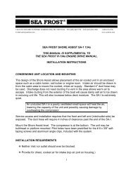
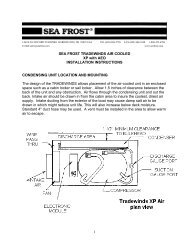
1. Locate the SEA FROST Receiver/Filter/Drier (RFD). The location of this part<br />
varies from boat to boat, but it is often found in the engine compartment, in a<br />
locker, or beneath the cabin sole. It is a blue metal can about 9 inches high and<br />
3 inches in diameter, with brass fittings connecting it to copper tubing. If you do<br />
not locate the RFD quickly, follow the route of refrigeration copper tubing, from<br />
the engine compartment to the icebox. Along the route you will find the RFD,<br />
along with other SEA FROST components. The RFD has a sight glass for<br />
viewing the flow of refrigerant.<br />
2. Start the boat's engine. Check to be sure the engine is pumping water.<br />
3. Locate the SEA FROST Control Panel. With the engine running at a fast idle (900<br />
to 1200 rpm), and while looking into the sight glass in the RFD, have a helper<br />
turn the Panel Timer knob past "10" to cock the switch and start the compressor.<br />
The engine should load, slowing slightly.<br />
4. MONITOR THE SIGHT GLASS CONTINUALLY. White FOAM should appear in<br />
the sight glass indicating that refrigerant is present. This foam may disappear<br />
quite quickly, but IF NO FOAM IS EVIDENT, that is, if the sight glass does not<br />
show presence white high speed foam within a minute of operation, the system is<br />
flat. DO NOT CONTINUE TO OPERATE THE SYSTEM. OPERATION IN THIS<br />
MODE WILL RUIN THE COMPRESSOR. Switch off the 12-volt panel breaker to<br />
prevent operation until the problem is corrected. CALL US AT 603-868-5720.<br />
2
5. If white foam is evident watch closely for a transition from foam to clear: a clear<br />
sight glass indicates a sufficiently charged system. This point can be missed if<br />
proper attention is not given. A FULL SIGHT GLASS AND AN EMPTY GLASS<br />
LOOK THE SAME! It is possible for the sight glass to show large, almost<br />
stationary bubbles even when the charge is sufficient, so it is important to<br />
differentiate between "foam" and larger bubbles. The foam condition has<br />
velocity and direction, but the larger bubbles are nearly stationary. If the<br />
foam does not clear, the system is low on charge. CALL US AT 603-868-5720 for<br />
trouble shooting and correction help.<br />
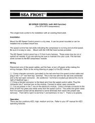
There are three conditions of charge indicated by the sight glass:<br />
• A black or clear glass and no cooling indicates no charge. Turn off the<br />
compressor at once.<br />
• A white foaming glass and some cooling indicates the system is undercharged<br />
or has lost charge. Refer to the manual regarding leak checking and adding<br />
charge.<br />
• A black glass and proper cooling indicates all is well.<br />
RFD SIGHT GLASS DETAIL<br />
EMPTY OR CLEAR STATIONARY BUBBLES FOAM/LOW<br />
6. Feel the SEA FROST Plate in the icebox five minutes after engaging the timer<br />
switch. If the sight glass clears yet the plate temperature does not drop after 5<br />
minutes of operation, turn off the system and CALL US AT 603-868-5720.<br />
7. If the proper charge is indicated, make ice and go sailing.<br />
Inspecting the sight glass periodically for several weeks after a new installation and<br />
every time after a lay period is assurance that your <strong>Sea</strong> <strong>Frost</strong> system is assembled<br />
properly and is a good maintenance habit.<br />
3
TABLE OF CONTENTS<br />
OPERATION 5<br />
GENERAL DESCRIPTION 5<br />
ICE MAKING 7<br />
MAINTENANCE 8<br />
ZINC, CONDENSER: SKETCH 9<br />
HOW REFRIGERATION WORKS 10<br />
INSTALLATION 11-30<br />
WORK HABITS 11<br />
TUBE HANDLING, CUTTING, BENDING 12<br />
COMPRESSOR, INSTALLATION 12-13<br />
PULLEY MOUNTING 14<br />
BELTS, COMPRESSOR 14<br />
CONDENSER 15<br />
BLOCK 16-17<br />
VALVE UNIT 17<br />
SWAGELOCK FITTINGS, MAKE-UP & RECONNECTING 19-20<br />
RECONNECTING PRE-SWAGG<strong>ED</strong> FITTINGS 21<br />
HOSE-TO-COMPRESSOR FITTINGS 22<br />
RUNNING THE LINES; RFD POSITIONING; INSULATING LINES 23-25<br />
RFD (RECEIVER FILTER DRYER) 25<br />
ELECTRICAL SYSTEM; WIRING; CONTROL PANEL; TIMER 26-27<br />
WIRING DIAGRAM 27<br />
ASSEMBLY INSPECTION CHECK LIST 28<br />
REFRIGERANT HANDLING 29<br />
ACCESS TO THE SYSTEM; SERVICE PORTS 30-31<br />
CAPPING A CAN OF REFRIGERANT 32<br />
CHARGE HOSE; VENTING THE CHARGE 32<br />
CHANGING CANS; GAUGES 32<br />
LEAK CHECKING 32-34<br />
NEW SYSTEM CHARGING 34-35<br />
READING THE SIGHT GLASS 35-36<br />
PROPER CHARGE AMOUNT: MAXIMUM CHARGE 36<br />
DISCHARGING THE SYSTEM 38<br />
TROUBLESHOOTING 39-40<br />
TROPICAL OPERATION MAINTENANCE 41<br />
PRESSURE CHARTS 43-45<br />
4
GENERAL DESCRIPTION<br />
The SEA FROST Engine Drive is a cold storage refrigeration system powered by the<br />
boat's engine. Cold storage is attained by rapidly freezing the solution contained in the<br />
plate, creating a captive (replenishable) block of ice. The system uses a compressor<br />
belt-driven by the boat's engine. The compressor has an electromagnetic clutch<br />
controlled by the timer switch on the SEA FROST control panel. Refrigerant from the<br />
compressor is piped to the SEA FROST plate in the icebox.<br />
BREAK IN PERIOD<br />
REFER TO THE START UP PROC<strong>ED</strong>URE IN THE BEGINNING OF THIS MANUAL.<br />
EVERY TIME THE SYSTEM IS RESTART<strong>ED</strong> FROM WARM, CHECK TO BE SURE IT IS<br />
COOLING BEFORE OPERATING THE COMPRESSOR EXTENSIVELY. THIS IS YOUR<br />
SYSTEM. SIMPLE OBSERVATIONS OF YOUR SYSTEM AND OPERATING CAUTION<br />
WILL PREVENT DAMAGE.<br />
OPERATION<br />
STEP 1.<br />
To operate the system, the engine must be running. This system is water-cooled and<br />
relies on water being pumped by the engine. Water flow is most important, therefore<br />
CHECK THE WATER FLOW FROM THE BOAT'S EXHAUST BEFORE OPERATION.<br />
STEP 2. THE TIMER CONTROL<br />
The system may be operated at any engine speed and is not affected by heel angle.<br />
When not under way, a fast idle will give good performance. TURN the control panel<br />
timer switch clockwise past "10" to cock the switch. From this "10" position, the switch<br />
may be overridden to "OFF" or advanced to the desired running time. The spring<br />
wound timer will turn off automatically. When the timer is started, the red lamp will go<br />
on and the engine should see a slight rpm drop (larger engines will be less affected).<br />
Within 5 minutes you will notice the plates getting cold.<br />
WARNING: After 5 minutes of operation, check for a drop in the plate temperature by<br />
feeling the plate with your hand. If no noticeable cooling has occurred, turn off the<br />
panel timer switch. Check the charge level (Checking the Refrigerant Charge) and<br />
check the water flow from the exhaust. TO PROTECT THE COMPRESSOR, DO NOT<br />
OPERATE the system if this temperature drop is not noted. CALL US AT 603-868-<br />
5720.<br />
5
After about one half hour, the plate will become very cold. The maximum cold storage<br />
is generally attained within an hour.<br />
Starting from warm will require more running than the normal refreezing time of the<br />
plate in its usable temperature range.<br />
The concept of the SEA FROST system is to create as much frozen material in the plate<br />
as fast as possible. This "coldness" then keeps the cabinet cold. Daily running times<br />
are based on the time needed to freeze enough of the plate to maintain proper cooling.<br />
The plate must be frozen. Chilling the plate without freezing it will not provide any<br />
holdover. You will learn about the daily time required for SEA FROST operation by<br />
using the system.<br />
Note: Maximum holdover time will be obtained when the cabinet and contents are at<br />
their lowest temperatures and the plate is frozen solid. There is no limit to "on" time<br />
however, no advantage is gained by running the system beyond this point and in<br />
refrigeration applications over running will freeze items. Experiment with two shorter<br />
periods a day over one long run once per day.<br />
Holdover time is effected by cabinet size, cabinet insulation, contents added to be<br />
cooled, cabinet opening and closing, and climate. Freezer systems will generally<br />
require operation twice a day.<br />
A SUGGESTION.<br />
As soon as the engine has stopped or the timer has run out, the plate will begin to warm<br />
up as it absorbs heat, cooling the icebox. You might decide that it is a good idea to run<br />
the unit in the last minutes of the day to provide ice for drinks. Short periods of<br />
operation whenever the engine is on for other purposes will be beneficial. Maximum<br />
storage will require that the plate be frozen. The plate may thaw and still not require<br />
running in refrigeration applications. Monitor the box temperature.<br />
Two shorter periods a day may be better than a long one once a day. When the<br />
holdover freezing is complete the benefit of running is only to delay warming. (There is<br />
some help in that cooling of the contents of the box will increase holdover time but heat<br />
("cold") moves slowly and it will be more efficient to wait and run again later.)<br />
Experimentation will provide the best instruction on how the SEA FROST should be<br />
operated on your boat.<br />
DEFROSTING will be required. A heavy layer of frost or ice will reduce cooling. This is<br />
very important in freezers. The plates may be defrosted by scraping the face with an<br />
ice scraper or spatula. Warm water may be used.<br />
6
ICE MAKING<br />
With the Block System or Flat Mounted Plates<br />
Making ice in plastic self-closing bags will prevent spilling and make large amounts of<br />
ice. A good method is to use a bag within a bag. Fill the inner bag with water, seal it,<br />
and dry off the outside surface. The outer bag should be wetted to freeze it to the<br />
Block. Because the Block freezes quickly, trays and bags hold fast. When the ice is<br />
ready, the inner bag may be easily removed. Hit the frozen bag with a winch handle to<br />
break it up.<br />
If the Block is well frosted, it may be necessary to allow the top surface of the Block to<br />
defrost before operating the system to make ice. If the Block is well frozen several<br />
batches of ice can be made without operating the compressor. By the same token ice<br />
making doesn't require compressor operation for the whole period ice is forming.<br />
With Vertical Trays (on Vertical Plate Systems)<br />
Fill the vertical trays with water and hang them on the stainless steel rod on the face of<br />
the plate. Try to get some water between the tray and the plate surface to increase the<br />
thermal contact to speed freezing.<br />
The trays may take time to freeze after the plate is frozen and the engine compressor<br />
has been switched off.<br />
Plan to wait for the trays to thaw in a sink or away from the plate in the refrigerator.<br />
When the outside surface is wet invert the tray and let the ice slide out.<br />
After ice has been made and harvested, store it in sealable plastic bags in the<br />
refrigerator or freezer. Leaving the ice in trays in contact with the plate will allow the ice<br />
to melt if the plate goes above freezing.<br />
7
MAINTENANCE<br />
Like your engine, your SEA FROST needs periodic checking.<br />
ROUTINELY CHECK:<br />
1. The refrigerant charge. (Checking the Refrigerant Charge) NEVER OPERATE<br />
SYSTEM WITHOUT PROPER CHARGE!<br />
2. Check belt tension and condition<br />
3. Periodically tighten compressor mounting bracket bolts.<br />
4. Check the condenser zinc. FAILURE TO MAINTAIN THE ZINC ANODE WILL<br />
CAUSE EXTENSIVE DAMAGE TO THE SYSTEM!<br />
5. Check all components, bilge and engine room fittings for corrosion and wear. BE<br />
SURE TO LOCATE AND INSPECT ALL FITTINGS AND COMPONENTS IN<br />
THE SYSTEM. KNOW THE LOCATION OF ALL CONNECTION POINTS.<br />
Spray with a rust inhibitor REGULARLY. Corrosion unchecked in the marine<br />
environment will severely reduce the life of your system.<br />
6. Winter storage will require that the water-cooled condenser be drained or flushed<br />
and filled with antifreeze solution to avoid freeze damage. If the condenser is to<br />
be left dry flushing with a large amount of fresh water to remove salt deposits is<br />
recommended.<br />
7. For tropical lay up, flush fresh water through the condenser.<br />
CLEANING<br />
The plate surface protects itself with a layer of oxidation. You might find after a long<br />
period of storage the plate will look chalky. This will not effect operation and is easily<br />
cleaned up with a pot scrubber and soap.<br />
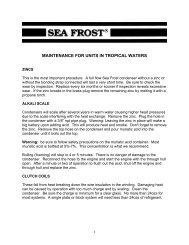
TROPICAL OPERATION MAINTENANCE<br />
A system that has operated in the tropics or is in service in the tropics may need to have<br />
the condenser cleaned with muriatic acid. Refer to the data sheet on page 47.<br />
8
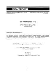
DETAIL OF CONDENSER ZINC ASSEMBLY<br />
To change the zinc, first close the engine<br />
seacock. Using a 7/16” and 11/16” openend<br />
wrenches, hold the brass plug and<br />
remove the outer nut. Carefully bend the<br />
ground strap away from the plug. Remove<br />
the plug. Water will drain from the<br />
condenser (or drain the condenser by<br />
removing a hose down stream.) Compare<br />
the old zinc to a new zinc. Using pliers hold<br />
the zinc and unscrew the plug. If the zinc<br />
breaks in the brass plug, heat the plug<br />
holder with a propane torch to melt the<br />
remaining zinc. Thread the new zinc into<br />
the plug. Snug with pliers making sure that<br />
the zinc is not cracked or stressed by over<br />
tightening. Use a pipe thread sealant on the<br />
plug thread. BE AWARE THAT THIS IS A<br />
TAPER<strong>ED</strong> PIPE THREAD. Thread the plug<br />
into the condenser housing about 3/4 of the<br />
length of the plug. This should seal the<br />
connection. EXCESSIVE TIGHTENING<br />
WILL CRACK THE CONDENSER<br />
HOUSING. Open the seacock and check<br />
for leaks. Reassemble the ground strap,<br />
and nut. NOTE: This is an electrical<br />
connection; the brass plug and the ground<br />
strap should be free of corrosion and<br />
oxidation. The final assembly should be<br />
sprayed corrosion block, T-9, or similar rust<br />
inhibitor.<br />
9
HOW REFRIGERATION WORKS<br />
There are two important concepts to understand in order to learn about refrigeration.<br />
They are latent heat and phase changes. A great deal of heat is required to change a<br />
solid to a liquid, and a liquid to a gas. A great deal of heat must be removed to reverse<br />
these changes. These changes are called phase changes, or changes of state. The<br />
heat removed or added at these phase changes has no effect on the temperature of the<br />
substances until the change is complete. For instance, ice melts at 32 degrees F.<br />
Water freezes at 32 degrees F. Ice and water will remain at 32 degrees F until the<br />
freezing or melting process is complete. Latent heat is this hidden energy required to<br />
make or break the bonds in a phase change.<br />
By evaporating liquid to a gas, we can absorb heat. By condensing a gas to a liquid, we<br />
give up heat. <strong>Refrigeration</strong> is the use of these phase changes to move heat out of the<br />
icebox (cooling it).<br />
We all know that cold is the absence of heat. A practical example of heat absorption by<br />
evaporation is rubbing alcohol evaporating in your hand and cools your hands. The<br />
alcohol is actually using the heat from your hand to boil. The absorption of heat cools<br />
your hand.<br />
Pressure affects the temperature at which a gas phase change will occur. Using water<br />
as an example, water boils at sea level at 212 F. On top of Mt. Everest it boils at a<br />
much lower temperature. The air pressure is lower allowing the water-to-steam phase<br />
change to occur more easily. A pressure cooker increases the pressure on water to<br />
restrict boiling to a higher temperature. A pressure cooker will cook food faster because<br />
the temperature is higher. Remember that a phase change involves latent heat. The<br />
temperature of boiling water is only 212 F at sea level. The evaporation action is<br />
absorbing heat at a rate equal to the rate of heat applied, preventing further temperature<br />
rise.<br />
R-<strong>134a</strong> will boil at minus 15 degrees F at sea level. By evaporating liquid R-<strong>134a</strong> in the<br />
SEA FROST plate, heat is absorbed making refrigerant vapor. To dispose of this heat,<br />
a condensing phase change is necessary. By increasing the pressure (compressing)<br />
we can raise the boiling point of the refrigerant vapor at the condenser. <strong>Sea</strong>water<br />
passing the condenser coils removes the heat, forcing the vapor to a liquid state again.<br />
Pressure, therefore, is the key that allows passing the heat we have taken from the<br />
icebox to a warmer place (the sea water) and converting the vapor to liquid to be reevaporated<br />
again. By causing R-<strong>134a</strong> to boil (evaporate) in the SEA FROST plate, we<br />
use the heat energy there. This activity cools the liquid solution within the plate,<br />
causing it to change phase (freezing to a solid). By freezing this solution, we have<br />
increased it's heat absorption capacity more than 100 times. When the cycle is stopped<br />
(the compressor is turned off) the frozen plate will begin to absorb the heat that leaks<br />
through the insulation in the icebox. The absorption will be at a constant temperature<br />
until the phase change to liquid (melting) is complete. This is the principle of holdover<br />
refrigeration and the function of your SEA FROST.<br />
10
INSTALLATION<br />
Work Habits<br />
Installer's care should be stressed. No matter how good SEA FROST equipment is, it's<br />
performance and life are in the hands of the installer. To insure your work:<br />
1. Read this manual.<br />
2. Reread any aspect you don't understand.<br />
3. Follow Swagelok instructions carefully.<br />
4. Install the RFD last and the same day the system is charged.<br />
5. Spend enough time leak-checking to be sure there are no leaks.<br />
6. Thanks from all of us who have to guarantee your work.<br />
Two contaminants will give you problems in a refrigeration system. They are WATER<br />
and DIRT. Moisture in the air is always present and cannot be eliminated; water in this<br />
case refers to puddles and drops. Dirt is any solid. The installer's habits are important<br />
in ensuring a trouble-free start-up. We have added a large receiver filter drier (RFD) to<br />
take care of all dirt and moisture that might get into the system during a careful<br />
installation. Moisture in the system is boiled off when the system is evacuated, or it is<br />
captured in the desiccant. There is a screen in the expansion valve to prevent dirt from<br />
plugging it.<br />
Excess moisture that the RFD can't handle will plug the expansion valve with ice. This<br />
ice stops the cycle. The only cure is to discharge the refrigerant, replace the RFD, reevacuate<br />
the system, and recharge it. This remedy takes time and is somewhat costly.<br />
Keep the system clean and dry!<br />
Tube Handling<br />
Installation is quite simple. All the copper tube comes to you with the ends capped.<br />
Any routing of the tubing must be done with the tube either taped or capped. Cap both<br />
tube ends after each cut. Work with only one line at a time, and uncap only one end at<br />
a time.<br />
Tube Cutting<br />
Use only a tube cutter; hacksawing or any other method will introduce chips to the<br />
system and also distort the tube, making connections difficult and leak-prone. A<br />
miniature cutter is essential for this work. CUT SLOWLY to avoid a ridge on the inside<br />
of the tube. We do not recommend reaming or dressing the cut, as it is very easy to get<br />
chips of copper in the system that will cause trouble.<br />
11
Tube Bending<br />
Make all but the long sweep bends with a spring or lever bender; one kink and the line<br />
must be re-run. Don't add any more fittings than are absolutely necessary. Route all<br />
the lines in such a way that they are most direct but out of the way. Always leave<br />
several inches of straight undistorted tubing leading to all Swagelok fittings to allow<br />
proper connection. Again, keep everything sealed until you are ready to make that<br />
connection.<br />
FIT RFD LAST<br />
The RFD (receiver, filter, drier) should be the last component to be unpacked and fitted.<br />
The day the system is charged.<br />
THE COMPRESSOR<br />
The compressor is the first component to mount when installing the SEA FROST<br />
system.<br />
FITTING THE COMPRESSOR TO THE BASE BRACKET<br />
WARNING: FAILURE TO FOLLOW THESE DIRECTIONS WILL CAUSE<br />
IRREPARABLE DAMAGE TO THE COMPRESSOR AND VOID ANY CLAIMS.<br />
12
The compressor base bracket may need to be lightly filed or sanded to properly fit<br />
between the mounting "ears" of the compressor. It must be a perfect fit with no force<br />
required to slide the bracket onto the compressor and yet have zero clearance<br />
between the two parts. Forcing the compressor on to the bracket will spread the ears<br />
cracking the compressor case. Extra space will allow the hinge bolt to work and if<br />
tightened break the compressor ears.<br />
If you are using an available SEA FROST engine bracket kit follow the mounting<br />
instructions included with it. The "Compressor Posture", "Low Head" option and "Fitting<br />
the Compressor to the Compressor Base" must be followed.<br />
In determining the compressor location for custom brackets and off engine mounting of<br />
the compressor consider all of the following:<br />
COMPRESSOR POSTURE<br />
When mounted, the compressor must not lay over more than 45 degrees from<br />
vertical. The port fittings, the clutch coil wire, and the ground screw indicate the top of<br />
the compressor.<br />
Allow clearance for the compressor hoses and belt adjustment if the compressor is<br />
mounted under the engine.<br />
An optional low profile head is available that requires no top clearance and allows the<br />
hoses to exit straight back. Hoses can be ordered with straight fittings.<br />
We recommend that the compressor be driven by its own belt.<br />
A single hi-power "A" belt is all that is required to drive the compressor<br />
The compressor should be driven by a pulley five inches in diameter. The<br />
compressor speed ratio should not exceed the crankshaft speed of the engine. This<br />
ratio will give proper cooling at a fast idle and also allow operation at cruising RPM's.<br />
The compressor will draw up to two horsepower. It should be ruggedly bolted.<br />
The extra pulley on the compressor may be used to drive a pump or alternator.<br />
The compressor may be mounted to a fabricated bracket that is bolted to the engine.<br />
A jackshaft may be used to drive the compressor.<br />
The compressor may rotate in either direction.<br />
13
OFF-ENGINE COMPRESSOR MOUNTING<br />
Engine motion is a torsional load, concentric around the crankshaft. At the crankshaft<br />
center, the engine is stationary which allows off-engine mounting of the compressor.<br />
Side loads on the clutch pulley do not affect the compressor since the construction of<br />
the free wheel pulley puts all loads on the compressor case. This protects the<br />
compressor bearing and shaft seal from failure and leaks from side load. The<br />
compressor is a very smooth device and may be hard mounted on the engine beds or<br />
other structural members attached to the hull. It will not introduce any vibration or noise<br />
by this mounting, and in many cases a much stronger mount is possible. The drive belt<br />
will not transmit any engine vibration to the boat. The compressor pulley and the engine<br />
drive pulley are large and will provide plenty of belt contact without excessive tightening,<br />
so off-mounting will not "ground-out" a flex mounted engine.<br />
PULLEY MOUNTING ON ENGINES<br />
IT IS IMPERATIVE THAT THE EXTRA PULLEY BE MOUNT<strong>ED</strong> TO THE ENGINE<br />
CRANK PULLEY USING LOCK WASHERS OR THREAD LOCK ADHESIVE /<br />
SEALANT.<br />
FAILURE TO LOCK ATTACHMENT BOLTS WILL ALLOW THE BOLTS TO LOOSEN,<br />
CAUSING DAMAGE AND POSSIBLE DANGER FROM FLYING PARTS.<br />
BOLTS SHOULD BE TIGHTEN<strong>ED</strong> TO A TORQUE SETTING RECOMMEND<strong>ED</strong> FOR<br />
THE DIAMETER AND GRADE OF BOLT BEING US<strong>ED</strong>.<br />
Recommended adhesive/sealant: Loctite 271 by Loctite corporation of Newington, CT.<br />
and Cleveland, OH.<br />
COMPRESSOR BELTS<br />
Various belts are available with an "A" section (1/2"). Specify a high power belt.<br />
Fractional horsepower belts will stretch and wear rapidly. Cogged belts and Kevlar<br />
strand reinforced belts are available but not essential.<br />
Belt length is measured on the back edge of a belt. An easy way to get a belt size is to<br />
wrap masking tape around the pulleys with the compressor in the loose position. Break<br />
the tape in one place and peel it off. Measure the tape to get the belt length. When the<br />
belt size is determined record the brand and part number. Each belt manufacture has a<br />
different sizing.<br />
14
CONDENSER<br />
The condenser should be connected into<br />
the raw water line to the engine after the<br />
in-line strainer.<br />
The SEA FROST condenser will not<br />
restrict water flow to the engine, but be<br />
certain to avoid restrictions in the water line<br />
by ensuring sufficient hose ID from the<br />
through hull to engine.<br />
It may be connected on the discharge<br />
side of the engine's raw water pump, be<br />
certain it receives the full flow of the coldest<br />
water.<br />
It MUST be mounted vertically: the zinc<br />
element is at the bottom<br />
ZINC SERVICE ACCESS<br />
The zinc anode must be accessible as periodic checking is required. For best service<br />
access to the zinc, mount the condenser with the zinc away from the bulkhead. There<br />
is an alternate zinc location on the bottom. Swap locations of the plastic plug and the<br />
zinc plug. Use pipe thread sealant on the threads. Tighten carefully. (See page 9)<br />
Water must enter the bottom of the condenser and exit the top.<br />
Be sure water fittings are tight. A leaky water fitting may prevent engine pump<br />
priming by leaking air into the circuit especially if the condenser is installed above the<br />
water line.<br />
15
BLOCK<br />
The SEA FROST block is 6 1/4" x 9" x 13 3/4" (excluding the mounting tabs). It must<br />
be solidly fixed within the icebox. It should be mounted high in the box to take<br />
advantage of natural convection.<br />
Leave 2" clearance (more is better) between the inside top of the box and the top of<br />
the block for ice making.<br />
The block copper tubing should exit the icebox wall to a place where the Valve Unit<br />
(V/U) can be fitted, such as a hanging locker, sail locker, or the engine compartment.<br />
This provides the cleanest easiest installation. There is some moisture created by the<br />
V/U if it is not properly insulated so accessibility for insulation application must be<br />
considered. However, if the icebox location is such that the V/U cannot be mounted<br />
outside, it is acceptable to install it on the inside of the box. The V/U operation is not<br />
effected by its temperature.<br />
The block must be installed in the horizontal mode.<br />
The mounting tab has been drilled and countersunk for 1/4" fasteners. The tab may<br />
be drilled out for larger fasteners. Through bolting with a large backing plate of plywood<br />
or to an existing bulkhead will distribute the load and provide a good mount.<br />
Support may be provided by a cleat or shelf. Shelving around the block may be used<br />
as a cold zone. However, keep in mind that air flow is required to cool all sections of<br />
the box, so don't restrict airflow with excessive shelving.<br />
A drilling template should be made. Drill 1-1/4" holes for the refrigerant tubes<br />
completely through the icebox wall if the V/U is externally fitted. This allows recesses<br />
for the white nylon bulkhead fittings on the block, and also facilitates removal of the<br />
block without having to ruin the connection tubes by cutting the Swagelok nuts and<br />
ferrules off, allowing clearance for the swage attached nuts. The larger holes also allow<br />
adding a moisture seal to any wooden bulkhead that has been drilled by filling the holes<br />
with the spray foam provided.<br />
Note: The fittings on the back of the block are not connection points: there are no<br />
internal joints in this system. Therefore field repairs cannot be made if the copper tubes<br />
are damaged or cut too short.<br />
16
PLATES<br />
SEA FROST holdover plates mount with<br />
a "Wellnut" expandable neoprene blind<br />
hole fastener. See the instruction tag<br />
packed with the plate. A template or the<br />
part itself should be used to locate the<br />
mounting holes. Drill 1/4" pilot holes then<br />
increase them to 1/2". Install the screw into<br />
the mounting tab then screw the mount onto<br />
the screw. Install the plate pushing the<br />
rubber mounts into the pre-drilled holes.<br />
Tighten the screws.<br />
PLATE LOCATION<br />
The plate size, location, and plumbing are designed for each application. This<br />
additional information is provided with each individual system.<br />
VALVE UNIT V/U<br />
For appearance and convenience of installation, the valve unit may be mounted<br />
outside the icebox. In certain applications and multiple plate systems it may be best to<br />
mount it inside. Location of the V/U in multiple plate systems is indicated in the design<br />
layout from our application engineer.<br />
On an externally mounted V/U two 1/2" Swagelok fittings fasten the V/U to tubing<br />
protruding through the icebox wall. Before cutting the tubing:<br />
1. Leave a minimum of 1 1/4" of tube beyond the bulkhead.<br />
2. Allow room for wrench access.<br />
On any installation:<br />
The Valve Unit may be mounted in any position.<br />
90-degree elbows can be factory installed on the Valve Unit to reduce the space<br />
requirements if necessary.<br />
The tubing will support the Valve Unit.<br />
The tubing must bottom in the fitting. A pencil mark 1" from the tube end should be<br />
flush with the fitting nut face when the tube is seated in the fitting.<br />
17
The V/U will attract moisture. If it is mounted externally to the cabinet be sure it is<br />
accessible for proper insulation installation after the system has been leak checked and<br />
operationally tested.<br />
For final installation the V/U see the Swagelok text.<br />
SUCTION PRESSURE UNIT ~ S/P/U<br />
The S/P/U is an epoxy cast rectangular block measuring 4" X 5 1/2" and 2" thick. This<br />
part contains the system access ports for charging and servicing the system. The<br />
access ports are located between the tube connection fittings. The tube connections<br />
are 1/2" and 1/4".<br />
The S/P/U is connected into the 1/2" tubing 1' to 4' from the compressor suction hose<br />
end. The 1/4" line from the RFD connects to the S/P/U. Then continues to the V/U.<br />
(See the drawing on page 24.)<br />
The S/P/U may be positioned as is convenient (sideways, upside down, vertical,<br />
horizontal.) The tubing has no directional requirement (input on left side or right side.)<br />
When mounting the S/P/U, position the insulation foam wrap behind it first. This<br />
insulation will then be wrapped around the section nearest the 1/2" tubing to prevent<br />
sweating.<br />
INSTALLATION RULES FOR THE S/P/U<br />
The S/P/U must be connected 1 to 4 feet from the suction hose end. (Extending this<br />
distance may reduce the performance of the system.)<br />
The tubing connected to the S/P/U must<br />
be routed allowing room for the 134-A<br />
service valves to connect to the ports<br />
between the tube connectors. The service<br />
valves will require 4" of clear space on<br />
each end of the S/P/U.<br />
The S/P/U must be insulated to prevent<br />
unwanted moisture from collecting and<br />
dripping.<br />
18
NOTES ON SWAGELOK FITTINGS<br />
Swagelok fittings come to you completely assembled, finger-tight. (Pieces a,b, and c in<br />
Drawing #1 are already together). They are ready for immediate use.<br />
Disassembly before use can result in dirt and foreign material getting into the fitting and<br />
causing leaks and you also risk damaging the threads if nuts are removed. If<br />
disassembly is necessary, reassemble per drawing.<br />
This is a double ferrule system. The most serious installation problem encountered with<br />
SEA FROST is the improper assembly of these fittings. Be absolutely sure that you<br />
assemble all fittings as in Drawing #1.<br />
To ease assembly slacken the fitting nut slightly before assembly. Then retighten with<br />
fingers before tightening with a wrench. (This is to avoid cross threading.)<br />
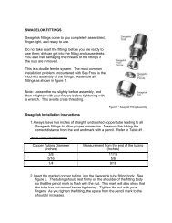
Step 1. Always leave two inches of straight, undistorted tubing leading to all Swagelok<br />
fittings to allow proper connection.<br />
Step 2. Prior to inserting 1/2" tubing into the Swagelok tube fitting, make a pencil mark<br />
1" from end of tube. Prior to inserting 3/8" tubing, make a pencil mark 3/4" from the end<br />
of the tube. With 1/4" tubing make a mark 5/8" from the end.<br />
Step 3. Insert clean, smooth tubing with the pencil mark into the Swagelok tube fitting.<br />
You can be sure the tube is resting firmly on the shoulder of the fitting when the pencil<br />
mark is flush with the nut. This mark will also indicate that the tube has not moved<br />
before tightening. (As the fitting is tightened the space from the pencil mark to the<br />
shoulder will increase.)<br />
Step 4. Tighten the Swagelok nut to a wrench snug* position. Scribe the nut with a<br />
pencil at the 6:00 o'clock position (see drawing #1, step # 2).<br />
* Wrench snug is the first point in the assembly tightening when the tube cannot be<br />
pulled from the fitting, (i.e. when the ferrules tighten enough to contact the tubing).<br />
Step 5. Now, while holding the fitting body with a back-up wrench, tighten the nut oneand-one-quarter<br />
turns ( 1-1/4). To do so, watch the scribe mark, make one complete<br />
revolution, and continue to the 9:00 o'clock position. (See drawing #1, step #3).<br />
19
DRAWING 1<br />
STEP 1<br />
Simply insert the tubing into the<br />
SWAGELOK tube fitting. Make sure that<br />
the tubing rest firmly on the shoulder of<br />
the fitting and that the nut is wrench<br />
snug.<br />
STEP 2<br />
Before tightening the SWAGELOK nut,<br />
scribe the nut at the six o'clock position.<br />
STEP 3<br />
Now, while holding the fitting body steady<br />
with a backup wrench, tighten the nut 1 1/4<br />
turns. Watch the scribe mark, make one<br />
complete revolution and continue to the 9<br />
o'clock position. By scribing the nut at the 6<br />
o'clock position as it appears to you, there<br />
will be no doubt as to the starting position.<br />
When tightened 1 1/4 turns to the 9 o'clock<br />
position you can easily see that the fitting<br />
has been properly installed.<br />
20
SWAGELOK FITTINGS ARE TO BE TIGHTEN<strong>ED</strong> TO A TORQUE SPEC, NOT INFINITE<br />
TIGHTNESS. BE SURE YOUR STARTING POINT IS WRENCH SNUG. A DISTORT<strong>ED</strong><br />
TUBE MIGHT GIVE A FALSE STARTING POINT.<br />
* When making all connections, USE TWO WRENCHES. Don't allow the fittings to turn<br />
or twist when tightening.<br />
RECONNECTING PRE-SWAG<strong>ED</strong> FITTINGS<br />
Connections can be disconnected and retightened many times.<br />
When reconnecting, insert the tubing with pre-swaged ferrules into the fitting until the<br />
front ferrule seats in the fitting. Tighten the nut by hand. After tightening to wrench<br />
snug, rotate the nut about one-quarter turn with a wrench.<br />
SWAGELOK PERFORMANCE<br />
Swagelok fittings have built-in spring interaction between the ferrules. This<br />
compensates for temperature changes and allows the fittings to be reconnected many<br />
times. As the fitting is tightened, a burnishing occurs between the body of the fitting and<br />
the ferrules and between the ferrules and the tube. This action provides the tightest<br />
connection available.<br />
21
HOSE TO COMPRESSOR FITTINGS<br />
REMOVE THE PLASTIC CAPS FROM COMPRESSOR PORTS.<br />
To install a tube "O" ring fitting on the compressor, inspect the hose ends to be sure<br />
they are clean and free from burrs. Apply a drop of oil to the backside of the nut. This<br />
will lubricate the nut to allow proper tightening. Install the proper "O" ring on the hose<br />
fitting. Uncap the compressor port, removing the nylon cap and rubber insert plug.<br />
Insert the correct fitting in the compressor port. Tighten the nut wrench snug. Using a<br />
back up wrench on the compressor port, tighten one quarter of a turn more. This fitting<br />
should feel tighter than a SWAGELOK. The elbow should not rotate when tightening is<br />
complete.<br />
22
RUNNING THE LINES<br />
See the schematic diagram. Prior to making up connections see "Swagelok Fittings"<br />
and "Hose-to-compressor Fittings" texts.<br />
PLANNING<br />
1) The hose assemblies connecting the compressor to the copper tubing allow for<br />
movement of the compressor after installation to enable work on and around the engine<br />
with out having to disconnect the system. Leave some slack in the hoses and have<br />
both hoses directed the same way to allow compressor movement as necessary for<br />
access to anticipated repair areas. Hoses without adequate slack will cause failure of<br />
the fittings from engine vibration.<br />
2) Keep tube runs as short as possible. The suction (return) line should be as direct as<br />
possible with a minimum number of bends.<br />
3) THE RFD IS FITT<strong>ED</strong> WITH A SIGHT GLASS. THIS GLASS MUST BE VISABLE<br />
FOR CHARGING AND SERVICING THE SYSTEM. It can be viewed from the top at up<br />
to a 45-degree angle but not from the bottom or side. (A mirror installed above the<br />
glass is one way of saving a poorly planned installation. Avoid this if possible.) Be sure<br />
the sight glass is easily visible!<br />
Observe the inlet/outlet on RFD when mounting it. The glass is offset toward the outlet.<br />
The 3/8" (larger) connector accepts the line from the condenser. The 1/4" (smaller)<br />
fitting connects to the line leading to the S/P/U. The RFD should be unpacked and<br />
installed only after all the lines are run and all other fittings are made.<br />
23
4) Helpful tools.<br />
Coil spring-type tube benders are available for 3/8"-1/2" O.D. tube. These springs are<br />
slid over the tube. The bend is formed in the spring then the spring is removed by<br />
unscrewing.<br />
Mini tube cutter: "IMP" by Gould Imperial requires less than 1 1/2" radius clearance<br />
for the cut. This is essential to trim the block or plate tubing.<br />
LINE CONNECTION PLAN<br />
The compressor hose with the smaller elbow fitting, attaches to the discharge side of<br />
the compressor. The other end of the hose has a 3/8" Swagelok fitting. A 3/8" tube<br />
goes from the hose to the top of the condenser. From the bottom of the condenser, 3/8"<br />
tube runs to the RFD. From the RFD, 1/4" tube goes to the Suction Pressure Unit<br />
(S/P/U). From the S/P/U, 1/4" tube connects to the V/U. The return line from the V/U is<br />
1/2" tube to the S/P/U. From the S/P/U, 1/2" tube returns to the Swagelok-to-hose<br />
fitting. The compressor hose then returns to the compressor.<br />
NOTE: It is best to install the S/P/U in the direct line of the 1/2" tube path. The 1/4"<br />
liquid line path is easily doubled back through the S/P/U on its way from the RFD to the<br />
V/U.<br />
RFD (Receiver Filter Drier)<br />
DO NOT OPEN THE RFD UNTIL ALL THE OTHER CONNECTIONS HAVE BEEN<br />
MADE AND YOU ARE READY TO COMMISSION THE SYSTEM.<br />
Because the RFD contains desiccant to absorb moisture<br />
and the absorption is limited, it is important to unpack<br />
and install it after all other connections are made.<br />
Leaving the RFD installed on a partially open system<br />
may reduce its capacity by allowing it to absorb moisture<br />
in free air before the system is sealed.<br />
The RFD is a reservoir for excess refrigerant. The RFD<br />
also contains a sight glass in the top. (Please refer to the<br />
planning section regarding location and "readability" of<br />
the sight glass) A pick-up tube extends from the bottom<br />
of the canister to the outlet. For proper function of the<br />
reservoir, the RFD must be VERTICAL to ensure proper<br />
operation at various heel angles.<br />
24
MOUNTING THE RFD<br />
The inlet is 3/8" from the condenser and the 1/4" connection is toward the S/P/U. The<br />
sight glass is offset on the RFD toward the outlet. The RFD is mounted using the<br />
smaller plastic bracket and a plastic tie wrap. Tie wraps with screws should be used to<br />
support the tubes.<br />
INSULATING THE LINES<br />
Insulating should be the last step after leak testing because it will cover fittings that must<br />
be leak-checked. On long uninterrupted lengths of tubing the insulation can be slipped<br />
over the tube before attaching Swagelok fittings. Insulation should be installed only on<br />
dry lines, and only after spraying with Krylon clear coat.<br />
The suction return line is cold and will attract moisture (as frost) when running. The<br />
suction return line includes all the exposed 1/2" tubing and the larger fittings. The entire<br />
V/U will also frost as well as the section of the S/P/U connected to 1/2" tubing. It is<br />
important to insulate the 1/2" line, the V/U, SPU, and all the fittings along the line to<br />
prevent moisture from gathering.<br />
INSTALL THE INSULATION IN A MANNER THAT WILL NOT TRAP WATER AROUND<br />
A LOW POINT. Trapping salty bilge water in the insulation will reduce the operating life<br />
of tubing and fittings. If the insulation is split and wrapped over the tube, install it with<br />
the split side down.<br />
Tubing within the icebox need not be insulated.<br />
Closed cell foam is provided to insert the tube into, or to split and wrap onto the tubes<br />
that are impossible to feed into the insulation. The foam wrap should be taped with<br />
vinyl electrician's tape<br />
TIE WRAPS<br />
Tie wraps should be used to support the wiring, tubing, and insulation. There is a screw<br />
hole in the end of each wrap that is used for mounting. Loosely loop the wrap, mount<br />
the screw loosely, snug the wrap, tighten the screw, and trim the excess. Be sure not<br />
to leave a sharp edge that might cut someone.<br />
25
ELECTRICAL SYSTEM<br />
The electrical system for the SEA FROST system includes a Control Panel comprised<br />
of a timer switch, pilot light, circuit breaker, and a high pressure cutout switch in the<br />
S/P/U.<br />
CONTROL PANEL LOCATION<br />
In choosing a location for the control panel, find the best location within the cabin<br />
nearest the cockpit and engine controls. The panel is not waterproof. The system may<br />
want to be activated whenever the engine is run.<br />
OPERATION<br />
With 12 volts DC available to the panel, turning the timer clockwise will engage the<br />
compressor clutch, indicated by the pilot light. The unit can be shut off by turning the<br />
timer to "O" or shutting off the 12-volt supply. In the latter case, the timer will run down<br />
by itself. If the system is turned on when the engine is off, the compressor clutch will<br />
engage, but no cooling will take place. The light will come on, and normal operating<br />
current will be drawn from the battery.<br />
AMPERAGE DRAW<br />
The compressor clutch will draw 3 to 3.5 amps per hour at 12 volts when the timer is<br />
operated. (A 24-volt system will draw 1.5 to 1.75 amps per hour.) The timer panel<br />
breaker is rated at 7 amps and the wire is rated to about 20 amps. The supply to the<br />
timer should have at least a ten-amp breaker.<br />
Because the compressor is switched on only when the engine is on, no power is<br />
consumed from the batteries.<br />
TIMER<br />
The timer is a spring wound device that must be "cocked" in order for it to disconnect<br />
when it returns to the "off" position. For this reason, it is necessary to turn it clockwise<br />
past "10". After the timer is cocked, it may be set to any time reading and may be<br />
manually overridden to "off".<br />
26
WIRING<br />
The electrical system is shown in the diagram. The red wire is connected to a source of<br />
12 volts DC and should be protected by a fuse or breaker of 10 to 15 amps. The blue<br />
wire is the power to the compressor clutch, and is connected to the black wire on the<br />
compressor with a butt connector. The brown wires are connected to the S/P/U by<br />
using crimp type insulated female connectors. Connect the white wire to the phillips<br />
head screw on the compressor (adjacent to the black feed wire) along with the 3 ft.<br />
white wire in the kit. This 3 ft. white wire is run to the engine block and is connected to<br />
a suitable bolt using the 3/8" ring terminal provided. All wires should be routed after the<br />
panel is installed and supported every 18" (minimum). Leave enough slack in the wire<br />
behind the panel to allow removal of the panel for service. Wires may be tied into<br />
existing wire ways. Cut off any excess wire before making the connector.<br />
27
DISPLACING OIL IN NEWLY INSTALL<strong>ED</strong> COMPRESSOR<br />
The compressor is shipped with the proper amount of oil for the system. THE OIL MUST<br />
BE DISPLAC<strong>ED</strong> FROM THE CYLINDERS BEFORE THE COMPRESSOR MAY BE<br />
TURN<strong>ED</strong> BY THE BOAT’S ENGINE. After completing all the connections, turn the outer<br />
face of the compressor drive disk at least five turns by hand.<br />
ASSEMBLY INSPECTION CHECK LIST<br />
[ ] 1. Check the lines to be sure they are properly routed. Check to see that the<br />
compressor discharge connects to the top of the condenser and the water line<br />
enters the bottom.<br />
[ ] 2. Check that the RFD sight glass can be seen.<br />
[ ] 3. Check all the connections with wrenches to be sure they have been made up.<br />
Refresh your knowledge by re-reading the Swagelok instructions.<br />
[ ] 4. Check the pulley and compressor bolts for tightness.<br />
[ ] 5. Check to make sure the compressor is mounted in an upright position.<br />
[ ] 6. Check the panel wiring by engaging the timer switch. The pilot lamp should<br />
come on, and compressor clutch should click.<br />
[ ] 7. Check the neatness of the installation, sufficient service access, secure wiring,<br />
tubing, and hoses supported to prevent damage and chafing.<br />
[ ] 8. Check the condenser zinc access to see that it is serviceable.<br />
[ ] 9. Check the service access of the S/P/U. The service access ports must allow<br />
attachment of the connecting valves.<br />
[ ] 10. Check (after leak checking and testing) that the system is properly insulated.<br />
28
REFRIGERANT HANDLING AND SAFETY<br />
Do Not proceed with any aspect you do not fully understand know what results to<br />
expect. Understand that pressure exists in refrigeration systems. Be careful.<br />
GENERAL SAFETY THIS IS IMPORTANT. READ THIS!<br />
R-<strong>134a</strong> is safe if handled properly. Avoid breathing vapors and prolonged skin exposure.<br />
Avoid using in areas of open flames. The vapor is heavier than air and may reduce<br />
oxygen available for breathing. Use with sufficient ventilation to keep exposure below<br />
recommended limits. Do not mix with air for leak testing or use with air for any<br />
purpose above atmospheric pressure. Liquid R-<strong>134a</strong> will freeze the skin. It’s especially<br />
dangerous to the irreparable tissues of the eyes.<br />
Do not pressurize an empty system with R-<strong>134a</strong> without first evacuating the<br />
system with a vacuum pump.<br />
NEVER operate a system with the high side (discharge) open to the refrigerant supply.<br />
Pressurization of the refrigerant container could cause it to burst.<br />
WARNING. When charging or working on the system with the engine running, watch<br />
for MOVING BELTS AND PULLEYS. Loose clothes and long hair can pull you into a<br />
belt. PLEASE BE CAREFUL.<br />
NEVER connect or disconnect gauges to a system while the compressor is operating<br />
PROC<strong>ED</strong>URES FOR WORKING WITH R-<strong>134a</strong><br />
1) A new uncharged system must be evacuated before adding R-<strong>134a</strong>.<br />
2) An R-<strong>134a</strong> system must only be pressurized with R-<strong>134a</strong> or nitrogen.<br />
3) Only service tools dedicated to R-<strong>134a</strong> are to be used. No parts, tubing, fittings,<br />
receivers, dryers, service gauges, or any refrigerant carrying components may be fitted<br />
to a R-<strong>134a</strong> system from a used system or from a CFC based system. Damage caused<br />
by the use of parts not supplied by <strong>Sea</strong> <strong>Frost</strong> for a R-<strong>134a</strong> system will cancel all claims<br />
against <strong>Sea</strong> <strong>Frost</strong>.<br />
4) No oil is to be added to the engine drive system but the PAG oil supplied by <strong>Sea</strong><br />
<strong>Frost</strong>, labeled and capped for engine drive use. No oil is to be added to a system<br />
with out prior consultation with <strong>Sea</strong> <strong>Frost</strong>.<br />
5) The oils used in R-<strong>134a</strong> systems are extremely moisture sensitive (hydroscopic). Do<br />
not leave any tube end or component connection open to air while assembling the<br />
system. Be sure to use only new, capped copper tubing and be sure to cap the copper<br />
coil after cutting it.<br />
29
ACCESS TO THE SYSTEM ~ SERVICE ACCESS PORTS<br />
The access ports are two small-capped valves on the S/P/U. The ports are labeled<br />
"Discharge" and "Suction". These ports are the service access to the system. To<br />
access these ports the proper connecting valve must be used.<br />
Be sure the plastic port caps are installed tightly after charging or service. The<br />
caps are to seal the ports. Without the caps the ports may leak.<br />
NOTE: THIS SYSTEM IS CHARG<strong>ED</strong> WITH R-<strong>134a</strong>. IT MUST BE CHARG<strong>ED</strong> WITH<br />
R-<strong>134a</strong> ONLY. ONLY D<strong>ED</strong>ICAT<strong>ED</strong> R-<strong>134a</strong> GAUGES AND EQUIPMENT ARE TO BE<br />
US<strong>ED</strong>. ANY CONTAMINATION FROM CFC BAS<strong>ED</strong> REFRIGERANTS WILL<br />
DESTROY THIS SYSTEM.<br />
GAUGES<br />
Gauges must be used in the evacuation and charging. They will provide information on<br />
the operation of the system when troubleshooting.<br />
A gauge sets consist of two gauges installed in a manifold with two hand wheel valves<br />
and hoses to connect the gauges to the system. The left gauge (blue) is a compound<br />
device; it indicates pressure and also vacuum. The right gauge (red) indicates pressure<br />
only. The hand wheels open a center port (yellow) to the left or right side respectively.<br />
Operation of the hand wheels is only necessary when moving refrigerant or evacuating.<br />
With the hand wheels closed, the gauges read the pressures of the connection points.<br />
At the end of the red and blue service hoses are R-<strong>134a</strong> connecting valves.<br />
30
R-<strong>134a</strong> SERVICE CONNECTING VALVES<br />
The R-<strong>134a</strong> connecting valves on the gauge hose ends are quick connect fittings with a<br />
specially designed valve that when turned opens and closes the hose end while<br />
opening the access service port.<br />
CONNECTING GAUGES TO AN UNCHARG<strong>ED</strong> SYSTEM<br />
To connect the connecting valves to the access service ports, remove the protective<br />
sealing caps from the S/P/U. Note that the ports are of different sizes. The larger<br />
diameter port is the discharge side and the smaller port is the suction side. Pull back<br />
the collar on the connecting valve and push it over the appropriate access port. Turn<br />
the connecting valve clockwise to open. It is important to open each connecting valve<br />
carefully. Do not force valve or turn it to it’s stop. Forcing the connecting valve will<br />
bend the service port core valve causing a leak. During the service operation these<br />
valves are left open. Control of refrigerant and vacuum is by the manifold hand wheels.<br />
TO INSTALL GAUGES ON A CHARG<strong>ED</strong> SYSTEM, with the system off, attach the<br />
connecting valves to the S/P/U. Proceed to "Venting the Gauge Set".<br />
VENTING THE GAUGE SET<br />
If the gauge set is not fitted with sealing valves or has not been purged with refrigerant,<br />
vent the hoses at the manifold body by opening the hand wheels to an open center<br />
hose for a few seconds allowing some of the system refrigerant to purge the hoses of<br />
air.<br />
DISCONNECTING GAUGES<br />
Disconnecting the gauge set after running the system may be done by turning off<br />
the discharge connecting valve first. Remove the connecting valve and re-cap the port<br />
on the S/P/U. Turn off the refrigerant supply. Both hand wheels on the manifold set<br />
may be opened and the compressor operated to extract the refrigerant from the<br />
manifolds. When the pressure in both gauges drops to the low side operating pressure<br />
turn off the hand wheels and the connecting valve. Turn off the compressor. Remove<br />
the remaining connecting valve and re-cap the access port.<br />
Disconnecting the gauge set on a static system may be done by turning off the<br />
connecting valves and disconnecting them from the access ports on the S/P/U. Re-cap<br />
the access ports.<br />
Refer to the gauge drawing on page 32.<br />
Adding charge to a working system should be done through the suction side (blue).<br />
31
(See Safety) The center hose is connected to the can tap. Be sure to vent the hoses to<br />
displace any air that might be in them. Keep your gauges clean. Inspect the rubber<br />
gaskets and "o" rings on the hose ends. Leak-check the gauge valve packing and all<br />
hose connections. Check and reset the "O" on the low side gauge to atmospheric<br />
pressure, if necessary.<br />
TAPPING A CAN OF REFRIGERANT<br />
Be sure the can of R-<strong>134a</strong> is clean and dry. Any contaminants on the top of the can or<br />
in the hose will enter the system. Turn the can tap valve counterclockwise to retract the<br />
piercing point, then thread the valve body onto the can. Be certain that the gasket is<br />
present and is smooth and elastic. With the can upright, screw the valve until the point<br />
pierces the can and the rubber gasket has sealed. The can is now tapped. The<br />
refrigerant flow is now regulated with the can tap valve.<br />
VENTING THE CHARGE HOSE<br />
To avoid pulling air or other contaminants into the system, it is necessary to vent the air<br />
from the hose that is used to carry R-<strong>134a</strong> to the system. To vent the hose, open the<br />
can tap valve with the can upright (vapor) then loosen the center hose fitting at the<br />
manifold. After several seconds of venting tighten the hose end fitting.<br />
LIQUID OR VAPOR<br />
Refrigerant is either a vapor or liquid. To supply vapor to a system, keep the refrigerant<br />
can in the upright position. To supply liquid to the system, invert the can, valve down.<br />
Be sure the can is handled carefully to ensure the correct refrigerant condition is<br />
supplied.<br />
CHANGING CANS<br />
Close the can tap valve on the empty can. Unscrew the can from the valve. Some<br />
pressure may be present. Let this drop before completely removing the can tap. Switch<br />
the tap to the other can. The compressor should be turned off while changing cans.<br />
COMMISSIONING PROC<strong>ED</strong>URE<br />
Evacuation with a Vacuum Pump<br />
Evacuation removes air, readying the system for charging.<br />
Connect a gauge set to the S/P/U access ports.<br />
Connect the gauge center hose to a high vacuum pump. Start the pump and slowly<br />
open the suction gauge hand wheel. As the vacuum drops below 20 inches open both<br />
hand wheels fully.<br />
32
Evacuation Leak Test<br />
Evacuate the system to the best vacuum (lowest pressure). Close the hand wheels to<br />
the pump. Observe the vacuum gauge and be sure the pressure remains constant for 5<br />
minutes. If the pressure rises rapidly check all the connections again. Re-evacuate to<br />
the lowest pressure and test by holding a vacuum with the gauges closed. Be sure the<br />
system will hold this vacuum. Proceed by opening the hand wheels and continuing the<br />
evacuation process for 30 minutes or more.<br />
The "Evacuation Leak Check" is a preliminary check and is not to be considered<br />
a system leak check. A micron gauge can be used to measure vacuum. Proper<br />
dehydration and evacuation should be in the range of 200 to 500 microns.<br />
NEW SYSTEM CHARGING<br />
Introducing Initial Charge<br />
After the evacuation leak test and pump down shut off the hand wheels, disconnect the<br />
center hose from the pump and connect it to the refrigerant supply. Vent the hose from<br />
the can tap (refrigerant supply) to the gauge body. With the refrigerant can (12 oz) in<br />
the inverted (liquid) position, open the discharge hand wheel and feed in about 1/2 of a<br />
can of refrigerant (6 to 8 ounces). Close the hand wheel and begin an inspection of all<br />
the connections in the system. Begin leak checking.<br />
LEAK CHECKING<br />
Leak checking is a very important step, which should be done with diligence. A leak<br />
will cripple this system. Please take the time needed to be sure all connections are<br />
tight. Check every connection even the ones that were pre-made in manufacture.<br />
The "Evacuation Leak Check" is a preliminary check and is not to be considered<br />
a system leak check.<br />
Leak checking a Charged System<br />
Refrigerant in a saturated condition, part liquid and part vapor will exert a pressure that<br />
is a function of its temperature. The higher the temperature the higher the pressure will<br />
be. Avoid leak checking in cold weather.<br />
A refrigerant leak will show with moderate pressure. A leak is not a function of<br />
pressure. Pressure is only required to aid in detection.<br />
In cold weather, it is possible to raise the pressure in the system by warming the plate<br />
with a light bulb left in close proximity to the plate for several hours.<br />
There are two ways to leak-check a pressurized system:<br />
33
1. Soap bubbles (a solution of dish soap and water works well).<br />
2. R-<strong>134a</strong> electronic leak detector (probe senses the presence of refrigerant<br />
molecules). We recommend both procedures.<br />
To Check with Bubbles<br />
Soap each connection and observe all sides of the connection with a bright light and a<br />
mirror. A leak will blow bubbles. Without careful examination and plenty of pressure<br />
this test is not reliable.<br />
To Check with an Electronic Detector<br />
Use a detector designed for R-<strong>134a</strong>. Slowly trace the area with the probe. Refrigerant<br />
is heavier than air, therefore, trace below the fitting. Most units can be calibrated to<br />
home in on a leak. We use and recommend electronic detection. TIF brand detectors<br />
can accurately detect leaks as low as 1/2 oz loss per year. This sensitivity exceeds<br />
SAE leak specifications. Be sure to test the operation of the detector before and after<br />
you leak check the system<br />
If A Leak is Detected<br />
Try tightening the fitting nut slightly. (See Swagelok fitting instructions) If the leak is not<br />
stopped, it is possible that the fitting was assembled incorrectly. Discharge the system,<br />
and then disconnect the fitting for inspection. After reassembly, proceed to the leak<br />
check procedure.<br />
SPECIAL NOTES<br />
<br />
Propellants and solvents in sprays and foams may upset electronic detectors.<br />
To confirm a leak detected with a detector use bubbles and be sure it is a leak and<br />
not some erroneous vapor that is upsetting the machine.<br />
<br />
<br />
Electronic detectors do not function below 40.F.<br />
A good leak detector is able to pick up leaks as low as 1/2 oz per year.<br />
NEW SYSTEM CHARGING<br />
1. Continue after a thorough leak check by opening the discharge hand wheel valve<br />
with the can inverted to introduce more refrigerant. The system is designed for 24<br />
ounces or two cans of refrigerant. Shake the can to determine the amount remaining. If<br />
one can is accepted change cans. Install as much of the total charge as possible by<br />
this method. Close the discharge hand wheel.<br />
34
2. Turn the compressor drive disk several times by hand. Refer to page 29. Displacing<br />
oil in newly installed compressor.<br />
3. Operate the engine at 1000 to 1200 rpm. Turn on the compressor at the <strong>Sea</strong> <strong>Frost</strong><br />
Control Panel by turning the timer clockwise.<br />
4. The sight glass will show a stream of foam, indicating a partial charge. Install the<br />
balance of the total charge by opening the suction hand wheel with the refrigerant<br />
supply in the vapor position. The new system charge should be 24 ounces. (See<br />
READING THE SIGHT GLASS) On charging a system in temperatures over 80<br />
degrees F. the sight glass will usually clear as the return line from the V/U becomes<br />
frosted.<br />
5. When the sight glass runs clear, top off with approximately 4 oz. (1/4 of can), subject<br />
to the formula in "PROPER CHARGE AMOUNT: MAXIMUM CHARGE."<br />
6. On a new system, turn off the compressor for several minutes after charging, and<br />
then restart it. Run the engine at slow speed (under 1200 rpm) with several on/off<br />
compressor operations. Allow 2 minute "off" periods between 2 to 15 minutes operating<br />
periods. This distributes the oil. When charging is complete, stop the compressor and<br />
allow the entire system to equalize and the fittings to dry, an hour in most conditions.<br />
7. When observation and test operation have been complete, close the gauge<br />
connecting valves and disconnect them from the system. Re-cap the access ports on<br />
the SPU.<br />
8. Re-check all the connection points for leaks with an electronic leak detector.<br />
9. Spray the Krylon acrylic coating, or similar rust inhibitor, on all the fittings and<br />
components when they are dry.<br />
10. BREAK-IN PERIOD. During the first four hours of operation of a new compressor,<br />
limit the compressor running times to thirty minutes with an hour rest period and engine<br />
speeds to below 1200 rpm. Monitor the charge level.<br />
READING THE SIGHT GLASS<br />
A clear sight glass, when the compressor is operating, signifies a sufficiently charged<br />
SEA FROST Engine Drive System. To determine the meaning of "clear", notice the<br />
appearance of the RFD sight glass when the system is at rest with the compressor off.<br />
This is a "clear" glass.<br />
35
WARNING: A clear sight glass can also indicate a completely EMPTY system.<br />
Anytime the compressor is started, white foam should appear in the sight glass<br />
indicating that the refrigerant is present. This foam may disappear quite quickly<br />
but, IF NO FOAM IS EVIDENT and the system is not cooling, the system is empty.<br />
DO NOT OPERATE THE SYSTEM in this empty condition. Operation in this mode<br />
will ruin the compressor. Turn off the main breaker to the control panel or remove<br />
the compressor drive belt to prevent operation until the system can be properly leak<br />
tested and recharged.<br />
Fast moving white foam with the compressor operating indicates an insufficient charge<br />
level. Watch closely for a transition from foam to total liquid, indicated by a clear sight<br />
glass. This transition point can be missed if proper attention is not given. Also, it is<br />
possible for the sight glass to show large bubbles even when the charge is sufficient, so<br />
it is important to differentiate between "foam" and "bubbles". The foam condition has<br />
velocity and direction; the bubbles are large, temporary, and nearly stationary. Do not<br />
try to chase away these larger bubbles with more refrigerant; overcharging will then<br />
occur. Air in the system may give a false sight glass reading, which could lead to<br />
overcharging. If in doubt, discharge a suspected overcharged system to continuous<br />
foam and slowly add refrigerant to clear the glass. MONITOR THE SIGHT GLASS<br />
CONTINUALLY since the glass will not indicate when the system is overcharged.<br />
In a warm system when the plate is above freezing (32.F) upon start-up, the sight glass<br />
may take several minutes to clear. A cold system, in cold water, may show a clear<br />
glass within seconds of start-up.<br />
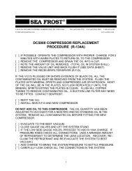
RFD SIGHT GLASS DETAIL<br />
CLEAR OR EMPTY STATIONARY BUBBLES FOAM (LOW CHARGE)<br />
PROPER CHARGE AMOUNT<br />
THE ENGINE DRIVE SYSTEM IS DESIGN<strong>ED</strong> TO HOLD 24 OUNCES. THIS IS EQUAL<br />
TO 2 CANS OF R-<strong>134a</strong> AS SUPPLI<strong>ED</strong> WITH THE SYSTEM. THIS IS THE MAXIMUM<br />
CHARGE. The sight glass must clear by the time the return line (suction/large diameter<br />
line) goes below 32 degrees F.<br />
36
GENERAL INFORMATION<br />
OPERATING PRESSURES will vary with rpm, water temperature, and water flow.<br />
Generally, the discharge will peak with a warm plate in two minutes. Increasing<br />
pressure indicates an overcharge or no water flow. The suction pressure will drop to 25<br />
psi rapidly, and will then drop two pounds per minute or faster to a slight vacuum. The<br />
1/2" suction line will freeze and after extended operation the suction pressure will rest at<br />
a slight vacuum. Suction pressure will drop more rapidly when the seawater is cold. A<br />
vacuum will be indicated sooner. A deep vacuum indicates the V/U is frozen or plugged.<br />
Failure to "pull down" indicates the V/U is malfunctioning or flooding.<br />
The compressor case will feel warm.<br />
The V/U has been operated prior to shipment. There are no field superheat<br />
adjustments.<br />
See pages 43-45 for operating pressure trend charts.<br />
SPECIAL NOTE<br />
WE DO NOT RECOMMEND charging SEA FROST gear with BULK CYLINDERS since<br />
it is hard to determine how much refrigerant has been installed. The feed pressure with<br />
a bulk cylinder can be higher which may cause skipping through the condenser, causing<br />
bubbles in the sight glass. However, if bulk cylinders are used, keep the suction feed<br />
pressure below 20 psi and add vapor only.<br />
R-<strong>134a</strong> will become cloudy and indicate similar foaming in the sight glass as the<br />
pressure on the discharge side of the systems becomes too great. Adding charge to<br />
clear this condition will damage the compressor.<br />
CHECKING THE REFRIGERANT CHARGE ~ PERIODIC INSPECTION<br />
Checking the refrigerant charge must be incorporated into a routine maintenance<br />
schedule.<br />
1. Locate the RFD (receiver filter drier). The location of this part varies from boat to<br />
boat, but it is often found in the engine compartment, in a locker, or beneath the cabin<br />
sole. It is a blue metal can about 9 inches high and 3 inches in diameter, with brass<br />
fittings connecting it to copper tubing. If you do not locate the RFD quickly, follow the<br />
tubing route from the engine compartment to the icebox. Along the route you will find<br />
the RFD along with other SEA FROST components. The RFD has a sight glass for<br />
viewing the flow of the refrigerant.<br />
2. Start the boat's engine. Check to be sure the engine is pumping water.<br />
37
3. Locate the SEA FROST timer panel. With the engine running at a fast idle (900 to<br />
1200 rpm), and while looking into the sight glass in the RFD, have a helper turn the<br />
Panel Timer knob past "10" to cock the switch and start the compressor. The engine<br />
should load. An empty system will put very little load on the engine.<br />
4. MONITOR THE SIGHT GLASS CONTINUALLY. If the sight glass does not show the<br />
presence of refrigerant within a minute of operation the system is empty. TURN OFF<br />
THE COMPRESSOR and follow the procedure in the "TROUBLE SHOOTING" section.<br />
5. If the white foam is evident watch closely for the transition to clear. If the glass<br />
indicates insufficient charge level, additional charge will be needed. Turn off the<br />
compressor. Attach a can of R-<strong>134a</strong> with a properly vented charge hose to the suction<br />
access port. Monitoring the sight glass continually, start compressor and slowly add<br />
refrigerant vapor until the glass clears. Top off with about 4 ounces. Do not<br />
overcharge the system.<br />
6. Feel the SEA FROST plate in the icebox five minutes after starting the compressor.<br />
If the sight glass clears yet the plate temperature does not drop after 5 minutes of<br />
operation, stop the compressor and follow the procedure in "TROUBLE SHOOTING".<br />
7. If the proper charge is indicated, make ice and go sailing.<br />
DISCHARGING THE SYSTEM<br />
Before the connections or components can be disassembled, the refrigerant must be<br />
recovered. Connect a gauge set to the suction access port. Slowly recover the<br />
refrigerant, (keeping the pressure under 20 psi) into an approved reclaiming system.<br />
Do not loosen any connections until the system shows 10” vacuum for 10 minutes.<br />
To discharging an overcharged system, discharge into a recovery machine at the same<br />
20 psi rate for a minute at a time. Be sure the gauge hand wheel is off before starting<br />
the compressor.<br />
38
TROUBLESHOOTING<br />
The most common problems that can occur in a SEA FROST Engine Drive System are:<br />
1. Loss of refrigerant charge resulting from leaks.<br />
2. Moisture or dirt plugging the valve.<br />
3. Compressor malfunction due to loss of refrigerant charge.<br />
4. High-pressure switch cycling due to overcharge or lack of water flow.<br />
STEP 1. Gather information as to the nature of the problem before operating the<br />
system. A leak often leaves a trace of oil. Inspect fittings, hoses, and tubing for wear,<br />
corrosion, and chafe. Do not operate the compressor until the trouble is corrected.<br />
The high pressure switch cycling is indicated by the compressor and indicator lamp<br />
turning off when starting a warm system, or if the cooling water is not flowing.<br />
Determine the condition by checking the water flow from the engine exhaust. If the<br />
water flow is not at fault recover some refrigerant. (See DISCHARGING THE SYSTEM)<br />
The compressor should not be operated during recovery. This is a trial and error<br />
procedure until the compressor stays on without cycling during initial pull down. Check<br />
the sight glass for proper charge. Be sure the sight glass still clears.<br />
For further troubleshooting, attach purged gauges to S/P/U access ports or observe the<br />
temperature of the lines. See pages 43-45 for operating pressure trends.<br />
If the icebox and SEA FROST plate is warm and pressure readings are below 50<br />
psi with the compressor off (in 50 degree F or higher ambient conditions), pressurize the<br />
system with R-<strong>134a</strong> and leak-check.<br />
If the pressure readings are over 50 psi with the compressor off, proceed to check<br />
charge level via sight glass and charge if needed. CHARGE LOSS INDICATES A<br />
LEAK THAT MUST BE CORRECT<strong>ED</strong>.<br />
STEP 2. If the system continues to operate improperly after Step 1, check for moisture<br />
or dirt plugging the valve. Run the system, observing closely the gauge readings and<br />
plate temperature, noting the following.<br />
A. If system is warm upon start-up, a DIRT-PLUGG<strong>ED</strong> Valve will show an immediate<br />
deep vacuum reading on suction side. Consult SEA FROST for cleaning techniques.<br />
B. A MOISTURE-PLUGG<strong>ED</strong> VALVE is indicated by a deep vacuum reading on the<br />
suction side after 1 to 5 minutes of normal operation from warm, FOLLOW<strong>ED</strong> BY any<br />
combination of these symptoms:<br />
The temperature at the compressor discharge fitting and the copper tube at the top<br />
of the condenser drops from hot to warm.<br />
39
The temperature of the suction line from the V/U increases.<br />
Moisture enters either through suction side leaks or during initial installation and will<br />
freeze at the V/U, reducing or eliminating refrigeration activity. Turning off the system<br />
and allowing the V/U to warm to above freezing then restarting, may temporarily solve<br />
the problem. If not, change the RFD as follows.<br />
STEP 3. To change a saturated RFD, allow the system to warm to ambient<br />
temperature, thereby preventing moisture from condensing in the system. A light bulb<br />
in the icebox will speed the warming of the plate. WARNING: BEFORE<br />
DISASSEMBLY OF ANY PART IN THIS SYSTEM BE SURE THE REFRIGERANT IS<br />
COMPLETELY RECOVER<strong>ED</strong>. With a backup wrench holding the brass body of the<br />
Swagelok fittings, loosen and back off the nuts. The tubing may be pulled out of the<br />
fittings. Remove the RFD. Replace only with an identical RFD by size and color. THE<br />
SEA FROST RFD is a drier and also a receiver/filter. The desiccant and the oil in the<br />
<strong>Sea</strong> <strong>Frost</strong> RFD are special to this system and R-<strong>134a</strong>. Installation of the wrong part<br />
or oil will destroy the system.<br />
NOTE: This system contains a measured amount of lubricating oil. Be sure the RFD<br />
being installed is a blue SEA FROST Engine Drive RFD. Record all component<br />
exchanges in the on-board owner's manual.<br />
Follow the "re-make" instructions for Swagelok fittings.<br />
Reminder: To ensure removal of system moisture use a high vacuum pump, and<br />
evacuate the system with the highest possible ambient and plate temperatures. A light<br />
bulb or heat lamp in contact with plate is a good technique.<br />
Recharge. Refer to "New System Charging".<br />
MOISTURE IS A SYMPTOM. Carefully leak-check the low side of the system if<br />
moisture becomes a problem. Moisture leaks in! Look for an oily fitting.<br />
CALL US WITH ANY QUESTIONS<br />
603-868-5720<br />
40
MAINTENANCE FOR UNITS IN TROPICAL WATERS<br />
ZINCS<br />
THIS IS THE MOST IMPORTANT PROC<strong>ED</strong>URE. A FULL FLOW SEA FROST<br />
CONDENSER WITHOUT A ZINC OR WITHOUT THE BONDING STRAP<br />
CONNECT<strong>ED</strong> WILL LAST A VERY SHORT TIME. BE SURE TO CHECK THE WEAR<br />
BY INSPECTION. REPLACE EVERY SIX MONTHS OR SOONER IF INSPECTION<br />
REVEALS EXCESSIVE WEAR.<br />
IF THE ZINC BREAKS IN THE BRASS PLUG, REMOVE THE REMAINING ZINC BY<br />
MELTING IT WITH A PROPANE TORCH.<br />
ALKALI SCALE<br />
CONDENSERS WILL SCALE AFTER SEVERAL YEARS IN WARM WATER CAUSING<br />
HIGHER HEAD PRESSURES DUE TO THE SCALE INTERFERING WITH THE HEAT<br />
EXCHANGE. REMOVE THE ZINC AND PLUG THE HOLE IN THE CONDENSER<br />
WITH A 3/8” NPT PIPE PLUG. WARNING: LEAVING THE ZINC IN PLACE MAKES A<br />
BIG BATTERY UPON ADDING ACID. THIS WILL PRODUCE HEAT AND SMOKE.<br />
DON'T FORGET TO REMOVE THE ZINC. REMOVE THE TOP HOSE ON THE<br />
CONDENSER AND POUR *MURIATIC ACID INTO THE CONDENSER UNTIL IT<br />
BOILS OUT THE TOP.<br />
WARNING: BE SURE TO FOLLOW SAFETY PRECAUTIONS ON THE MURIATIC<br />
ACID CONTAINER.<br />
MOST MURIATIC ACID IS BOTTL<strong>ED</strong> AT 5%-7%. THIS CONCENTRATION IS<br />
WHAT WE RECOMMEND.<br />
BOILING (FOAMING) WILL STOP IN (4 OR 5 MINUTES. THERE IS NO DANGER OF<br />
DAMAGE TO THE CONDENSER. RECONNECT HOSE TO THE ENGINE AND<br />
START THE ENGINE WITH THE THROUGH HULL OPEN. AFTER A MINUTE OR<br />
TWO OF OPERATION TO FLUSH OUT THE ACID, SHUT OFF THE ENGINE AND<br />
THROUGH HULL AND REPLACE THE ZINC.<br />
CLUTCH COILS<br />
THESE FAIL FROM HEAT BREAKING DOWN THE WIRE INSULATION IN THE<br />
WINDING. DAMAGING HEAT CAN BE CAUS<strong>ED</strong> BY OPERATION WITH TOO MUCH<br />
CHARGE AND BY SCALING. CLEAN THE CONDENSER. BE SURE THE CHARGE<br />
IS MINIMUM FOR A CLEAR GLASS. NO MORE THAN 24 ozs IS NE<strong>ED</strong><strong>ED</strong> FOR<br />
MOST SYSTEMS. A SINGLE PLATE OR BLOCK SYSTEM WILL NE<strong>ED</strong> LESS THAN<br />
24 ozs OF REFRIGERANT.<br />
41