Insulated Control Dampers, Model ICD - Greenheck
Insulated Control Dampers, Model ICD - Greenheck
Insulated Control Dampers, Model ICD - Greenheck

Create successful ePaper yourself
Turn your PDF publications into a flip-book with our unique Google optimized e-Paper software.
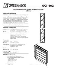
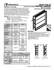
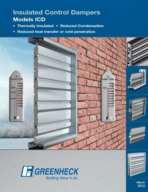
<strong>Insulated</strong> <strong>Control</strong> <strong>Dampers</strong><br />
<strong>Model</strong>s <strong>ICD</strong><br />
• Thermally <strong>Insulated</strong> • Reduced Condensation<br />
• Reduced heat transfer or cold penetration<br />
1<br />
March<br />
2012
<strong>Insulated</strong> <strong>Control</strong> <strong>Dampers</strong><br />
®<br />
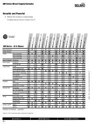
<strong>Greenheck</strong>’s <strong>ICD</strong> series of dampers was developed for applications where it is necessary to minimize<br />
the transfer of heat or cold penetration and reduce condensation. The thermally broken frame provides<br />
an insulating barrier in the ductwork. Thermally broken blades separate the warm and cold air inside the<br />
ductwork. Silicone jamb seals effectively seal the penetration of air from one side of the blade to the other.<br />
Design Features<br />
Variable Symmetric Blade Design (VSB)<br />
<strong>Greenheck</strong>’s Variable Symmetrical Blade (VSB) design<br />
uses a combination of three symmetrical blade sizes (4,<br />
5, and 6 inch) to maximize the free area at any damper<br />
height by reducing blade stop height. Traditional damper<br />
designs use a single blade width that requires oversized<br />
blade stops, limiting free area when the blades are<br />
open. The VSB design allows for consistent operating<br />
characteristics regardless of airflow direction.<br />
• Increases Mounting Flexibility - Symmetrical blades<br />
have identical operating characteristics regardless<br />
of airflow direction. This allows a <strong>Greenheck</strong> control<br />
damper to be mounted in either direction of flow, an<br />
advantage when installing with space constraints.<br />
• Increases Free Area - Traditional damper designs<br />
with a single blade width require oversized blade stops,<br />
limiting free area when the blades are open (Figure 1).<br />
<strong>Greenheck</strong> is able to reduce blade stop height, which<br />
maximizes free area, and increases damper<br />
performance. AMCA certified pressure<br />
drop lets you know that the published data<br />
is accurate to help you better design your<br />
system.<br />
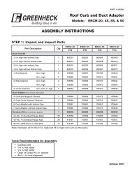
• Reduces Actuator Torque - If an unsymmetrical<br />
blade closes against airflow, a large amount of torque<br />
is needed because the air distribution is unbalanced.<br />
<strong>Greenheck</strong>’s VSB design balances airflow on each side<br />
of a symmetrical blade, reducing the torque required to<br />
operate the damper. The use of symmetrical blades has<br />
allowed <strong>Greenheck</strong> to reduce the sizes and quantities of<br />
actuators used on our dampers.<br />
The <strong>ICD</strong> series damper blades feature thermally broken<br />
airfoil shaped blade with polyurethane foam.<br />
Airflow works<br />
against<br />
actuator<br />
Actuator<br />
Torque<br />
Unbalanced Blade<br />
Requires Higher Torque<br />
Airflow works<br />
against<br />
actuator<br />
Airflow<br />
works with<br />
actuator<br />
Actuator<br />
Torque<br />
Balanced Blade<br />
Requires Less Torque<br />
Parallel versus Opposed Blade Operation<br />
<strong>Greenheck</strong>’s <strong>ICD</strong> series dampers are offered with either<br />
opposed or parallel blade operation. Parallel blade<br />
orientation is typically used when the damper operates<br />
in two positions, open or closed. The damper blades<br />
open or close in the same direction. Opposed blade<br />
orientation is typically used on dampers that modulate<br />
airflow. Adjacent damper blades will open or close<br />
opposite one another.<br />
1/2 in.<br />
(13mm)<br />
1/2 in.<br />
(13mm)<br />
1/2 in.<br />
(13mm)<br />
1/2 in.<br />
(13mm)<br />
2<br />
5 in.<br />
(127mm)<br />
5 in.<br />
(127mm)
<strong>Insulated</strong> <strong>Control</strong> <strong>Dampers</strong><br />
®<br />
Design Features<br />
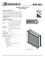
Frame<br />
There are four frame types available:<br />
• Quick Connect for easy connection to duct<br />
• Channel<br />
• Single Flange<br />
• Reversed Flange<br />
The <strong>ICD</strong>-44 features an extruded aluminum frame.<br />
The <strong>ICD</strong>-45 features an aluminum frame with two<br />
polyurethane resin gaps and insulated on four sides<br />
with polystyrene.<br />
Quick<br />
Connect<br />
Channel<br />
Single<br />
Flange<br />
Reverse<br />
Flange<br />
Linkage<br />
<strong>Greenheck</strong>’s <strong>ICD</strong> series dampers have blade linkage<br />
concealed in the insulated frame. This prevents any<br />
transfer point for cold or heat, unlike some of our<br />
competitor’s products. The linkage is engineered to<br />
accurately control each and every blade without need<br />
for adjustment.<br />
No Top or Bottom<br />
<strong>ICD</strong> series dampers are designed for installation in<br />
any position with the blades horizontal. As shown, the<br />
damper can be turned over so the actuator is on the left<br />
or right side.<br />
Blade & Jamb Seals<br />
Silicone blade and jamb seals stay flexible in cold<br />
temperatures.<br />
The <strong>ICD</strong>-44 features silicone blade seal with 304SS<br />
jamb seals with optional silicone jamb seals. The<br />
<strong>ICD</strong>-45 features silicone blade and jamb seals.<br />
Bearings<br />
Dual bearing with acetal inner sleeve and flanged outer<br />
bearing features no metal-to-metal or metal-to-plastic<br />
contact.<br />
3
Quick Selection Chart<br />
®<br />
Maximum Velocity ft/min. (m/s)<br />
<strong>ICD</strong>-44<br />
4000<br />
(20.3)<br />
<strong>ICD</strong>-45<br />
4000<br />
(20.3)<br />
Maximum Pressure in. wg (kPa) 8 (2) 8 (2)<br />
Temperature range °F (°C)<br />
Frame<br />
Frame Gauge<br />
-70 to 200<br />
(-56 to 93)<br />
-70 to 200<br />
(-56 to 93)<br />
<strong>Insulated</strong> Thermally Broken Aluminum - X<br />
Aluminum X -<br />
.125 in.<br />
(3.2mm)<br />
.125 in.<br />
(3.2mm)<br />
Channel X O<br />
Frame Type<br />
Quick Connect O X<br />
Reverse Flange O O<br />
Single Flange O O<br />
Blade Action<br />
Parallel O O<br />
Opposed X X<br />
Blade Type <strong>Insulated</strong> Thermally Broken X X<br />
Blade Material Extruded Aluminum Airfoil X X<br />
Blade Seal Silicone X X<br />
Jamb Seal<br />
304SS X -<br />
Silicone O X<br />
Axle Bearings Dual Bearing with Acetal Inner Sleeve X X<br />
Axle Material<br />
Plated Steel X X<br />
304SS O O<br />
Linkage<br />
Plated Steel X X<br />
304SS O O<br />
Anodize O O<br />
Baked Enamel O O<br />
Epoxy O O<br />
Paint Finishes* Hi Pro Polyester O O<br />
Industrial Epoxy O O<br />
Kynar/Hylar (70%) O O<br />
Permatector O O<br />
Sizing<br />
Inches (mm)<br />
Minimum Size<br />
Channel, Single or<br />
Reverse Flange<br />
Quick Connect<br />
Maximum Single Section Size<br />
Maximum Multi<br />
Section Size<br />
Channel, Single or<br />
Reverse Flange<br />
Quick Connect<br />
* Additional lead time is required. Consult factory.<br />
12 x 7<br />
(305 x 178)<br />
12 x 6<br />
(305 x 152)<br />
48 x 74<br />
(1219 x 1880)<br />
144 x 148<br />
(3658 x 3759)<br />
96 x 148<br />
(2438 x 3759)<br />
12 x 7<br />
(305 x 178)<br />
12 x 6<br />
(305 x 152)<br />
48 x 74<br />
(1219 x 1880)<br />
144 x 120<br />
(3658 x 3048)<br />
96 x 120<br />
(2438 x 3048)<br />
4
Damper Performance<br />
Testing Criteria<br />
®<br />
Thermal Performance<br />
During thermal performance test, per ASTM Standard C1363-97<br />
conducted at Architectural Testing Laboratories (ATI), the <strong>ICD</strong>-45<br />
outperformed competitor’s thermally broken dampers.<br />
(Report #53166.01-201-46)<br />
Dry Ice Test<br />
The thermal breaks in the damper blades and frame reduce the<br />
transfer of heat from the “cool side” to the “warm side”. When<br />
compared to a standard airfoil blade design, <strong>ICD</strong> airfoil blade,<br />
with thermal breaks, prevents ice from forming on the opposite<br />
side of the blade.<br />
Specimen Thermal Resistance (R value)<br />
<strong>Greenheck</strong><br />
<strong>ICD</strong>-45<br />
Brand A<br />
Brand B<br />
Leakage Test<br />
<strong>ICD</strong> series dampers meet the IECC (International Energy Conservation Code) requirements for damper<br />
leakage ratings of at 3 cfm/ft 2 @ 1 in. wg (54.8 cmh/m 2 @ .25 kPa) or less when integral to the building<br />
envelope. Leakage testing was performed at Environ Laboratories at a temperature of -40°F. The <strong>ICD</strong>-45 was<br />
rated at less than 3 cfm/ft 2 @ 1 in. wg (54.8 cmh/m 2 @ .25 kPa) or 8 cfm/ft 2 @ 4 in. wg (146.3 cmh/m 2 @ 1 kPa).<br />
Comparing a 36 in. x 36 in. (914mm x 914mm) damper, <strong>Greenheck</strong>’s <strong>ICD</strong> series has the lowest leakage in the<br />
industry.<br />
<strong>Greenheck</strong><br />
Brand A<br />
Brand B<br />
5
Damper Performance<br />
Testing Criteria<br />
®<br />
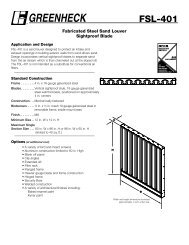
Pressure drop testing was conducted in accordance with AMCA Standard 500-D using the three<br />
configurations shown. All data has been corrected to represent standard air at a density of<br />
.075 lb/ft 3 (1.201 kg/m 3 ).<br />
Actual pressure drop found in any HVAC system is a combination of many factors. This pressure drop<br />
information along with an analysis of other system influences should be used to estimate actual pressure<br />
losses for a damper installed in a given HVAC system.<br />
Figure 5.3 Illustrates a fully ducted damper. This configuration has the lowest pressure drop of the three<br />
test configurations because entrance and exit losses are minimized by straight duct runs upstream and<br />
downstream of the damper.<br />
Figure 5.2 Illustrates a ducted damper exhausting air into an open area. This configuration has a lower<br />
pressure drop than Figure 5.5 because entrance losses are minimized by a straight duct run upstream of the<br />
damper.<br />
Figure 5.5 Illustrates a plenum mounted damper. This configuration has the highest pressure drop because<br />
of extremely high entrance and exit losses due to the sudden changes of area in the system.<br />
5D<br />
6D<br />
Figure 5D 5.3<br />
6D<br />
5D<br />
re 5.3<br />
Figure 5D 5.2<br />
Figure 5.5<br />
re 5.2<br />
D=<br />
4 (W) (H)<br />
3.14<br />
D=Duct length<br />
W=Damper width<br />
H=Damper height<br />
Figure 5.5<br />
4 (W) (H) When comparing a 24 in. x 24 in. (610mm x 610mm)<br />
3.14 damper, <strong>Greenheck</strong>’s <strong>ICD</strong> series has the lowest<br />
pressure drop in the industry which means lower fan<br />
cost or smaller damper size required.<br />
Brand B<br />
Brand A<br />
<strong>Greenheck</strong><br />
6
Damper Performance<br />
Testing Criteria<br />
®<br />
Dimension<br />
Inches (mm)<br />
Velocity -<br />
ft/min. (m/s)<br />
AMCA Figure 5.2 Pressure Drop<br />
12 x 12<br />
(305 x 305)<br />
24 x 24<br />
(610 x 610)<br />
36 x 36<br />
(914 x 914)<br />
Pressure Drop - in. wg (Pa)<br />
12 x 48<br />
(305 x 1219)<br />
48 x 12<br />
(1219 x 305)<br />
500 (2.5) .03 (7.5) .02 (5) .01 (2.5) .01 (2.5) .03 (7.5)<br />
1000 (5.1) .11 (27.4) .08 (19.9) .05 (12.5) .06 (14.9) .14 (34.8)<br />
1500 (7.6) .25 (62.3) .19 (47.3) .11 (27.4) .14 (34.8) .32 (79.7)<br />
2000 (10.2) .45 (112) .34 (84.7) .21 (52.3) .25 (62.3) .57 (142)<br />
2500 (12.7) .71 (176.9) .53 (132) .33 (82.2) .40 (99.6) .89 (221.7)<br />
3000 (15.2) 1.03 (256.6) .77 (191.8) .47 (117.1) .57 (142) 1.29 (321.3)<br />
3500 (17.8) 1.40 (348.7) 1.05 (261.5) .64 (159.4) .78 (194.3) 1.76 (438.4)<br />
4000 (20.3) 1.83 (455.8) 1.37 (341.3) .84 (209.2) 1.02 (254.1) 2.30 (572.9)<br />
Dimension<br />
(in.)<br />
Velocity -<br />
ft/min. (m/s)<br />
AMCA Figure 5.3 Pressure Drop<br />
12 x 12<br />
(305 x 305)<br />
24 x 24<br />
(610 x 610)<br />
36 x 36<br />
(914 x 914)<br />
Pressure Drop - in. wg (Pa)<br />
12 x 48<br />
(305 x 1219)<br />
48 x 12<br />
(1219 x 305)<br />
500 (2.5) .01 (2.5) .01 (2.5) .01 (2.5) .01 (2.5) .04 (10)<br />
1000 (5.1) .04 (10) .03 (7.5) .02 (5) .02 (5) .06 (14.9)<br />
1500 (7.6) .09 (22.4) .08 (19.9) .04 (10) .06 (14.9) .14 (34.8)<br />
2000 (10.2) .17 (42.3) .14 (34.8) .08 (19.9) .10 (24.9) .25 (62.3)<br />
2500 (12.7) .26 (64.7) .22 (54.8) .12 (29.9) .17 (42.3) .40 (99.6)<br />
3000 (15.2) .38 (94.6) .32 (79.7) .18 (44.8) .24 (59.8) .58 (144.5)<br />
3500 (17.8) .52 (129.5) .43 (107.1) .24 (59.8) .33 (82.2) .79 (196.7)<br />
4000 (20.3) .67 (166.9) .57 (142) .32 (79.7) .43 (107.1) 1.03 (256.6)<br />
Dimension<br />
(in.)<br />
Velocity -<br />
ft/min. (m/s)<br />
AMCA Figure 5.5 Pressure Drop<br />
12 x 12<br />
(305 x 305)<br />
24 x 24<br />
(610 x 610)<br />
36 x 36<br />
(914 x 914)<br />
Pressure Drop - in. wg (Pa)<br />
12 x 48<br />
(305 x 1219)<br />
48 x 12<br />
(1219 x 3050<br />
500 (2.5) .05 (12.5) .05 (12.5) .03 (7.5) .04 (10) .05 (12.5)<br />
1000 (5.1) .23 (57.3) .21 (52.3) .14 (34.8) .18 (44.8) .22 (54.8)<br />
1500 (7.6) .52 (129.5) .47 (117.1) .33 (82.2) .42 (104.6) .51 (127)<br />
2000 (10.2) .93 (231.7) .84 (209.2) .58 (144.5) .74 (184.3) .90 (224.2)<br />
2500 (12.7) 1.44 (358.7) 1.32 (328.8) .91 (226.7) 1.16 (288.9) 1.41 (351.2)<br />
3000 (15.2) 2.08 (518.1) 1.9 (473.3) 1.31 (326.3) 1.68 (418.5) 2.04 (508.1)<br />
3500 (17.8) 2.83 (704.9) 2.59 (645.1) 1.79 (445.9) 2.28 (567.9) 2.78 (692.5)<br />
4000 (20.3) 3.70 (921.6) 3.39 (844.4) 2.34 (582.9) 2.98 (742.3) 3.70 (921.6)<br />
<strong>Greenheck</strong> Fan Corporation certifies that the model<br />
<strong>ICD</strong>-44 and <strong>ICD</strong>-45 shown herein is licensed to<br />
bear the AMCA Seal. The ratings shown are based<br />
on tests and procedures performed in accordance<br />
with AMCA Publication 511 and comply with<br />
the requirements of the AMCA Certified Ratings<br />
Programs. The AMCA Certified Ratings Seal applies<br />
to air performance ratings only.<br />
7
The <strong>Greenheck</strong> Difference<br />
<strong>Greenheck</strong> dampers bring the same quality engineering and manufacturing that has earned<br />
<strong>Greenheck</strong> its position as an industry leader. Aggressive research and development keeps<br />
<strong>Greenheck</strong> a major player in the damper and louver industry.<br />
<strong>Greenheck</strong> has the most UL classified dampers and largest<br />
selection of AMCA licensed dampers and louvers in the<br />
industry.<br />
In-House Testing<br />
State-of-the-art laboratory and testing facilities have always<br />
been important to <strong>Greenheck</strong>’s continuing business success.<br />
A laboratory facility devoted exclusively to development and<br />
testing of damper and louver related products for testing to<br />
the latest versions of AMCA, ANSI, ASHRAE, UL, Miami-Dade<br />
County, and other industry standards of performance.<br />
Enjoy <strong>Greenheck</strong>’s extraordinary service, before, during<br />
and after the sale.<br />
<strong>Greenheck</strong> offers added value to our wide selection of top performing, energy-efficient products<br />
by providing several unique <strong>Greenheck</strong> service programs.<br />
• Our Quick Delivery Program ensures shipment of our in-stock products within 24 hours of<br />
placing your order. Our Quick Build made-to-order products can be produced in 1-3-5-10- or<br />
15-day production cycles, depending upon their complexity.<br />
• <strong>Greenheck</strong>’s free Computer Aided Product Selection program (CAPS), rated by many as<br />
the best in the industry, helps you conveniently and efficiently select the right products for the<br />
challenge at hand.<br />
• <strong>Greenheck</strong> has been Green for a long time! Our energy-saving products and ongoing<br />
corporate commitment to sustainability can help you qualify for LEED credits.<br />
• Our 3D service allows you to download at no charge lightweight, easy-to-use AutoDesk <br />
Revit 3D drawings for many of our ventilation products.<br />
Find out more about these special <strong>Greenheck</strong> services at greenheck.com<br />
Our Warranty<br />
<strong>Greenheck</strong> warrants this equipment to be free from defects in material and workmanship for a period<br />
of one year from the shipment date. Any units or parts which prove defective during the warranty<br />
period will be replaced at our option when returned to our factory, transportation prepaid. Motors are<br />
warranted by the motor manufacturer for a period of one year. Should motors furnished by <strong>Greenheck</strong><br />
prove defective during this period, they should be returned to the nearest authorized motor service<br />
station. <strong>Greenheck</strong> will not be responsible for any removal or installation costs.<br />
As a result of our commitment to continuous improvement, <strong>Greenheck</strong> reserves the right to change<br />
specifications without notice.<br />
Prepared to Support<br />
Green Building Efforts<br />
P.O. Box 410 • Schofield, WI 54476-0410 • Phone (715) 359-6171 • greenheck.com<br />
00.DMP.1005 R2 3-2012 IP<br />
Copyright © 2012 <strong>Greenheck</strong> Fan Corp.