13236: WPA Series Waterproof Siren Amplifier - Whelen Engineering
13236: WPA Series Waterproof Siren Amplifier - Whelen Engineering
13236: WPA Series Waterproof Siren Amplifier - Whelen Engineering

You also want an ePaper? Increase the reach of your titles
YUMPU automatically turns print PDFs into web optimized ePapers that Google loves.
Hands-Free <strong>Siren</strong> Activation...<br />
The <strong>WPA</strong> <strong>Series</strong> <strong>Waterproof</strong> <strong>Amplifier</strong>, when installed<br />
according to the wiring diagram above, offers the ability to<br />
activate siren tones using the vehicle’s steering wheel horn ring.<br />
After the horn transfer switch has been set to siren operation,<br />
the hands-free mode is enabled when the customer installed<br />
control switch, connected via the WHT/ORG wire, is closed.<br />
When the hands-free mode is enabled, pressing the horn ring<br />
button will start the Wail siren tone. A second press of the horn<br />
ring button will change the siren tone from Wail to Yelp. A third<br />
press will change the siren tone from Yelp to Piercer. The<br />
siren tones will continue to cycle from Wail to Yelp to Piercer<br />
with each subsequent press of the horn ring button. Two, rapid<br />
presses on the horn ring button ends hands-free siren tone<br />
generation until the horn ring button is pressed again. At that<br />
time the cycle is repeated.<br />
To exit the hands-free mode, end current siren tone, turn off the<br />
customer installed switch for the hands-free mode and return<br />
the horn transfer switch to its normal operating position. Normal<br />
vehicle horn operation is then restored.<br />
To Adjust the Radio Repeat Levels...<br />
Before using the <strong>WPA</strong> <strong>Series</strong> <strong>Waterproof</strong> <strong>Amplifier</strong>, the Radio<br />
Repeat output volume must be adjusted to satisfactory<br />
operating levels. To adjust this level, a small, flat-blade<br />
screwdriver is needed.<br />
Radio Repeat Volume<br />
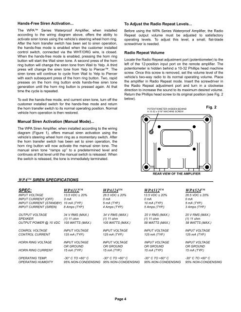
Locate the Radio Repeat adjustment port (potentiometer) to the<br />
left of the 12-position input port on the remote amplifier. The<br />
potentiometer is hidden behind a 10-32 Phillips head machine<br />
screw. Once this screw is removed, set the volume level of the<br />
vehicle’s two-way radio to its normal operating volume. Place<br />
the amplifier in Radio Repeat mode. Insert the screwdriver in<br />
the Radio Repeat adjustment port and turn in a clockwise<br />
direction to increase the sound to its maximum desired volume.<br />
Return the Phillips head screw to its original position (see Fig. 2<br />
below).<br />
POTENTIOMETER (HIDDEN BEHIND<br />
A 10-32 x 5/16" MACHINE SCREW<br />
Fig. 2<br />
Manual <strong>Siren</strong> Activation (Manual Mode)...<br />
The <strong>WPA</strong> <strong>Siren</strong> <strong>Amplifier</strong>, when installed according to the wiring<br />
diagram (Figure 1), offers manual siren activation using the<br />
vehicle’s steering wheel horn ring as a momentary switch. After<br />
the horn transfer switch has been set to siren operation, the<br />
horn ring button will now activate the manual siren tone. The<br />
manual siren tone “ramps up” to a predetermined level and<br />
continues at that level until the manual switch is released. When<br />
the switch is released, the tone is immediately terminated.<br />
<strong>WPA</strong> TM SIREN SPECIFICATIONS<br />
REAR VIEW OF THE AMPLIFIER<br />
SPEC: <strong>WPA</strong>112 TM <strong>WPA</strong>124 TM <strong>WPA</strong>512 TM <strong>WPA</strong>524 TM<br />
INPUT VOLTAGE 13.5 VDC ± 20% 26.5 VDC ± 20% 13.5 VDC ± 20% 26.5 VDC ± 20%<br />
INPUT CURRENT (OFF) 0 mA 0 mA 0 mA 0 mA<br />
INPUT CURRENT (STANDBY) 10 mA (TYP.) 5 mA (TYP.) 10 mA (TYP.) 5 mA (TYP.)<br />
INPUT CURRENT (SIREN) 8 Amps (TYP.) 4 Amps (TYP.) 5 Amps (TYP.) 3 Amps (TYP.)<br />
OUTPUT VOLTAGE 34 V RMS (MAX.) 34 V RMS (MAX.) 25 V RMS (MAX.) 25 V RMS (MAX.)<br />
SPEAKER (1) 11 ohm (1) 11 ohm (1) 11 ohm (1) 11 ohm<br />
OUTPUT POWER @ 15 VDC 105 WATTS (MAX.) 105 WATTS (MAX.) 58 WATTS (MAX.) 58 WATTS (MAX.)<br />
CONROL VOLTAGE INPUT VOLTAGE INPUT VOLTAGE INPUT VOLTAGE INPUT VOLTAGE<br />
CONTROL CURRENT 125 mA (TYP.) 125 mA (TYP.) 125 mA (TYP.) 125 mA (TYP.)<br />
HORN RING VOLTAGE INPUT VOLTAGE INPUT VOLTAGE INPUT VOLTAGE INPUT VOLTAGE<br />
OR GROUND OR GROUND OR GROUND OR GROUND<br />
HORN RING CURRENT 15 mA (TYP.) 15 mA (TYP.) 15 mA (TYP.) 15 mA (TYP.)<br />
OPERATING TEMP. -30° C TO +60° C -30° C TO +60° C -30° C TO +60° C -30° C TO +60° C<br />
OPERATING HUMIDITY 95% NON-CONDENSING 95% NON-CONDENSING 95% NON-CONDENSING 95% NON-CONDENSING<br />
Page 4