

Arduino Pro Mini
Arduino Pro Mini
Arduino Pro Mini

Create successful ePaper yourself
Turn your PDF publications into a flip-book with our unique Google optimized e-Paper software.
www.domko.ru<br />
www.electronshik.ru<br />
<strong>Arduino</strong> <strong>Pro</strong> <strong>Mini</strong><br />
Overview<br />
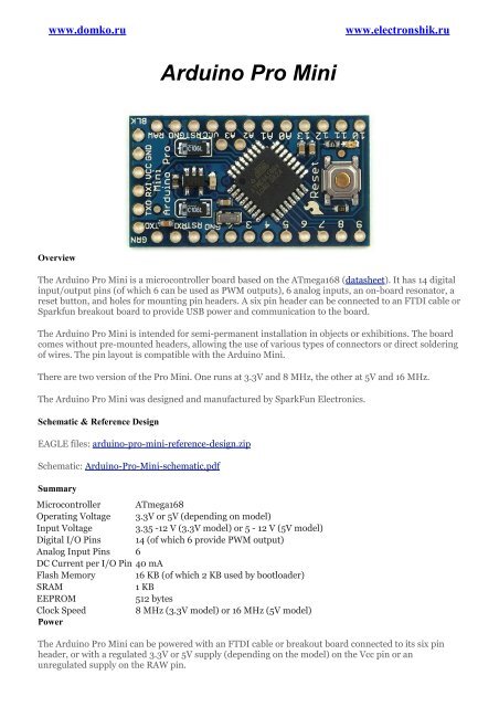
The <strong>Arduino</strong> <strong>Pro</strong> <strong>Mini</strong> is a microcontroller board based on the ATmega168 (datasheet). It has 14 digital<br />
input/output pins (of which 6 can be used as PWM outputs), 6 analog inputs, an on-board resonator, a<br />
reset button, and holes for mounting pin headers. A six pin header can be connected to an FTDI cable or<br />
Sparkfun breakout board to provide USB power and communication to the board.<br />
The <strong>Arduino</strong> <strong>Pro</strong> <strong>Mini</strong> is intended for semi-permanent installation in objects or exhibitions. The board<br />
comes without pre-mounted headers, allowing the use of various types of connectors or direct soldering<br />
of wires. The pin layout is compatible with the <strong>Arduino</strong> <strong>Mini</strong>.<br />
There are two version of the <strong>Pro</strong> <strong>Mini</strong>. One runs at 3.3V and 8 MHz, the other at 5V and 16 MHz.<br />
The <strong>Arduino</strong> <strong>Pro</strong> <strong>Mini</strong> was designed and manufactured by SparkFun Electronics.<br />
Schematic & Reference Design<br />
EAGLE files: arduino-pro-mini-reference-design.zip<br />
Schematic: <strong>Arduino</strong>-<strong>Pro</strong>-<strong>Mini</strong>-schematic.pdf<br />
Summary<br />
Microcontroller ATmega168<br />
Operating Voltage 3.3V or 5V (depending on model)<br />
Input Voltage 3.35 -12 V (3.3V model) or 5 - 12 V (5V model)<br />
Digital I/O Pins 14 (of which 6 provide PWM output)<br />
Analog Input Pins 6<br />
DC Current per I/O Pin 40 mA<br />
Flash Memory 16 KB (of which 2 KB used by bootloader)<br />
SRAM<br />
1 KB<br />
EEPROM<br />
512 bytes<br />
Clock Speed<br />
8 MHz (3.3V model) or 16 MHz (5V model)<br />
Power<br />
The <strong>Arduino</strong> <strong>Pro</strong> <strong>Mini</strong> can be powered with an FTDI cable or breakout board connected to its six pin<br />
header, or with a regulated 3.3V or 5V supply (depending on the model) on the Vcc pin or an<br />
unregulated supply on the RAW pin.
The power pins are as follows:<br />
• RAW. For supplying a raw (unregulated) voltage to the board.<br />
• VCC. The regulated 3.3 or 5 volt supply.<br />
• GND. Ground pins.<br />
Memory<br />
The ATmega168 has 16 KB of flash memory for storing code (of which 2 KB is used for the bootloader).<br />
It has 1 KB of SRAM and 512 bytes of EEPROM (which can be read and written with the EEPROM<br />
library).<br />
Input and Output<br />
Each of the 14 digital pins on the <strong>Pro</strong> <strong>Mini</strong> can be used as an input or output, using pinMode(),<br />
digitalWrite(), and digitalRead() functions. They operate at 3.3 or 5 volts (depending on the model).<br />
Each pin can provide or receive a maximum of 40 mA and has an internal pull-up resistor<br />
(disconnected by default) of 20-50 kOhms. In addition, some pins have specialized functions:<br />
• Serial: 0 (RX) and 1 (TX). Used to receive (RX) and transmit (TX) TTL serial data. These<br />
pins are connected to the TX-0 and RX-1 pins of the six pin header.<br />
• External Interrupts: 2 and 3. These pins can be configured to trigger an interrupt on a low<br />
value, a rising or falling edge, or a change in value. See the attachInterrupt() function for details.<br />
• PWM: 3, 5, 6, 9, 10, and 11. <strong>Pro</strong>vide 8-bit PWM output with the analogWrite() function.<br />
• SPI: 10 (SS), 11 (MOSI), 12 (MISO), 13 (SCK). These pins support SPI communication,<br />
which, although provided by the underlying hardware, is not currently included in the <strong>Arduino</strong><br />
language.<br />
• LED: 13. There is a built-in LED connected to digital pin 13. When the pin is HIGH value, the<br />
LED is on, when the pin is LOW, it's off.<br />
The <strong>Pro</strong> <strong>Mini</strong> has 6 analog inputs, each of which provide 10 bits of resolution (i.e. 1024 different<br />
values). Four of them are on the headers on the edge of the board; two (inputs 4 and 5) on holes in the<br />
interior of the board. The analog inputs measure from ground to VCC. Additionally, some pins have<br />
specialized functionality:<br />
• I 2 C: 4 (SDA) and 5 (SCL). Support I 2 C (TWI) communication using the Wire library.<br />
There is another pin on the board:<br />
• Reset. Bring this line LOW to reset the microcontroller. Typically used to add a reset button to<br />
shields which block the one on the board.<br />
See also the mapping between <strong>Arduino</strong> pins and ATmega168 ports.<br />
Communication<br />
The <strong>Arduino</strong> <strong>Pro</strong> <strong>Mini</strong> has a number of facilities for communicating with a computer, another <strong>Arduino</strong>,<br />
or other microcontrollers. The ATmega168 provides UART TTL serial communication, which is<br />
available on digital pins 0 (RX) and 1 (TX). The <strong>Arduino</strong> software includes a serial monitor which allows<br />
simple textual data to be sent to and from the <strong>Arduino</strong> board via a USB connection.<br />
A SoftwareSerial library allows for serial communication on any of the <strong>Pro</strong> <strong>Mini</strong>'s digital pins.<br />
The ATmega168 also supports I2C (TWI) and SPI communication. The <strong>Arduino</strong> software includes a<br />
Wire library to simplify use of the I2C bus; see the reference for details. To use the SPI communication,<br />
please see the ATmega168 datasheet.<br />
<strong>Pro</strong>gramming<br />
The <strong>Arduino</strong> <strong>Pro</strong> <strong>Mini</strong> can be programmed with the <strong>Arduino</strong> software (download). For details, see the<br />
reference and tutorials.
The ATmega168 on the <strong>Arduino</strong> <strong>Pro</strong> <strong>Mini</strong> comes preburned with a bootloader that allows you to upload<br />
new code to it without the use of an external hardware programmer. It communicates using the original<br />
STK500 protocol (reference, C header files).<br />
You can also bypass the bootloader and program the ATmega168 with an external programmer; see<br />
these instructions for details.<br />
Automatic (Software) Reset<br />
Rather then requiring a physical press of the reset button before an upload, the <strong>Arduino</strong> <strong>Pro</strong> <strong>Mini</strong> is<br />
designed in a way that allows it to be reset by software running on a connected computer. One of the<br />
pins on the six-pin header is connected to the reset line of the ATmega168 via a 100 nanofarad<br />
capacitor. This pin connects to one of the hardware flow control lines of the USB-to-serial convertor<br />
connected to the header: RTS when using an FTDI cable, DTR when using the Sparkfun breakout<br />
board. When this line is asserted (taken low), the reset line drops long enough to reset the chip. The<br />
<strong>Arduino</strong> software uses this capability to allow you to upload code by simply pressing the upload button<br />
in the <strong>Arduino</strong> environment. This means that the bootloader can have a shorter timeout, as the lowering<br />
of the reset line can be well-coordinated with the start of the upload.<br />
This setup has other implications. When the <strong>Pro</strong> <strong>Mini</strong> is connected to either a computer running Mac<br />
OS X or Linux, it resets each time a connection is made to it from software (via USB). For the following<br />
half-second or so, the bootloader is running on the <strong>Pro</strong>. While it is programmed to ignore malformed<br />
data (i.e. anything besides an upload of new code), it will intercept the first few bytes of data sent to the<br />
board after a connection is opened. If a sketch running on the board receives one-time configuration or<br />
other data when it first starts, make sure that the software with which it communicates waits a second<br />
after opening the connection and before sending this data.<br />
Physical Characteristics<br />
The dimensions of the <strong>Pro</strong> <strong>Mini</strong> PCB are approximately 0.7" x 1.3".


