

manual-Doodle bot.cdr
manual-Doodle bot.cdr
manual-Doodle bot.cdr

You also want an ePaper? Increase the reach of your titles
YUMPU automatically turns print PDFs into web optimized ePapers that Google loves.
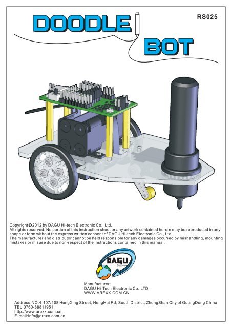
DOODLE BOTRS025Copyright C 2012 by DAGU Hi-tech Electronic Co., Ltd.All rights reserved. No portion of this instruction sheet or any artwork contained herein may be reproduced in anyshape or form without the express written consent of DAGU Hi-tech Electronic Co., Ltd.The manufacturer and distributor cannot be held responsible for any damages occurred by mishandling, mountingmistakes or misuse due to non-respect of the instructions contained in this <strong>manual</strong>.Manufacturer:DAGU Hi-Tech Electronic Co.,LTDWWW.AREXX.COM.CNAddress:NO.4-107/108 HengXing Street, HengHai Rd, South District, ZhongShan City of GuangDong ChinaTEL:0760-88811951http://www.arexx.com.cnE-mail:info@arexx.com.cn
ContentsProduct descriptionWarningsRequired toolsParts listAssembly instructionsWiring instructionsInstalling the softwareChanging the text message and sizeChanging "low battery" sensitivityCreate your own charactorsTroubleshootingTroubleshooting continuedUsing the controller as an Arduino boardSpecificatons333447810101111121212
Product DescriptionThank you for selecting the <strong>Doodle</strong> Bot for your next do-it-your-self project. This kitallows you to build and program a small drawing ro<strong>bot</strong> that can write messages and drawpictures using a large pen, crayon or chalk stick.Product Features1. Arduino compatible ro<strong>bot</strong> controller with USB interface.2. Laser cut, transparent acrylic base plate.3. 2x high torque geared motor with ball bearing.4. 1x high torque miniature servo with ball bearing.5. Rubber tires and pen gripper.Build it now! Realize your dream! Create your next masterpiece!!Warnings:Opened packages can not be returned. Please check package contents before opening.Read the instructions carefully before assembly.Use all tools carefully.Small parts are a choking hazard. Keep this kit away from young children and babiesduring construction and operation.Not for children under 8 years. Not to be used by children except under adultsupervision.Observe the correct polarity of the battery.Keep the battery dry at all times.Do not mix old and new batteries. Do not mix alkaline, standard (carbon-zinc), orrechargeable (nickel-cadmium) batteries.Remove the battery if the kit is not used for a long period of time.Necessary Tools:Please read this <strong>manual</strong> thoroughly before you start assembling the kit. Please follow theassembling instructions exactly to avoid problems. If you work accurately and follow theinstructions in this <strong>manual</strong> exactly, you will quickly assemble your <strong>Doodle</strong> Bot.Before you start you must prepare the following tools:PHILLIPS SCREW DRIVER(included in kit)4x AAA BATTERY(not included)PEN / CRAYON / CHALK(not included)
Parts List:12 3 4 5Base plate 1pc Wheel 2pcs Rubber tire 2pcs Rubber pen gripper 1pc6 7 8 9109g geared motor(two wires) 2pcs12g Miniature servoL shape mounting(three wires) 1pcs Round servo horn 2pcs Servo horn-2 1pc bracket 6pcsL30 distance holder 4pcs11 12 13 14 15M2*5 screw 8pcsM2*5 self-tapping screwwith flange 8pcsM2.3*10 self-tappingscrew with flange 1pc16 17 18 19M2*8 screw 4pcs20M2*5 self-tappingscrew 3pcsM3*6 screw 8pcsController board 1pc battery holder 1pc Collar 1pcRe-useableCable tie 1pc21 22 232425Hall sensor 2pcs8 pole magnet 2pcsAdhesive ring 2pcsSpacer 1pcFiberboard strip 2pcsAssembly Instructions:Step 1: Step 2:3Use the ruler to check thelength of your screws.0mm 10mm 20mm 30mm 40mm 50mm951120 inch 1 inch2 inch95,61x motor111x motor1x servo
Step 3:11Step 4:142521leftmotorStep 5:servorightmotor15Attach the 8 pole magnets to the roundservo horns using the adhesive ringsprovided. Attached to the motors withM2x5mm screws.22237Step 112Loosen the screws holding the fibreboard strips and adjust thewheel sensors so that they are close to the magnets but nottouching. Do not over tighten the screws holding the fibrestrips.Step 6:Step 7:1580mm 10mm 20mm 30mm 40mm 50mmCenter your servo and fit theservo horn so it is pointingstraight down.0 inch 1 inch2 inch19 24 13
Step 8:Step 9:101820Note: The cable tieis re-useable andcan be loosenedwhen the batteriesneed replacing.Step 10:161617Step 11:The large rubber grip can acceptwhiteboard markers, jumbo chalkand large crayons.Try inserting 3 small crayons ofdifferent colours for a rainboweffect.FinishedIf your whiteboard marker is a bittoo small then try wrapping sometape around it to make it thicker inthe middle.4
Wiring Instructions:Once you have assembled the ro<strong>bot</strong> you need to connect the wires. Start by checking that the jumper near thepower switch is selecting 5V for power. If it is set to battery voltage then the sensor outputs might be highenough to damage the digital inputs D2 & D3.Connect the left and right motors as shown in the photo. Make sure the jumpers are on D7, D8, D9 & D10 sothat the processor is connected to the motor driver. Now connect the power wires from the battery. Make sureyou connect the red wire to the +positive connection.Next we need to connect the servo and wheel encoder sensors. These all have three wires - black/brown isthe ground wire and goes to the outer edge of the PCB. The red wire is the +positive and should be in thecenter. The white/orange wire is the signal wire and will be closest to the processor.The right wheel sensor connects to D2, the left wheel sensor connects to D3 and the servo is connected toD12.USBBattery +Battery -PowerSwitchReset+V: Bat/5VD2D3D4D5D6D11D12D13Gnd 5VS5V G T X R XATmega8AD9 D7 D10 D8S5V GndA5A4A3A2A1A0D13LEDLeftmotorRightmotor
Installing the Software:Before you begin you will need to have the Arduino IDE version 0022 installed on your computer. The ArduinoIDE is a free integrated development enviroment that allows you to program Arduino development boards andcompatible products using a simplified version of C++.Do not use later versions as the demonstration software will not work and the compiled program uses morememory. If you do not have this software installed already then download it from here:http://arduino.cc/en/Main/SoftwareYou may also need to install VCP (virtual com port) drivers for the CP2102 USB interface. You can download thelatest drivers from here:http://www.silabs.com/products/mcu/Pages/USBtoUARTBridgeVCPDrivers.aspxThe sample code for this ro<strong>bot</strong> should be available from the distributor. It is also available from the DAGUproduct support site here:https://sites.google.com/site/daguproducts/home/download-pageUnzip the sample code and copy the folder into your sketch pad or other directory of your choice. For Windowsusers this will be a folder called "Arduino" in the "My Documents" folder. Run the Arduino IDE, go to the file menuand select open.Select the "<strong>Doodle</strong>_Bot_Text_Demo" folder and then open the "<strong>Doodle</strong>_Bot_Text_Demo.pde" file.
Make sure the ro<strong>bot</strong> is turned off and connect it to your computer with a USB cable. The control board will bepowered by the USB cable while you upload the program but there will be no power to the motors. Go to the"Tools" menu and select your USB serial port.From the "Tools" menu choose the board type. The <strong>Doodle</strong> Bot controller is compatible with an Arduino NG orolder using an ATmega8 processor.When you upload the program you will see a message indicating the program is compiling, then uploading.When the upload is complete you can disconnect the USB. The ro<strong>bot</strong> is ready to go! Note: It is normal for thero<strong>bot</strong> to wait a few seconds before the program runs.
Changing the text message and size:The first tab contains the setup and loop functions required for all Arduino code. The main loop is where you willprogram the ro<strong>bot</strong> with different messages.When you run the program, the ro<strong>bot</strong> will print the message: "I AM A ROBOT". There are two other samples thatallow the ro<strong>bot</strong> to print the alphabet or the numbers 0-9. Note that if you do not finish your message with"END();" then the ro<strong>bot</strong> will repeat the message continuously.The main loop also checks the battery voltage. If the battery is too flat then the ro<strong>bot</strong> will stop and the D13 LEDwill flash quickly to indicate the battery is flat.To change the size of the text you must change the value of "charsize" in the "Constants.h" tab. This is a wholenumber from 1 to 255 with 1 being the smallest.Changing "low battery" sensitivity:You can change the point at which the ro<strong>bot</strong> decides the battery is too flat in the "constants.h" tab by changingthe value of "lowbat". A value of 512 is approximately 5V. Do not set this too low otherwise the bootloader couldbe corrupted.
Creating your own charactors:If you look in the tabs "Alphabet" and "Numbers" you will see that all the numbers and letters are created usingcombinations of only 4 commands.If you look in the tabs "Alphabet" and "Numbers" you will see that all the numbers and letters are created usingcombinations of only these 4 functions.Go(distance)Turn(angle)Down()Up()Tells the ro<strong>bot</strong> to travel in a straight line. The distance can be a positive or negative wholenumber with negative numbers making the ro<strong>bot</strong> from reverse.Tells the ro<strong>bot</strong> to turn left or right. A positive value turns clockwise, negative turns counterclockwise. Angle can be in 45° steps or values of ±1 to 32 which specifies the number of 22.5°steps.Lowers the pen. The ro<strong>bot</strong> begins drawing.Raises the pen. The ro<strong>bot</strong> stops drawing.Using just these four functions you can write messages and draw pictures. There is a tab called "Charactors"where you can add your own custom charactors and icons. Advanced users may choose to write additionalfunctions to suit their needs.Troubleshooting:Please note: The motors may be a little stiff when new causing the ro<strong>bot</strong> to draw wiggly lines. This problemshould improve after about an hour of use as the motors wear in. The wiggle is a result of one motor being slowerthan the other and the demonstration software attempting to correct this by a very simple method. It is not afault.Problem: When you power the ro<strong>bot</strong> by USB it works ok but when you disconnect the USB and turn the ro<strong>bot</strong> ONthen nothing happens.Solution: Check that the power wires from the battery are connected the correct way around. Make sure yourbatteries have been inserted into the holder correctly. Make sure the batteries are not flat.Problem: When you turn the ro<strong>bot</strong> on it just sits there with the D13 LED flashing quickly.Solution: The ro<strong>bot</strong> has determined that your batteries are flat. Change the batteries.Problem: Instead of drawing straight lines the ro<strong>bot</strong> draws curved lines.Solution: Watch carefully when the demonstration program first runs. If a motor goes backward instead offorward then swap it's wires around.Problem: When the program runs, the ro<strong>bot</strong> turns clockwise when it should turn anticlockwise.Solution: Swap the left and right motors.
Troubleshooting continued:Problem: One of the motors does not turn.Solution: Check that the jumpers are placed correctly on D7, D8, D9 and D10.Problem: When the program runs, the ro<strong>bot</strong> goes forward slightly and then goes in circles.Solution: Make sure your encoders are plugged into the correct sockets as shown (Wiring Instructions).Problem: The pen does not raise or lower. The servo just sits in one position.Solution: Check that the servo is connected to D12. Make sure the signal wire (orange or white) is closest to theprocessor as shown in the wiring instructions. Check that V+ selection jumper is set to +5V.Problem: The USB port is not recognised by your computer or does not show up in the Arduino IDE.Solution: Make sure you do not have anything connected to the serial communications socket while using theUSB cable. Make sure you have the latest CP2102 USB interface drivers installed (Installing the Software).Using the controller as an Arduino board:The DAGU mini driver is software compatible withan Arduino NG. It has been designed specificallyfor ro<strong>bot</strong>ics so it has a few extra features.Up to 8 servos can be connected directly to thePCB by changing the +V selector from 5V to Bat.This allows the servos to be powered directly fromthe battery as the 5V regulator is only capable ofpowering 1 miniature servo under a light load.Analog pins A0-A5 have 5V and Gnd pins availablefor powering 5V sensors. As the SMD chip hasextra pins there are 2 exta analog inputs. A6 is notused although it can be accessed by a solder padunder the PCB. A7 is configured to monitor batteryvoltage. The maximum allowable battery voltage is9V.The dual "H" bridge is capable of driving 2 motors,each with a stall current of 2A or 1 stepper motorwith a maximum of 2A per winding.If you do not wish to use the motor driver then youcan remove the jumpers on D7, D8, D9 and D10.You can then use these pins for alternate purposes.There is a 4 pin female header on the PCB that isintended for use with a wireless transceiver such asan Xbee or Bluetooth module. You can access D0and D1 (Rx and Tx) directly from this header.Battery +Battery -PowerSwitch+V: Bat/5VD2D3D4D5D6D11D12D13Gnd 5VSUSB5V G T X R XATmega8AD9 D7 D10 D8S5VGndResetA5A4A3A2A1A0D13LEDThe ISP socket is the same as a standard Arduinoboard and can be used to re-burn the bootloader.Newer versions of the Arduino IDE will allow you toprogram the board directly from this socket. Notethat there is a small white arrowhead next to pin 1.LeftmotorRightmotorSpecifications:Controller:Processor:Clock speed:FLASH:SRAM:EEPROM:USB interface:Supply voltage:Regulator:Dual "H" bridge:ATmega8A16MHz8K1K512 bytesCP21025V - 9V1A max.2A per motorOutput devices:Servo voltage: 4V - 6VServo torque: 2Kg/cm 6VServo speed: 0.08 sec/60° 6VServo weight: 12gMotor voltage: 6VGearbox torque: 2Kg/cm max.Speed: 125RPM ±10% 6VWeight:9g


