

manual-Doodle bot.cdr
manual-Doodle bot.cdr
manual-Doodle bot.cdr

Create successful ePaper yourself
Turn your PDF publications into a flip-book with our unique Google optimized e-Paper software.
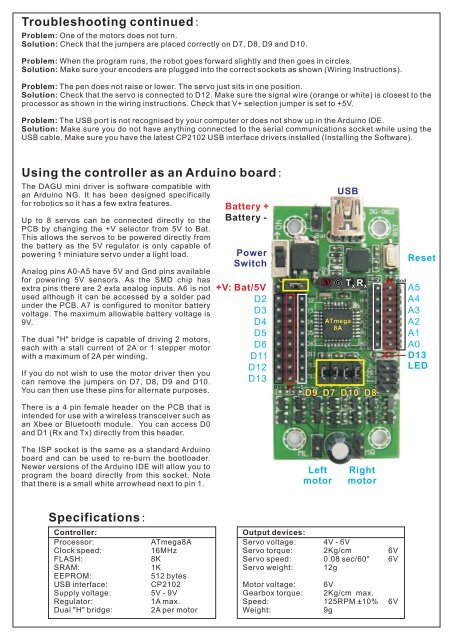
Troubleshooting continued:Problem: One of the motors does not turn.Solution: Check that the jumpers are placed correctly on D7, D8, D9 and D10.Problem: When the program runs, the ro<strong>bot</strong> goes forward slightly and then goes in circles.Solution: Make sure your encoders are plugged into the correct sockets as shown (Wiring Instructions).Problem: The pen does not raise or lower. The servo just sits in one position.Solution: Check that the servo is connected to D12. Make sure the signal wire (orange or white) is closest to theprocessor as shown in the wiring instructions. Check that V+ selection jumper is set to +5V.Problem: The USB port is not recognised by your computer or does not show up in the Arduino IDE.Solution: Make sure you do not have anything connected to the serial communications socket while using theUSB cable. Make sure you have the latest CP2102 USB interface drivers installed (Installing the Software).Using the controller as an Arduino board:The DAGU mini driver is software compatible withan Arduino NG. It has been designed specificallyfor ro<strong>bot</strong>ics so it has a few extra features.Up to 8 servos can be connected directly to thePCB by changing the +V selector from 5V to Bat.This allows the servos to be powered directly fromthe battery as the 5V regulator is only capable ofpowering 1 miniature servo under a light load.Analog pins A0-A5 have 5V and Gnd pins availablefor powering 5V sensors. As the SMD chip hasextra pins there are 2 exta analog inputs. A6 is notused although it can be accessed by a solder padunder the PCB. A7 is configured to monitor batteryvoltage. The maximum allowable battery voltage is9V.The dual "H" bridge is capable of driving 2 motors,each with a stall current of 2A or 1 stepper motorwith a maximum of 2A per winding.If you do not wish to use the motor driver then youcan remove the jumpers on D7, D8, D9 and D10.You can then use these pins for alternate purposes.There is a 4 pin female header on the PCB that isintended for use with a wireless transceiver such asan Xbee or Bluetooth module. You can access D0and D1 (Rx and Tx) directly from this header.Battery +Battery -PowerSwitch+V: Bat/5VD2D3D4D5D6D11D12D13Gnd 5VSUSB5V G T X R XATmega8AD9 D7 D10 D8S5VGndResetA5A4A3A2A1A0D13LEDThe ISP socket is the same as a standard Arduinoboard and can be used to re-burn the bootloader.Newer versions of the Arduino IDE will allow you toprogram the board directly from this socket. Notethat there is a small white arrowhead next to pin 1.LeftmotorRightmotorSpecifications:Controller:Processor:Clock speed:FLASH:SRAM:EEPROM:USB interface:Supply voltage:Regulator:Dual "H" bridge:ATmega8A16MHz8K1K512 bytesCP21025V - 9V1A max.2A per motorOutput devices:Servo voltage: 4V - 6VServo torque: 2Kg/cm 6VServo speed: 0.08 sec/60° 6VServo weight: 12gMotor voltage: 6VGearbox torque: 2Kg/cm max.Speed: 125RPM ±10% 6VWeight:9g


