LG_iV5_Manual_EN.pdf(4.61 MB) - Valiadis
LG_iV5_Manual_EN.pdf(4.61 MB) - Valiadis
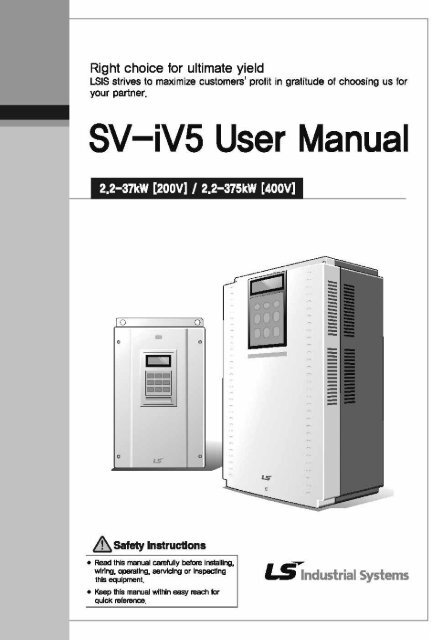
LG_iV5_Manual_EN.pdf(4.61 MB) - Valiadis

You also want an ePaper? Increase the reach of your titles
YUMPU automatically turns print PDFs into web optimized ePapers that Google loves.
Thank you for purchasing LS Vector Drives!<br />
SAFETY INSTRUCTIONS<br />
Safety Instructions<br />
To prevent injury and property damage, follow these instructions.<br />
Incorrect operation due to ignoring instructions will cause harm or damage.<br />
The seriousness of which is indicated by the following symbols.<br />
DANGER<br />
WARNING<br />
This symbol indicates the instant death or<br />
serious injury if you don’t follow instructions<br />
This symbol indicates the possibility of<br />
death or serious injury<br />
CAUTION This symbol indicates the possibility of<br />
injury or damage to property<br />
■ The meaning of each symbol in this manual and on your equipment<br />
is as follows.<br />
This is the safety alert symbol.<br />
Read and follow instructions carefully to avoid dangerous situation.<br />
This symbol alerts the user to the presence of “dangerous voltage”<br />
inside the product that might cause harm or electric shock.<br />
■ After reading this manual, keep it in the place that the user always<br />
can contact easily.<br />
■ This manual should be given to the person who actually uses the<br />
products and is responsible for their maintenance.<br />
WARNING<br />
� Do not remove the cover while power is applied or the unit is<br />
in operation.<br />
Otherwise, electric shock could occur.<br />
i
Safety Instructions<br />
� Do not run the inverter with the front cover removed.<br />
Otherwise, you may get an electric shock due to high voltage terminals<br />
or charged capacitor exposure.<br />
� Do not remove the cover except for periodic inspections or<br />
wiring, even if the input power is not applied.<br />
Otherwise, you may access the charged circuits and get an electric<br />
shock.<br />
� Wiring and periodic inspections should be performed at least<br />
10 minutes after disconnecting the input power and after<br />
checking the DC link voltage is discharged with a meter<br />
(below DC 30V).<br />
Otherwise, you may get an electric shock.<br />
� Operate the switches with dry hands.<br />
Otherwise, you may get an electric shock.<br />
� Do not use the cable when its insulating tube is damaged.<br />
Otherwise, you may get an electric shock.<br />
� Do not subject the cables to scratches, excessive stress,<br />
heavy loads or pinching.<br />
Otherwise, you may get an electric shock.<br />
CAUTION<br />
� Install the inverter on a non-flammable surface. Do not place<br />
flammable material nearby.<br />
Otherwise, fire could occur.<br />
� Disconnect the input power if the inverter gets damaged.<br />
Otherwise, it could result in a secondary accident and fire.<br />
� After the input power is applied or removed, the inverter will<br />
remain hot for a couple of minutes.<br />
Otherwise, you may get bodily injuries such as skin-burn or damage.<br />
� Do not apply power to a damaged inverter or to an inverter<br />
with parts missing even if the installation is complete.<br />
Otherwise, electric shock could occur.<br />
ii
Safety Instructions<br />
� Do not allow lint, paper, wood chips, dust, metallic chips or<br />
other foreign matter into the drive.<br />
Otherwise, fire or accident could occur.<br />
OPERATING PRECAUTIONS<br />
1) Transport and Installation<br />
� Be sure to carry inverter in a proper way suitable for its weight, or it may result<br />
in damage to inverter.<br />
� Do not pile up inverters above allowable limit.<br />
� Be sure to install the inverter as directed in this instruction manual.<br />
� Do not turn off the power supply to the damaged inverter.<br />
� Do not open the front cover while carrying the inverter.<br />
� Do not place the heavy material on the inverter.<br />
� The direction of installation should be observed properly as criterions specified<br />
in this manual show.<br />
� Make sure that you should not put screw, metal material, water, oil and the inflammable<br />
something else.<br />
� Keep in mind that inverter is very vulnerable to drop from the mid air and strong<br />
shock.<br />
� Be certain to use the inverter under the following conditions.<br />
Environment<br />
Ambient temperature - 10 ~ 40 ℃ (Non-frozen)<br />
Humidity<br />
Below 90% RH (Dewdrop should not be<br />
formed)<br />
Storage temperature - 20 ~ 65 ℃<br />
Ambient condition<br />
Free of corrosive gas, inflammable gas, oilwaste<br />
and dust<br />
Altitude/vibration<br />
Below 1000m above sea level, Below<br />
5.9m/sec²(=0.6g)<br />
2) Wiring works<br />
� Do not connect phase-leading capacitors, surge filter, radio noise filter to the<br />
output of inverter.<br />
� Output terminals (terminals named U, V, W respectively) should be connected<br />
in a proper phase sequence.<br />
3) Adjustment before starting trial operation<br />
� Be sure to check relevant parameters for the application before starting trial<br />
operation.<br />
4) Directions<br />
� Be sure not to approach the machine when retry function is selected. The machine<br />
may start working suddenly.<br />
� Stop key on the keypad should be set to be in use. For safety, additional emergency<br />
stop circuit should be required.<br />
� Inverter restarts if alarm condition is cleared while FX/RX signal is on. Therefore,<br />
be sure to operate the alarm reset switch after checking if FX/RX signal is<br />
off.<br />
� Never modify the inverter for inappropriate use.<br />
iii
Safety Instructions<br />
� Motor may not be protected by electronic thermal protection.<br />
� Do not start or stop the inverter by the magnetic contactor installed at the input<br />
of inverter.<br />
� Noise filter should be used for the minimization of troubles by electromagnetic<br />
noise. Electronic equipments close to the inverter should be protected<br />
against the damage caused by troubles.<br />
� Be sure to install the AC reactor at the input of inverter in case of input voltage<br />
unbalance. Otherwise, generator or phase-leading capacitors may be destroyed<br />
by the harmonic current from inverter.<br />
� If 400V class motor is used with the inverter, insulation-enforced motor should<br />
be used or countermeasures against the suppression of micro-surge voltage<br />
generated by the inverter should be carried out. Otherwise, micro-surge voltage<br />
is generated across input terminal for the motor and this voltage lowers allowable<br />
insulation break-down voltage and then, may cause the destruction of<br />
the motor.<br />
� Be sure to set the parameters once more, in case of initialization of parameters,<br />
all values of parameters is set to values of factory setting.<br />
� High speed operation can be set easily, therefore be sure to check the performance<br />
of motor or machine before changing parameter value.<br />
� DC braking function cannot produce a zero-servo torque. If required, additional<br />
equipment should be installed.<br />
� When inverter trip or emergency stop (BX) occurs without keypad connected,<br />
LED on the control board will blink by the interval of 0.5 sec. But LED will blink<br />
by 1 sec when keypad is connected.<br />
5) Countermeasure against malfunction troubles<br />
� If inverter is damaged and then gets into uncontrollable situation, the machine<br />
may lead to the dangerous situation, therefore to avoid this situation, be sure<br />
to install the additional equipments such as brake.<br />
6) Maintenance, inspection and parts replacement<br />
� Do not perform the megger (insulation resistance check) test on the control<br />
board.<br />
� Please refer to Chapter 8 (intervals for parts replacement).<br />
7) Disposal<br />
� Handle the inverter as an industrial waste when disposing of it.<br />
8) General instructions<br />
Many of the diagrams and drawings in this instruction manual show the inverter without<br />
a circuit breaker, a cover or partially open. Never run the inverter like this. Always place<br />
the cover with circuit breakers and follow this instruction manual when operating the<br />
inverter.<br />
iv
Table of Contents<br />
Table of Contents<br />
Chapter1 Introduction<br />
1.1 Key Features -------------------------------------------------------------------------------------------------------------- 1-1<br />
1.2 Inverter Nameplate and Model ---------------------------------------------------------------------------------------- 1-2<br />
Chapter 2 Specification<br />
2.1 Standard Specification ------------------------------------------------------------------------------------------------ 2-1<br />
2.2 Common Specification ------------------------------------------------------------------------------------------------ 2-3<br />
Chapter 3 Installation and Wiring<br />
3.1. Caution on Installation ------------------------------------------------------------------------------------------------- 3-1<br />
3.2 Basic Wiring -------------------------------------------------------------------------------------------------------------- 3-3<br />
3.3 Power Circuit Terminal -------------------------------------------------------------------------------------------------- 3-7<br />
3.4 Control Board and Terminal ----------------------------------------------------------------------------------------- 3-13<br />
3.4.1 Control board jumper description -------------------------------------------------------------------------------- 3-13<br />
3.4.2 Control circuit terminal arrangement ------------------------------------------------------------------------- 3-14<br />
3.4.3 Control circuit terminal function des --------------------------------------------------------------------------- 3-15<br />
3.4.4 Wiring the control circuit terminal ------------------------------------------------------------------------------ 3-18<br />
3.4.5 Caution on wiring pulse encoder --------------------------------------------------------------------------------- 3-18<br />
3.4.6 Encoder wiring and switch setting method (+15V Complementary/Open Collector Type) -------------- 3-19<br />
3.4.7 Encoder wiring and switch setting method (+5V Line Drive) --------------------------------------------- 3-19<br />
3.4.8 Analog input jumper setting (Voltage/Current/Motor NTC/PTC Input) and PNP/NPN input mode<br />
switch setting ----------------------------------------------------------------------------------------------------<br />
3-20<br />
3.5 Terminal of the Auxiliary Power Supply ------------------------------------------------------------------------------ 3-21<br />
Chapter 4 Trial Operation<br />
4.1 Keypad Operation --------------------------------------------------------------------------------------------------- 4-1<br />
4.2 Keypad LCD Display------------------------------------------------------------------------------------------------------ 4-2<br />
4.3 Setting of Parameter Values-------------------------------------------------------------------------------------------- 4-3<br />
4.4 Data Group ------------------------------------------------------------------------------------------------------------- 4-4<br />
4.5 Auto-Tuning --------------------------------------------------------------------------------------------------------- 4-6<br />
4.5.1 Motor & encoder parameter setting for auto-tuning ---------------------------------------------------------- 4-6<br />
4.5.2 Rotational auto-tuning --------------------------------------------------------------------------------------------- 4-7<br />
4.5.3 Standstill auto tuning -------------------------------------------------------------------------------------------- 4-9<br />
4.6 Pulse Encoder Check ---------------------------------------------------------------------------------------------- 4-10<br />
4.7 Operation by Keypad ----------------------------------------------------------------------------------------------- 4-11<br />
4.8 Operation by Control Terminal------------------------------------------------------------------------------------------ 4-12<br />
Chapter 5 Function Code Table<br />
5.1 Display Group (DIS_[][]) ----------------------------------------------------------------------------------------- 5-1<br />
5.2 Digital DIO Group (DIO_[][]) ------------------------------------------------------------------------------------ 5-2<br />
5.3 Parameter Group (PAR_[][]) ------------------------------------------------------------------------------------- 5-4<br />
5.4 Function Group (FUN_[][]) --------------------------------------------------------------------------------------- 5-5<br />
5.5 Control Group (CON_[][]) ---------------------------------------------------------------------------------------- 5-7<br />
5.6 User Group (USR_[][]) -------------------------------------------------------------------------------------------- 5-8<br />
5.7 Second motor Group (2nd_[][]) --------------------------------------------------------------------------------- 5-9<br />
5.8 Analog AIO Group (AIO_[][]) ------------------------------------------------------------------------------------ 5-10<br />
Chapter 6 Function Description<br />
6.1 Display group (DIS_[][]) ------------------------------------------------------------------------------------------ 6-1<br />
6.1.1 DIS_00(Motor control status monitoring) ----------------------------------------------------------------- 6-1<br />
6.1.2 DIS_01 ~ 03 (User display 1, 2, 3)------------------------------------------------------------------------------- 6-1<br />
6.1.3 DIS_04 (Process PID controller ----------------------------------------------------------------------------------- 6-3<br />
6.1.4 DIS_05(Fault display) ---------------------------------------------------------------------------------------- 6-3<br />
6.1.5 DIS_06(User group display selection) ------------------------------------------------------------------------- 6-4<br />
6.2 DIO Group (DIO_[][]) --------------------------------------------------------------------------------------------- 6-5<br />
6.2.1 Jump code (DIO_00) ----------------------------------------------------------------------------------------- 6-5<br />
6.2.2 Multi-function Input terminal ------------------------------------------------------------------------------------- 6-5<br />
v
Table of Contents<br />
1) DIO_01 ~ DIO_07(Multi-function input terminal P1 ~ P7 define) ------------------------------------- 6-5<br />
2) DIO_08(Reversal of Multi-function input terminal) ------------------------------------------------------- 6-17<br />
3) DIO_09 (Low pass filter time constant for the terminals) ----------------------------------------------- 6-17<br />
6.2.3 Multi-function Digital output terminal ----------------------------------------------------------------------- 6-17<br />
1) DIO_10 Inversion of multi-function aux contact output (Relay output, Open collector output) ---- 6-17<br />
2) DIO_41 ~ 43 (Multi-function aux contact output and Open collector output setting) --------------- 6-17<br />
3) DIO_46 (Fault output relay (30A, 30B, 30C)) -------------------------------------------------------------- 6-23<br />
4) DIO_59 ~ 61 (Overload trip enable, level, time)) ----------------------------------------------------- 6-23<br />
5) DIO_97(Operation method when losing command) ------------------------------------------------- 6-23<br />
6.3 Parameter group (PAR_[][]) ------------------------------------------------------------------------------------- 6-24<br />
6.3.1 Jump code (PAR_00) ---------------------------------------------------------------------------------------- 6-24<br />
6.3.2 Parameter group function --------------------------------------------------------------------------------------- 6-24<br />
1) PAR_01(Parameter initialize) ------------------------------------------------------------------------------ 6-24<br />
2) PAR_02 ~ 03(All Parameter Read/Write) --------------------------------------------------------------- 6-24<br />
3) PAR_04(Parameter Lock) ---------------------------------------------------------------------------------- 6-25<br />
4) PAR_05(Password) ----------------------------------------------------------------------------------------- 6-25<br />
6.3.3 Motor parameters setting ----------------------------------------------------------------------------------------- 6-26<br />
1) PAR_07(Motor rating setting) ----------------------------------------------------------------------------- 6-26<br />
2) PAR_08(Motor cap. selection of User) ------------------------------------------------------------------ 6-26<br />
3) PAR_09(Motor cooling method) -------------------------------------------------------------------------- 6-26<br />
4) Encoder parameter (PAR_10 ~ 13) -------------------------------------------------------------------------- 6-26<br />
6.3.4 Encoder S/W error detection (PAR_14 ~ 15) ---------------------------------------------------------------- 6-27<br />
6.3.5 Auto-tuning ---------------------------------------------------------------------------------------------------- 6-29<br />
6.4 Function group (FUN_[][]) --------------------------------------------------------------------------------------- 6-36<br />
6.4.1 Jump code (FUN_00) ---------------------------------------------------------------------------------------- 6-36<br />
6.4.2 Operating method select ---------------------------------------------------------------------------------------- 6-36<br />
1) FUN_01(RUN/STOP source select) ----------------------------------------------------------------------- 6-36<br />
2) FUN_02(Speed setting method) -------------------------------------------------------------------------- 6-37<br />
3) FUN_03(Stop method) ------------------------------------------------------------------------------------- 6-37<br />
6.4.3 Motor Max speed setting (FUN_04) ----------------------------------------------------------------------- 6-37<br />
6.4.4 Multi-step speed and Dwell speed setting methods ---------------------------------------------------------- 6-37<br />
1) FUN_12~19(Multi-step speed 0~7) --------------------------------------------------------------------- 6-37<br />
2) FUN_20(JOG speed command) ------------------------------------------------------------------------------- 6-37<br />
3) FUN_21(Dwell Speed), FUN_22(Dwell time) --------------------------------------------------------------- 6-38<br />
6.4.5 Accel/Decel pattern and time selection ----------------------------------------------------------------------- 6-39<br />
1) FUN_33(Accel/Decel reference speed) --------------------------------------------------------------------- 6-39<br />
2) FUN_40~47(Accel/Decel time 1~4) --------------------------------------------------------------------- 6-39<br />
3) FUN_36 ~ 39(S curve ratio during Accel/Decel 1 ~ 2)------------------------------------------------------ 6-40<br />
4) FUN_48(Deceleration time for zero speed selection) ------------------------------------------------- 6-42<br />
5) FUN_49(Zero speed deceleration time) ----------------------------------------------------------------- 6-42<br />
6) FUN_51(Decel time when BX is ON) -------------------------------------------------------------------- 6-43<br />
7) FUN_52(Pre-excitation) ------------------------------------------------------------------------------------ 6-43<br />
8) FUN_53(Hold Time) ---------------------------------------------------------------------------------------- 6-43<br />
6.4.6 Electronic thermal selection -------------------------------------------------------------------------------------- 6-44<br />
6.4.7 Inverter switching frequency select -------------------------------------------------------------------------- 6-45<br />
1) FUN_57(Inverter switching frequency select) ---------------------------------------------------------- 6-45<br />
2) Setting range and factory setting of switching frequency ----------------------------------------------- 6-46<br />
6.4.8 Power ON Start selection (FUN_58) ------------------------------------------------------------------------- 6-46<br />
6.4.9 Restart after fault reset (FUN_59) ---------------------------------------------------------------------------- 6-47<br />
6.4.10 Restart after fault reset -------------------------------------------------------------------------------------- 6-48<br />
1) FUN_60 (Number of auto restart try)-------------------------------------------------------------------------- 6-48<br />
2) FUN_61(Delay time before auto restart)----------------------------------------------------------------------- 6-48<br />
6.4.11 Wait time for restart upon stop ------------------------------------------------------------------------------- 6-49<br />
6.4.12 Over speed error detection ------------------------------------------------------------------------------------ 6-49<br />
6.4.13 Brake opening and closing setting ---------------------------------------------------------------------------- 6-50<br />
6.4.14 Battery-operated (Battery Run) speed and Input voltage setting ------------------------------- 6-52<br />
6.5 Control group (CON_[][]) ----------------------------------------------------------------------------------------- 6-54<br />
6.5.1 Jump code (CON_00) ---------------------------------------------------------------------------------------- 6-54<br />
6.5.2 Control mode select (CON_01) ----------------------------------------------------------------------------- 6-54<br />
6.5.3 Application mode (CON_02) ------------------------------------------------------------------------------- 6-54<br />
6.5.4 (Automatic speed regulator : ASR ------------------------------------------------------------------------ 6-54<br />
1) CON_05(ASR LPF time constant 1) --------------------------------------------------------------------- 6-54<br />
vi
Table of Contents<br />
2) CON_08(ASR LPF time constant 2) --------------------------------------------------------------------- 6-54<br />
3) CON_03~04(ASR PI Gain 1) ------------------------------------------------------------------------------ 6-55<br />
4) CON_06~07(ASR PI Gain 2) ------------------------------------------------------------------------------ 6-55<br />
5) CON_09(Ramp time for ASR gain transfer) ------------------------------------------------------------- 6-55<br />
6) CON_10 (Motor Speed at the time of ASR Gain transfer)--------------------------------------------------- 6-55<br />
6.5.5 Process PID Control -------------------------------------------------------------------------------------------- 6-57<br />
6.5.6 Draw control --------------------------------------------------------------------------------------------------- 6-59<br />
6.5.7 Droop control -------------------------------------------------------------------------------------------------- 6-61<br />
6.5.8 Torque control ------------------------------------------------------------------------------------------------- 6-63<br />
1) CON_26(Torque reference source selection) ----------------------------------------------------------- 6-63<br />
2) CON_27(Torque reference source) ---------------------------------------------------------------------- 6-63<br />
3) CON_32(Torque Bias source Select) --------------------------------------------------------------------- 6-63<br />
4) CON_33(Torque Bias quantity) --------------------------------------------------------------------------- 6-63<br />
5) CON_35(Torque balance) ---------------------------------------------------------------------------------- 6-64<br />
6) Torque Bias Enable/Disable ------------------------------------------------------------------------------------- 6-64<br />
7) CON_34(Torque Bias F/F) --------------------------------------------------------------------------------- 6-64<br />
8) CON_28 ~ 31 (Torque limit define, Torque limit during FWD RUN /REV RUN/Regenerating) ------ 6-65<br />
9) Torque current reference ------------------------------------------------------------------------------------- 6-66<br />
6.5.9 Speed search (CON_48) ------------------------------------------------------------------------------------- 6-67<br />
6.6 User Group (USR_[][]) -------------------------------------------------------------------------------------------- 6-68<br />
6.6.1 Jump code (USR_00) ---------------------------------------------------------------------------------------- 6-68<br />
6.6.2 Macro ----------------------------------------------------------------------------------------------------------------- 6-68<br />
1) USR_01(Macro init) ---------------------------------------------------------------------------------------- 6-68<br />
2) USR_02(User save) ---------------------------------------------------------------------------------------- 6-68<br />
3) USR_03(User recall) --------------------------------------------------------------------------------------- 6-68<br />
6.6.3 User code define (USR_04 ~ 67) -------------------------------------------------------------------------- 6-68<br />
6.7 2nd Function Group (2nd_[][]) ---------------------------------------------------------------------------------- 6-70<br />
6.7.1 Jump code (2nd_00) ----------------------------------------------------------------------------------------- 6-70<br />
6.7.2 2nd motor control mode selection (2nd_01) ------------------------------------------------------------- 6-70<br />
6.7.3 2nd motor speed setting ------------------------------------------------------------------------------------------- 6-70<br />
1) 2nd_02 : The 2 nd motor maximum speed --------------------------------------------------------------------- 6-70<br />
2) 2nd_04 : The 2 nd digital speed setting ------------------------------------------------------------------------ 6-70<br />
6.7.4 2nd motor parameters related to acceleration and deceleration -------------------------------------------- 6-71<br />
6.7.5 2nd motor parameters related to the pulse encoder ---------------------------------------------------------- 6-71<br />
6.7.6 2nd motor parameters --------------------------------------------------------------------------------------------- 6-71<br />
6.7.7 2nd motor miscellaneous parameters ---------------------------------------------------------------------------- 6-71<br />
6.8 Analog AIO Group (AIO_[][]) ------------------------------------------------------------------------------------ 6-72<br />
6.8.1 Jump code (AIO_[][]) ---------------------------------------------------------------------------------------- 6-72<br />
6.8.2 Multi-function analog input---------------------------------------------------------------------------------------- 6-72<br />
1) AIO_01~60(analog input terminal definition) ---------------------------------------------------------- 6-72<br />
2) Adjusting Bias: Out Y1 and Gain: Out Y2 by Loader ----------------------------------------------------- 6-75<br />
3) Criterion for command loss of Multi analog input Ai1 (AIO_1) -------------------------------------- 6-76<br />
4) Time out for command loss of Multi-function analog input (AIO_73 Time out) --------------------- 6-77<br />
6.8.3 Analog output ----------------------------------------------------------------------------------------------------- 6-77<br />
1) AIO_74 ~ 83 --------------------------------------------------------------------------------------------------- 6-77<br />
2) Adjusting Gain and Bias by keypad -------------------------------------------------------------------------- 6-78<br />
Chapter 7 WEB Control Application<br />
7.1 Change into WEB Control mode ------------------------------------------------------------------------------------ 7-1<br />
7.1.1 Method of changing into Web control mode --------------------------------------------------------------- 7-1<br />
7.2 Loader Display in WEB Control Mode --------------------------------------------------------------------------------- 7-2<br />
7.2.1 Home screen -------------------------------------------------------------------------------------------------- 7-2<br />
7.3 Change of Parameter Group ------------------------------------------------------------------------------------------ 7-2<br />
7.4 Parameter Setting required for Web Control --------------------------------------------------------------------- 7-3<br />
7.4.1 WEB control mode setting (Compulsory) ---------------------------------------------------------------------- 7-3<br />
7.4.2 Line speed command setting (Option) ----------------------------------------------------------------------- 7-3<br />
7.4.3 Diameter hold function setting (Option) -------------------------------------------------------------------- 7-3<br />
7.4.4 Diameter initialization function setting (Compulsory) --------------------------------------------------- 7-4<br />
7.4.5 Tension disable function setting (Compulsory) -------------------------------------------------------------- 7-5<br />
7.4.6 Maximum motor speed setting (Compulsory) --------------------------------------------------------------- 7-5<br />
7.4.7 Minimum defective line speed setting (Compulsory) ---------------------------------------------------- 7-5<br />
7.4.8 Minimum diameter setting (Compulsory) -------------------------------------------------------------------- 7-6<br />
7.4.9 Diameter computation source setting (Compulsory) ---------------------------------------------------- 7-6<br />
vii
Table of Contents<br />
7.4.10 Rewind/Unwind function setting (Compulsory)) ------------------------------------------------------- 7-7<br />
7.4.11 Overwind/Underwind function setting (Compulsory) -------------------------------------------------- 7-7<br />
7.4.12 Tension Reference input setting (Compulsory) ------------------------------------------------------------- 7-9<br />
7.4.13 PID Control feedback source setting (Compulsory) ------------------------------------------------------- 7-11<br />
7.5 Display Group(DIS_[][]) ------------------------------------------------------------------------------------------ 7-11<br />
7.5.1 DIS_01 ~ 03 (User selection display 1, 2, and 3) ------------------------------------------------------- 7-11<br />
7.5.2 Digital input/output group (DIO_[][]) ----------------------------------------------------------------------- 7-12<br />
1) DIO_01 ~ DIO_07 (Definition of multi-function input P1~7) ---------------------------------------- 7-12<br />
2) Multi-function auxiliary output terminal definition (DIO_41 AX1 Define ~ I/O_43 OC1 Define) ------ 7-14<br />
7.5.3 Analog input/output group (AIO_[][]) --------------------------------------------------------------------- 7-14<br />
7.5.4 Function group (FUN_[][]) ---------------------------------------------------------------------------------- 7-15<br />
7.5.5 Control group (CON_[][]) ------------------------------------------------------------------------------------ 7-15<br />
7.6 Function Code of WEB Application Group (WEB_[][])--------------------------------------------------------------- 7-16<br />
7.7 WEB Group Function --------------------------------------------------------------------------------------------------- 7-18<br />
7.7.1 Jump code (WEB_00) ---------------------------------------------------------------------------------------- 7-18<br />
7.7.2 Diameter display ------------------------------------------------------------------------------------------------- 7-18<br />
1) WEB_01 Diameter : Diameter size display ----------------------------------------------------------------- 7-18<br />
2) WEB_02 Current core : Display of initial diameter selected --------------------------------------------- 7-18<br />
7.7.3 Diameter initialization ---------------------------------------------------------------------------------------------- 7-18<br />
1) WEB_03 DiaPreset Src : diameter initialization type setting ---------------------------------------------- 7-18<br />
2) WEB_04(1 st diameter initial value) ----------------------------------------------------------------------- 7-20<br />
3) WEB_05(2 nd diameter initial value) ---------------------------------------------------------------------- 7-20<br />
4) WEB_06(3 rd diameter initial value) ----------------------------------------------------------------------- 7-20<br />
5) WEB_07(4 th diameter initial value) ----------------------------------------------------------------------- 7-20<br />
7.7.4 Speed setting when doing WEB controlling ------------------------------------------------------------------- 7-21<br />
1) WEB_08 MaxMotor SPD : Motor maximum rotating speed in case of minimum diameter ------------ 7-21<br />
2) WEB_09 MinLine SPD : Minimum effective line speed ---------------------------------------------------- 7-21<br />
3) WEB_10 Min Diameter : Minimum diameter --------------------------------------------------------------- 7-22<br />
4) WEB_11 AccDecWeb : Selecting Acceln/Decel Time Setting) --------------------------------------- 7-22<br />
5) WEB_12 Acc TimeWeb : Acceleration time at the time of Web control ---------------------------------- 7-22<br />
6) WEB_13 Dec TimeWeb : Deceleration time at the time of Web control --------------------------------- 7-22<br />
7.7.5 Diameter Computation ------------------------------------------------------------------------------------------- 7-22<br />
1) WEB_14 Diameter Src : Diameter computation type setting --------------------------------------------- 7-22<br />
2) WEB_15 Diameter LPF : Diameter computation LPF time constant --------------------------------------- 7-23<br />
3) WEB_16 False Core : Falsec core value setting ----------------------------------------------------------- 7-23<br />
7.7.6 Winder setting ------------------------------------------------------------------------------------------------- 7-23<br />
1) WEB_17(Rewind/Unwind setting) ------------------------------------------------------------------------ 7-23<br />
2) WEB_18(Overwind/Underwind setting) ----------------------------------------------------------------- 7-24<br />
7.7.7 tension controlling setting --------------------------------------------------------------------------------------- 7-26<br />
1) WEB_19 Tension Input : tension reference input setting ------------------------------------------------- 7-26<br />
2) WEB_20 Taper Type : Taper type setting ------------------------------------------------------------------- 7-26<br />
3) WEB_21 Taper Input : Taper amount input ---------------------------------------------------------------- 7-26<br />
4) WEB_22 Boost Type : Boost type --------------------------------------------------------------------------- 7-27<br />
5) WEB_23 Boost Input : Boost input --------------------------------------------------------------------------- 7-27<br />
6) WEB_24 Stall Type : Stall type ------------------------------------------------------------------------------ 7-28<br />
7) WEB_25 Stall Input : Stall input ------------------------------------------------------------------------------ 7-28<br />
8) WEB_26 Tension Ramp : Setting of ramp in tension reference input ---------------------------------- 7-29<br />
9) WEB_27 Tension Enb : Setting of tension control enable function---------------------------------------- 7-30<br />
7.7.8 WEB PID control ---------------------------------------------------------------------------------------------- 7-30<br />
1) WEB_28 PIDRef Sel : PID reference type setting -------------------------------------------------------- 7-30<br />
2) WEB_29(Dancer Reference position setting) ----------------------------------------------------------- 7-31<br />
3) WEB_30(Process PID Kp1 Gain setting) ----------------------------------------------------------------- 7-31<br />
4) WEB_31(Process PID Kp2 Gain Setting) ---------------------------------------------------------------- 7-31<br />
5) WEB_32(Process PID Ki1 Gain Setting) ----------------------------------------------------------------- 7-31<br />
6) WEB_33(Process PID Ki2 Gain Setting) ----------------------------------------------------------------- 7-31<br />
7) WEB_34(PID Gain Ramp Time Setting) ----------------------------------------------------------------- 7-32<br />
8) WEB_35(Process PID P Gain profiler type setting) ---------------------------------------------------- 7-32<br />
9) WEB_36(Process PID P Gain profiler Gain setting) ---------------------------------------------------- 7-32<br />
10) WEB_37(Process PID D Gain) ---------------------------------------------------------------------------- 7-33<br />
11) WEB_38(Process PID D Gain LPF Time constant) ----------------------------------------------------- 7-33<br />
12) WEB_39(Process PID Positive limit setting) ------------------------------------------------------------ 7-33<br />
13) WEB_40(Process PID Negative limit setting) ----------------------------------------------------------- 7-33<br />
14) WEB_41(Process PID output LPF) ----------------------------------------------------------------------- 7-34<br />
viii
Table of Contents<br />
15) WEB_42(Process PID output Gain for Rewind) -------------------------------------------------------- 7-34<br />
16) WEB_43(Process PID output Gain for Unwind) -------------------------------------------------------- 7-34<br />
17) WEB_44(PID Controller type setting) ------------------------------------------------------------------- 7-34<br />
18) WEB_45(Minimum PID output setting) ----------------------------------------------------------------- 7-34<br />
19) WEB_46 PIDHoldTime : PID controller maintenance time after hold ---------------------------------- 7-36<br />
20) WEB_47(Process PID feedback source setting) ------------------------------------------------------- 7-36<br />
7.7.9 WEB Brake setting -------------------------------------------------------------------------------------------- 7-38<br />
1) WEB_48 WB Enable : WEB break detection function setting -------------------------------------------- 7-38<br />
2) WEB_49 INV WB Delay : Setting of delayed time until WEB break detection ------------------------- 7-38<br />
3) WEB_50 WB Delay : Delayed time in WEB break detection ---------------------------------------------- 7-38<br />
4) WEB_51 WB Level : WEB break detection level ------------------------------------------------------------ 7-38<br />
7.7.10 Up to speed setting ----------------------------------------------------------------------------------------- 7-39<br />
1) WEB_52(Up to speed judgement setting) -------------------------------------------------------------- 7-39<br />
2) WEB_53(Up to speed level setting) ---------------------------------------------------------------------- 7-39<br />
7.7.11 Quick stop time setting ---------------------------------------------------------------------------------------- 7-39<br />
7.7.12 WEB Jog setting --------------------------------------------------------------------------------------------- 7-40<br />
1) WEB_55(Jog speed setting) ------------------------------------------------------------------------------- 7-40<br />
2) WEB_56(Jog Acceleration/Deceleration time setting select) ----------------------------------------- 7-40<br />
3) WEB_57(Jog Acceleration time setting) ----------------------------------------------------------------- 7-40<br />
4) WEB_58(Jog Deceleration time setting) ----------------------------------------------------------------- 7-40<br />
7.7.13 Splicing level setting ------------------------------------------------------------------------------------------- 7-40<br />
Chapter 8 Inspection and Replacement<br />
8.1 Precautions ------------------------------------------------------------------------------------------------------------- 8-1<br />
8.2 Inspection --------------------------------------------------------------------------------------------------------------- 8-1<br />
8.3 Parts Replacement ------------------------------------------------------------------------------------------------- 8-2<br />
Chapter 9 Troubleshooting and Maintenance<br />
9.1 Fault Display -------------------------------------------------------------------------------------------------------- 9-1<br />
9.2 Monitoring Fault Condition ----------------------------------------------------------------------------------------- 9-2<br />
9.3 Fault Reset -------------------------------------------------------------------------------------------------------- 9-3<br />
9.4 Fault Remedy ---------------------------------------------------------------------------------------------------- 9-3<br />
Chapter 10 Option Devices<br />
10.1 Encoder Division Option Board ------------------------------------------------------------------------------------ 10-1<br />
10.1.1 Encoder Division Option Board Installation and WIRING guide ------------------------------------------- 10-1<br />
10.1.2 Wiring guide for Encoder Division Option Board ------------------------------------------------------------ 10-2<br />
10.1.3 Encoder Division Output ---------------------------------------------------------------------------------------- 10-3<br />
Chapter 11 Accessories<br />
11.1 MCCB(LS), ELB(LS), Magnetic contactor(LS), input/output wire specifications --------------------------- 11-1<br />
11.2 AC input fuse, AC reactor, DC reactor ---------------------------------------------------------------------------- 11-2<br />
11.3 The selection of Braking Resistor and the Unit ----------------------------------------------------------------- 11-3<br />
Chapter 12 Dimensions ------------------------------------------------------------------------------------------------------------- 12-1<br />
Chapter 13 Block Diagram ----------------------------------------------------------------------------------------------------------- 13-1<br />
ix
Chapter 1 - Introduction<br />
1.1 Key Features<br />
1. Introduction<br />
This instruction manual is designed for LS STARVERT-<strong>iV5</strong> series Vector Control<br />
Inverters, which have excellent characteristics in speed and torque control with pulse<br />
encoder mounted on the shaft of 3 phase induction motor, and covers installation,<br />
maintenance, wiring and operation for these inverters.<br />
� Current Controlled Vector Control Inverter with Speed Sensor using IGBT as Power Semiconductor Device.<br />
� Tension/Torque Control and Wide Variety of Process Control<br />
� Process PI Control, Draw Control, Droop Control, Synchronous Control, WEB Control etc.<br />
� Auto-tuning of Motor Parameters for Precise Speed/Torque Control: Rotational/Standstill mode<br />
� Encoder error (H/W and S/W) detection function<br />
� Inverter Application<br />
Application Applicable Machine/System Features<br />
� Steel Strip Tension Control<br />
� Paper Mill<br />
Wide Range<br />
Control<br />
of Speed<br />
Process Control � Textile<br />
� Film<br />
� Coater<br />
� Printing Machine<br />
� Lifts (Elevators) High Speed Operation<br />
� Parking<br />
High Starting Torque<br />
Positioning<br />
Hoisting Control<br />
� Stacker Crane<br />
Wide Range<br />
Control<br />
of Speed<br />
� Crane<br />
� Hoist<br />
� Machine Tool High Speed Operation<br />
Machine Control � Wire Drawing High Starting Torque<br />
� Extruder Positioning<br />
Others<br />
�<br />
�<br />
Conveyor<br />
Industrial Washing Machine<br />
High Speed Operation<br />
Positioning<br />
1-1
1.2 Inverter Nameplate and Model<br />
1.2.1 Inverter nameplate (Example)<br />
SV [][][][]<strong>iV5</strong>-2DB<br />
INPUT 200 - 230 V 3 Phase<br />
[][][]A 50/60Hz<br />
OUTPUT 0 - Input V 3 Phase<br />
[][][]A 0 – 3600rpm<br />
[][][]HP / [][][]kW<br />
1.2.2 Inverter Model Name<br />
1. Introduction<br />
SV [][][][] <strong>iV5</strong> – 2 DB (MD) (380V) (<strong>EN</strong>C)<br />
� LS STARVERT Series<br />
� Max. Applicable Motor<br />
022 : 2.2kW ~ 3750 : 375kW<br />
� <strong>iV5</strong> Series<br />
� Input Voltage<br />
2 : 200V Class (200 ~ 230V) ,<br />
4 : 400V Class (380 ~ 480V)<br />
� Built-in DB Circuit<br />
DB : Built-in DB Circuit (DB Resistors Integrated)<br />
Blank : No Built-in DB Circuit (Use external DB Unit)<br />
� MD : Mold Type (2.2~22kW)<br />
DC : DC Power Input<br />
� Input Voltage<br />
(380V) : 380V Input Voltage – 30~220kW(400V)<br />
Blank : Below 22kW (200V/400V) 280~375kW(400V)<br />
� <strong>EN</strong>CODER TYPE<br />
[][][][][][][][][][][]<br />
LS Industrial Systems Co.,Ltd<br />
Input Power Source Specifications<br />
Rated Capacity<br />
Output Power Source Specifications<br />
Running Freq. / Rated Output Current<br />
Output Capacity<br />
Bar Code<br />
Serial Code<br />
① 2.2~220kW ② 280~375kW<br />
- Blank : 5V Line Drive, 15V Open Collector - 5/12/15V <strong>EN</strong>CODER : 5V Line Drive, 15V Open Collector<br />
- 24V <strong>EN</strong>C : 24V Line Drive/Open Collector - 24V <strong>EN</strong>CODER : 24V Line Drive/Open Collector<br />
1-2
Chapter 2 - Specification<br />
2.1 Standard Specification<br />
2. Specification<br />
2.1.1 200V Class (AC power input type)<br />
SV[][][]<strong>iV5</strong>-2(DB) 022 037 055 075 110 150 185 220 300 370<br />
Max. applicable [HP] 3 5 7.5 10 15 20 25 30 40 50<br />
motor output<br />
Note1) [kW] 2.2 3.7 5.5 7.5 11 15 18.5 22 30 37<br />
Capacity [kVA] (Note2)<br />
4.5 6.1 9.1 12.2 17.5 22.5 28.2 33.1 46 55<br />
Rated current [A] 12 16 24 32 46 59 74 88 122 146<br />
Speed 0 ~ 3600(rpm)<br />
Voltage 200 ~ 230V (Note3)<br />
Input Voltage 3φ 200 ~ 230V(-10% ~ +10%)<br />
Frequency 50 ~ 60Hz(±5%)<br />
Inverter weight [kg(lbs)]<br />
6<br />
(13)<br />
6<br />
(13)<br />
14<br />
(30)<br />
14<br />
(30)<br />
27.5<br />
(60)<br />
27.5<br />
(60)<br />
28<br />
(61)<br />
28<br />
(61)<br />
42<br />
(93)<br />
42<br />
(93)<br />
Output<br />
2.1.2 400V Class (AC power input type)<br />
SV[][][]<strong>iV5</strong>-4(DB) 022 037 055 075 110 150 185 220 300 370<br />
Max.<br />
applicable<br />
[HP] 3 5 7.5 10 15 20 25 30 40 50<br />
motor output<br />
Note 1) [kW] 2.2 3.7 5.5 7.5 11 15 18.5 22 30 37<br />
Capacity [kVA] (Note2)<br />
4.5 6.1 9.1 12.2 18.3 22.9 29.7 34.3 46 57<br />
Rated current [A] 6 8 12 16 24 30 39 45 61 75<br />
Speed 0 ~ 3600(rpm)<br />
Voltage 380 ~ 480V (Note3)<br />
Inverter weight [kg(lbs)]<br />
6<br />
(13)<br />
6<br />
(13)<br />
14<br />
(30)<br />
14<br />
(30)<br />
27<br />
(59)<br />
28<br />
(61)<br />
28<br />
(61)<br />
28<br />
(61)<br />
42<br />
(93)<br />
42<br />
(93)<br />
Output<br />
SV[][][][]<strong>iV5</strong>-4(DB) 450 550 750 900 1100 1320 1600 2200 2800 3150 3750<br />
Max.<br />
applicable<br />
[HP] 60 75 100 120 150 175 215 300 373 420 500<br />
motor output<br />
Note 1) [kW] 45 55 75 90 110 132 160 220 280 315 375<br />
Capacity [kVA] (Note2)<br />
70 85 116 140 170 200 250 329 416 468 557<br />
Rated Current [A] 91 110 152 183 223 264 325 432 546 614 731<br />
Speed 0 ~ 3600(rpm)<br />
Voltage 380 ~ 480V (Note3)<br />
Inverter weight [kg(lbs)]<br />
63<br />
(139)<br />
63<br />
(139)<br />
68<br />
(150)<br />
98<br />
(216)<br />
98<br />
(216)<br />
122<br />
(269)<br />
122<br />
(269)<br />
175<br />
(386)<br />
243<br />
(536)<br />
380<br />
(838)<br />
380<br />
(838)<br />
Voltage 3φ 380 ~ 480V(-10% ~ +10%) (Note4)<br />
Input<br />
Frequency 50 ~ 60 Hz (±5%)<br />
Output<br />
※ The electrical specifications of the MD type (2.2~22kW Class) are the same as the above.<br />
SV[][][]<strong>iV5</strong>-2/4DB(MD) 055 075 110 150 185 220<br />
Inverter weight [kg(lbs)] 7.7(16.9) 7.7(16.9) 13.7(30.2) 13.7(30.2) 20.3(44.7) 20.3(44.7)<br />
2-1
2.1.3 400V Class (DC power input type)<br />
2. Specification<br />
SV[][][]<strong>iV5</strong>-4DC 055 075 110 150 185 220 300 370 450 550<br />
Max.<br />
applicable<br />
motor output<br />
Note1)<br />
Output<br />
[HP] 7.5 10 15 20 25 30 40 50 60 75<br />
[kW] 5.5 7.5 11 15 18.5 22 30 37 45 55<br />
Capacity [kVA] (Note2)<br />
9.1 12.2 18.3 22.9 29.7 34.3 46 57 70 85<br />
Rated Current [A] 12 16 24 30 39 45 61 75 91 110<br />
Speed 0 ~ 3600(rpm)<br />
Voltage<br />
(주 3)<br />
380 ~ 480V<br />
Input rated voltage<br />
(주 5)<br />
DC 540 ~ 680V(+10%)<br />
Inverter weight [kg (lbs)]<br />
12<br />
(26)<br />
12<br />
(26)<br />
24<br />
(53)<br />
24.5<br />
(54)<br />
25<br />
(55)<br />
25<br />
(55)<br />
38.5<br />
(84)<br />
38.5<br />
(84)<br />
50<br />
(110)<br />
50<br />
(110)<br />
SV[][][]<strong>iV5</strong>-4DC 750 900 1100 1320 1600 2200 2800 3150 3750<br />
Max.<br />
applicable<br />
motor output<br />
Note1)<br />
Output<br />
[HP] 100 120 150 175 215 300 373 420 500<br />
[kW] 75 90 110 132 160 220 280 315 375<br />
Capacity [kVA] Note2)<br />
116 140 170 200 250 329 416 468 557<br />
Rated Current [A] 152 183 223 264 325 432 546 614 731<br />
Speed 0 ~ 3600(rpm)<br />
Voltage<br />
( note3)<br />
380 ~ 480V<br />
Input rated voltage DC 540 ~ 680V(+10%) note5)<br />
Inverter weight [kg (lbs)]<br />
55<br />
(121)<br />
79<br />
(174)<br />
79<br />
(174)<br />
98.5<br />
(217)<br />
98.5<br />
(217)<br />
154.5<br />
(340)<br />
206<br />
(454)<br />
Note)<br />
1. It represents the output capacity of maximum applicable motor in case <strong>LG</strong>-OTIS 4- pole motor is used.<br />
2. Rated capacity (=√3*V*I) is calculated based on 220V for 200V class, 440V for 400V class.<br />
3. Maximum output voltage cannot be generated above specified input voltage.<br />
4. Derate the rated current by 10% when the input voltage is in the range of 507 ~ 528V.<br />
5. Rated current is derated by 10 % above 680 VDC of input voltage.<br />
343<br />
(756)<br />
343<br />
(756)<br />
2-2
2.2 Common Specification<br />
Control<br />
Braking<br />
Input<br />
Output<br />
Environm<br />
ent<br />
Items Detailed Specification<br />
Inverter type Voltage source inverter using IGBT<br />
Control method<br />
Speed control<br />
accuracy<br />
Speed setting<br />
resolution<br />
Cut-off frequency of ASR 50Hz<br />
Torque control accuracy 3%<br />
Accel/<br />
Decel<br />
Overload Capacity CT: 150%/1Min<br />
2. Specification<br />
� Field oriented vector control inverter with speed sensor<br />
attached<br />
� Analog setting:<br />
± 0.01%(25 ± 10℃) of max. Speed (1,800 rpm)<br />
� Digital setting:<br />
± 0.01%(0 ~ 40℃) of max. Speed (1,800 rpm)<br />
� Analog setting: ± 0.1% of maximum Speed<br />
� Digital setting: 0.1 rpm<br />
Time setting 0.00 ~ 6000.0 sec (Time unit can be set)<br />
Combination 4 Combinations of acceleration/Deceleration Time<br />
Pattern Linear, S-Curve<br />
Braking method Dynamic braking using external resistors<br />
Braking torque 150%<br />
Braking resistor External braking resistor should be provided.<br />
Speed settings<br />
Analog input<br />
Contact input<br />
Analog output<br />
Contact output<br />
Open Collector 1 Channel (OC1/EG)<br />
� Digital setting via keypad<br />
� Multi-step speed setting by input terminal selection<br />
� Analog input settings of –10~10V or 4~20mA<br />
� Remote setting by option card<br />
� 3 channels (AI1, AI2, AI3*, (AI4,AI5: Extended I/O))<br />
� -10�10V, 10�10V, 0�10V, 10�0V,0�20mA, 20�0mA,<br />
(*AI3(AI5:Extended I/O): Motor NTC/PTC selectable)<br />
� Selectable among 15 different user-defined functions<br />
� AI3, AI5(Motor NTC):only available with <strong>LG</strong>-OTIS motors.<br />
� FX, RX, BX, RST, P1 ~ P7<br />
� Selectable among 42 different user-defined input functions<br />
� 2 channels (AO1, AO2)<br />
� -10V � 10V, 10 � -10V, 0 � 10V, 10 � 0V output<br />
� Selectable among 41 different user-defined functions<br />
� 2 channels (1A-1B, 2A-2B)<br />
� Fault alarm relay: 1 channel (30A-30C, 30B-30C)<br />
Overcurrent, Overvoltage, Low voltage, Inverter overheat,<br />
Inverter thermal sensor malfunction, Motor overheat, Motor<br />
thermal sensor malfunction, Overspeed, Instantaneous IGBT<br />
Protection<br />
gate block (BX), Fuse blown open, External Trip, Pulse encoder<br />
malfunction, Electronic thermal function, Inverter overload,<br />
Ground fault current, IGBT short, Communication error<br />
Indoor, Free of Corrosive gas and Direct sunlight<br />
Installation condition<br />
(Pollution Degree 2)<br />
Ambient temperature -10 ~ 40°C (Non-frozen condition)<br />
Humidity Below RH 90% (Dewdrop should not be formed)<br />
2-3
Items Detailed Specification<br />
Cooling method Forced ventilation by cooling fan<br />
2. Specification<br />
IP Type<br />
IP00: 2.2 ~ 22 kW (MD), 30 ~ 375 kW<br />
IP20: 5.5 ~ 22 kW (Press)<br />
Altitude, Vibration Below 1000m above sea level, Below 5.9m/s 2 (=0.6G)<br />
2-4
Chapter 3 – Installation and Wiring<br />
3.1 Caution on Installation<br />
3. Installation and Wiring<br />
This chapter describes general items for the installation and wiring of an<br />
inverter and includes instruction for wiring to power terminal and control one<br />
and caution in case of wiring, and also explains the function of each terminal<br />
for both power and control.<br />
3.1.1 Do not install the inverter in a location where excessive vibration is present.<br />
Be cautious when installing on presses or moving equipment.<br />
3.1.2 Caution on ambient temperature<br />
Ambient temperature greatly affects inverter lifetime, therefore be sure to keep the ambient<br />
temperature of installation location at –10 to 40℃.<br />
5 cm<br />
Measurement point of<br />
Ambient temperature<br />
3.1.3 Install the inverter on the uninflammable material. The inverter operates at hightemperature.<br />
3.1.4 Avoid a humid and hot location.<br />
SV-<strong>iV5</strong><br />
5 cm<br />
5 cm<br />
3.1.5 Install the inverter in a location free of oil mist and dust.<br />
Totally enclosed panel can be used to protect the inverter against that materials.<br />
3-1
3. Installation and Wiring<br />
3.1.6 Secure the installation space enough to protect the inverter against the overheating.<br />
Min. 5 cm<br />
SV-<strong>iV5</strong><br />
Min. 10 cm<br />
Min. 10 cm<br />
Min. 5cm<br />
3.1.7 Special care should be taken in case the inverter is to be installed in the panel.<br />
In case more than 2 inverters are to be installed or ventilation fan is to be installed in the panel, make<br />
sure that inverter and ventilation fan is properly installed. If they are poorly installed, it causes the<br />
increase of an ambient temperature and less effective ventilation. Therefore, be sure to keep the ambient<br />
temperature of inverter below the allowable temperature.<br />
3.1.8 Install the inverter tightly not to get loose using proper sized bolt or screw.<br />
3-2
3.2 Basic Wiring<br />
� AC Power Input Type:<br />
SV022, 037, 055, 075, 110, 150, 185, 220<strong>iV5</strong>-2(DB)<br />
SV022, 037, 055, 075, 110, 150, 185, 220<strong>iV5</strong>-4(DB)<br />
Main Power Circuit<br />
Control Circuit<br />
3. Installation and Wiring<br />
※ 5G: Encoder power source common terminal for SV022/037<strong>iV5</strong><br />
Note 1) It is used when inverter control circuit is energized from auxiliary power source (220 VAC) separated from<br />
main power supply. Use insulated transformer to separate from main power supply. (Transformer capacity:<br />
Above 100VA recommended)<br />
3-3
� AC Power Input Type<br />
SV300, 370<strong>iV5</strong>-2<br />
3. Installation and Wiring<br />
SV300, 370, 450, 550, 750, 900, 1100, 1320, 1600, 2200, 2800, 3150, 3750<strong>iV5</strong>-4<br />
Note: AC Fans for 300~2200<strong>iV5</strong>-4 series should be changed the input power source of transformer 1 st tap<br />
corresponding with that of inverter. (Factory default is 380VAC)<br />
Main Power Circuit<br />
Control Circuit<br />
※ SIO terminal indication for SV2800~3750<strong>iV5</strong>: PE → P<strong>EN</strong>T, GE → G24X<br />
Note 1) It is used when inverter control circuit is energized from auxiliary power source (220 VAC) without main<br />
power supply. Use insulated transformer to separate from main power supply. (Transformer capacity: above<br />
100VA recommended)<br />
3-4
� DC Power Input Type:<br />
SV055, 075, 110, 150, 185, 220, 2800, 3150, 3705<strong>iV5</strong>-4DC<br />
Main Power Circuit<br />
Control Circuit<br />
Note 1)<br />
Aux. power source<br />
for control circuit<br />
(220V) (50/60Hz)<br />
Multi-function input<br />
Potentiometer<br />
10 k ohm , 1/ 2W<br />
Analog input<br />
(10 ~ -10V)<br />
(- 10 ~ 10 V)<br />
(0~10V)<br />
(10 ~ 0V)<br />
(0~20mA)<br />
(20~0mA)<br />
(Motor NTC / PTC)<br />
DC input<br />
(540 ~ 680 VDC)<br />
Insulated<br />
Trasformer<br />
FWD run /stop command<br />
REV run / stop command<br />
Emergency stop<br />
Fault reset<br />
Multi-function input 1<br />
Multi-function input 2<br />
Multi-function input 3<br />
Multi- function input 4<br />
Multi- function input 5<br />
Multi- function input 6<br />
Multi -function input 7<br />
Common<br />
Power supply (+10 V)<br />
Analog input 1<br />
Analog input 2<br />
Analog input 3<br />
Common<br />
FX<br />
P (+)<br />
N (-)<br />
AC1<br />
AC2<br />
RX<br />
BX<br />
P1 (MM0)<br />
P2 (MM1)<br />
P3 (ATO)<br />
P4 (FHM)<br />
P5 ( BAT)<br />
P6 (BRC )<br />
P7 (MCC)<br />
CM<br />
VREF<br />
AI 1<br />
AI 2<br />
AI 3<br />
5G<br />
G<br />
RST<br />
STARVERT - <strong>iV5</strong><br />
24 V<br />
Power supply (5V)<br />
Common (0V)<br />
Encoder A<br />
Phase input<br />
Encoder B<br />
Phase input<br />
Open collector<br />
output<br />
3. Installation and Wiring<br />
Note ) : Main circuit , : Control circuit<br />
※ SIO terminal indication for SV2800~3750<strong>iV5</strong>: PE → P<strong>EN</strong>T, GE → G24X<br />
Note 1) It is used when inverter control circuit is energized from auxiliary power source (220 VAC) without main<br />
30 A<br />
30 C<br />
30 B<br />
1A<br />
1B<br />
2A<br />
2B<br />
U<br />
V<br />
W<br />
G<br />
PE<br />
GE<br />
A+<br />
A-<br />
B+<br />
B-<br />
RA<br />
GE<br />
RB<br />
GE<br />
AO 1<br />
AO 2<br />
5G<br />
OC 1<br />
EG<br />
Shield<br />
Analog output 1<br />
Analog output 2<br />
Common<br />
IM<br />
E<br />
A phase encoder pulse output<br />
Encoder output Common<br />
B phase encoder pulse output<br />
Encoder output Common<br />
Fault relay output<br />
(~AC250V,1A)<br />
(~DC 30V,1A)<br />
Auxiliary relay<br />
output<br />
(~AC250V,1A)<br />
(~DC 30V,1A)<br />
Open collector<br />
output<br />
(24V,50mA)<br />
Encoder<br />
( Line Drive Type)<br />
Analog<br />
output<br />
(-10 ~ 10V)<br />
(10 ~ -10V)<br />
(0 ~ 10V)<br />
(10 ~0V)<br />
power supply. Use insulated transformer to separate from main power supply. (Transformer capacity: above<br />
100VA recommended)<br />
3-5
� DC Power Input Type:<br />
SV300, 370, 450, 550, 750, 900, 1100, 1320, 1600, 2200<strong>iV5</strong>-4DC<br />
Multi-function input<br />
Potentiometer<br />
10 k ohm , 1/ 2W<br />
Analog input<br />
(10 ~ -10 V)<br />
(- 10 ~ 10 V)<br />
(0~10V)<br />
(10 ~ 0V)<br />
(0~20mA)<br />
(20~0mA)<br />
(Motor NTC / PTC)<br />
Multi-function input 1<br />
Multi-function input 2<br />
Multi-function input 3<br />
Multi- function input 4<br />
Multi- function input 5<br />
Multi- function input 6<br />
Multi -function input 7<br />
Common<br />
Power supply (+10 V)<br />
Analog input 1<br />
Analog input 2<br />
Analog input 3<br />
Common<br />
Note ) : Main circuit ,<br />
FX<br />
P (+)<br />
N (-)<br />
P1 (MM0)<br />
P2 (MM1)<br />
P3 (ATO)<br />
P4 (FHM )<br />
P5 (BAT)<br />
P6 (BRC )<br />
P7 (MCC)<br />
CM<br />
VREF<br />
AI 1<br />
AI 2<br />
AI 3<br />
5G<br />
: Control circuit<br />
STARVERT - <strong>iV5</strong><br />
Power supply (5V)<br />
Common (0V)<br />
Encoder A<br />
Phase input<br />
Encoder B<br />
Phase input<br />
Open collector<br />
output<br />
3. Installation and Wiring<br />
Warning) It must be energized AC220V (50/60Hz) to terminal of FAN1 and FAN2 because 30 ~ 220<br />
kW-4DC series have a cooling fan for AC power drive and MC. If not, Trip (30~160kW: “FAN/MC PWR”,<br />
220kW: “FAN PWR”) will be occurred. The inverter is not operated unless trip is released after AC220V<br />
inputs. The recommended order of power input and cutoff is as shown below.<br />
(The order of power On: 220VAC � P(+)/N(-) � Run, The opder of power Off: Stop � P(+)/N(-)<br />
� 220VAC)<br />
Warning<br />
FAN and MC<br />
Power<br />
(220V)<br />
(50/60Hz)<br />
Note 1)<br />
Aux. power source<br />
for control circuit<br />
(220V) (50/60Hz)<br />
DC input<br />
(540 ~ 680 VDC)<br />
Insulated<br />
Trasformer<br />
Insulated<br />
Trasformer<br />
FWD run /stop command<br />
REV run / stop command<br />
Emergency stop<br />
Fault reset<br />
FAN 1<br />
FAN 2<br />
G<br />
AC1<br />
AC2<br />
RX<br />
BX<br />
RST<br />
24 V<br />
30 A<br />
30 C<br />
30 B<br />
1A<br />
1B<br />
2A<br />
2B<br />
U<br />
V<br />
W<br />
G<br />
PE<br />
GE<br />
A+<br />
A-<br />
B+<br />
B-<br />
RA<br />
GE<br />
RB<br />
GE<br />
AO 1<br />
AO 2<br />
5G<br />
OC 1<br />
EG<br />
Shield<br />
Analog output 1<br />
Analog output 2<br />
Common<br />
IM<br />
E<br />
A phase encoder pulse output<br />
Encoder output Common<br />
B phase encoder pulse output<br />
Encoder output Common<br />
Fault relay output<br />
( ~ AC 250V, 1A)<br />
( ~ DC 30 V, 1A)<br />
Auxiliary relay<br />
output<br />
( ~ AC 250V, 1A)<br />
( ~ DC 30 V, 1A)<br />
Open collector<br />
output<br />
(24V,50mA)<br />
Encoder<br />
( Line Drive Type)<br />
Analog<br />
output<br />
(-10 ~ 10V)<br />
(10 ~ -10V)<br />
(0 ~ 10V)<br />
(10 ~0V)<br />
Note 1) It is used when inverter control circuit is energized from auxiliary power source (220 VAC) without main power<br />
supply. Use insulated transformer to separate from main power supply. (Transformer capacity: above 100VA<br />
recommended)<br />
3-6
3.3 Power Circuit Terminal<br />
3.3.1 Power circuit terminal arrangement<br />
(1) AC power sorce input type<br />
CAUTION<br />
3. Installation and Wiring<br />
Be sure that “N” is not Neutral Line but DCN(-) and P is DCP(+)<br />
� SV022, 037, 055, 075, 110, 150, 185, 220<strong>iV5</strong>-2(DB)<br />
SV022, 037, 055, 075, 110, 150, 185, 220<strong>iV5</strong>-4(DB)<br />
R S T U V W G N(-) B2 B1 P(+)<br />
� SV110, 150, 185, 220<strong>iV5</strong>-2(DB)(MD)<br />
SV110, 150, 185, 220<strong>iV5</strong>-4(DB)(MD) *(MD) : Mold Type<br />
R S T U V W N(-) B2 B1 P(+)<br />
� SV300, 370<strong>iV5</strong>-2<br />
SV300, 370, 450, 550, 750<strong>iV5</strong>-4<br />
R S T G U V W P1(+) P2(+) N(-)<br />
� SV900, 1100, 1320, 1600, 2200<strong>iV5</strong>-4<br />
R S T G U V W P1(+) P2(+) N(-)<br />
� SV2800, 3150, 3750<strong>iV5</strong>-4<br />
R(L1) S(L2) T(L3) P1(+) P2(+) N(-) G U V W<br />
G<br />
3-7
(2) DC power input type<br />
� SV055, 075<strong>iV5</strong>-4DC<br />
U V W N(-) P(+) G<br />
� SV110, 150, 185, 220<strong>iV5</strong>-4DC<br />
G U V W P(+) N(-)<br />
� SV300, 370,450,550,750,900,1100,1320,1600,2200<strong>iV5</strong>-4DC<br />
FAN1 FAN2<br />
� SV2800, 3150, 3750<strong>iV5</strong>-4DC<br />
P(+) N(-) U V W G<br />
3.3.2 Power circuit terminal description<br />
(1) AC power input type<br />
Name Function Description<br />
3. Installation and Wiring<br />
G U V W P(+) N(-)<br />
R, S, T 3 Phase input power supply Connected to 3 phase input power supply<br />
U, V, W Inverter Output Connected to 3 phase induction motor<br />
G Grounding Used for inverter frame earth<br />
B1, B2 Braking Resistor Connected to braking resistor<br />
P1(+), P2(+) DC Reator and DB Unit<br />
Used for DC Reactor, DB Unit and<br />
DC link common connection<br />
P(+) DC Link common DC link common connection<br />
N(-) DB Unit Used for DB Unit and DC link common connection<br />
3-8
(2) DC power input type<br />
Name Function Description<br />
P(+), N(-) DC input power source<br />
3. Installation and Wiring<br />
Connected to DC input power source<br />
Connected from DC power suupy (PWM converter) within<br />
max. 30m<br />
U, V, W Inverter Output Connected to 3-phase induction motor<br />
G Grounding Used for inverter frame earth<br />
FAN1,<br />
FAN2<br />
Internal cooling fan and MC<br />
drive power source<br />
Connected to single-phase 220V AC power source<br />
3.3.3 Cautions to be required for wiring to power circuit terminal<br />
① Connect terminals ( R, S and T) to 3 phase input power supply after checking inverter nameplate<br />
attached on the inverter. Never connect terminals (U, V and W) to 3 phase input power supply. It results in<br />
lethal damage to the inverter.<br />
Input<br />
Voltage<br />
② Never connect the phase advancing capacitor to the inverter output. If already installed, remove the<br />
phase advancing capacitor clearly.<br />
SV-<strong>iV5</strong><br />
③ Cable between inverter output and motor should be less than 30m long. If cable gets long, surge voltage<br />
appears across motor terminals depending on the cable parameters. Especially, in 400V class motor case,<br />
insulation withstanding voltage may be decreased. Use an insulation-enforced motor when 400V class motor<br />
is used.<br />
Distance between inverter and motor Up to 50m Up to 100m Over 100m<br />
Permitted Carrier Frequency Below 10kHz Below 5kHz Below 2.5kHz<br />
(In case of below 3.7 kW, use the cable of output within 100 m)<br />
R S T G U V W<br />
Phase<br />
advancing<br />
capacitor<br />
3-9
3. Installation and Wiring<br />
④ Crimp terminal with insulation cap should be used for the input power supply and the motor.<br />
⑤ After finishing wiring, be certain to remove all the wire or cable scraps inside the inverter.<br />
⑥ Use the shield cable or twist-paired wire for control circuit terminal. Do not put them into the same wiring<br />
duct for the power terminal.<br />
⑦ When wiring is changed after operating the inverter, be sure to check LCD window on the keypad or<br />
charge lamp is turned off. Capacitors inside inverter are charged with high voltage and it may result in lethal<br />
injury.<br />
⑧ Below 22kW inverter, B1 and B2 on the power terminal should not be connected to anything else other<br />
than DB resistors.<br />
3.3.4 Main power circuit wire sizes and grounding wire size<br />
① Main Power Circuit Wire Sizes<br />
If wiring for the main power terminal is not performed properly, it may cause severe damage to inverter or<br />
lethal injury to inverter operator. Be sure to use 600V, 75℃ copper wire.<br />
Wire Size (Cabling standards of IEC 60227-3 or UL508C)<br />
200V<br />
400V<br />
Inverter Capacity<br />
mm2 AWG or kcmil<br />
R, S, T U, V, W R, S, T U, V, W<br />
2.2 kW 2.5 2.5 12 12<br />
3.7 kW 4 4 10 10<br />
5.5 kW 6 6 8 8<br />
7.5 kW 10 10 6 6<br />
11 kW 16 16 4 4<br />
15 kW 25 25 3 3<br />
18.5 kW 35 35 2 2<br />
22 kW 35 35 2 2<br />
30 kW 50 50 1/0 1/0<br />
37 kW 70 70 2/0 2/0<br />
2.2/3.7 kW 2.5 2.5 12 12<br />
5.5 kW 4 4 10 10<br />
7.5 kW 4 4 10 10<br />
11 kW 6 6 8 8<br />
15 kW 10 10 6 6<br />
18.5 kW 16 16 6 8<br />
22 kW 16 16 4 4<br />
30 kW 35 35 4 4<br />
37 kW 25 25 3 3<br />
45 kW 50 50 2 2<br />
55 kW 50 50 1 1<br />
75 kW 70 70 2/0 2/0<br />
90 kW 120 120 4/0 4/0<br />
110 kW 150 150 300 300<br />
3-10
Inverter Capacity<br />
3. Installation and Wiring<br />
Wire Size (Cabling standards of IEC 60227-3 or UL508C)<br />
mm2 AWG or kcmil<br />
R, S, T U, V, W R, S, T U, V, W<br />
132 kW 185 185 350 350<br />
160 kW 240 240 500 500<br />
220 kW 400 400 800 800<br />
280 kW 2 X 240 2 X 240 2 X 500 2 X 500<br />
315 kW 2 X 240 2 X 240 2 X 500 2 X 500<br />
375 kW 2 X 300 2 X 300 2 X 600 2 X 600<br />
1) Apply the rated torque to terminal screws. Loose screws can cause of short circuit or malfunction.<br />
Tighting the screws too much can damage the terminals and cause a short circuit or malfunction.<br />
② Grounding Wire Size and Caution to be taken<br />
� Be sure to ground the motor and the inverter to prevent electric shock injury. (200V class:<br />
ground impedance 100Ω, 400V class: ground impedance 10Ω)<br />
� Connect the inverter ground to the ground terminal exclusively used for the inverter. Do not use<br />
the case of inverter of sash screw for ground.<br />
� It is strongly recommended that as thick a grounding wire as possible be used and wire be short.<br />
Motor Capacity<br />
Ground wire size( mm²)<br />
200V Class 400V Class<br />
2.2 ~ 3.7 kW 4 2.5<br />
5.5 ~ 7.5 kW 6 4<br />
11 ~ 15 kW 16 10<br />
18.5 ~ 22 kW 25 16<br />
30 ~ 37 kW 25 16<br />
45 ~ 75 kW - 25<br />
90 ~ 132 kW - 35<br />
160 ~ 220 kW - 95<br />
280 ~ 315 kW - 185<br />
375 kW - 240<br />
3-11
3.3.5 Wiring DC Reactor (Option) (AC power input: 30kW and higher)<br />
P1 P2<br />
G U V W N<br />
3.3.6 Wiring DB Unit (Option) (AC power input: 30kW and higher)<br />
G U V W<br />
P1 P2 N<br />
DB resistor<br />
3. Installation and Wiring<br />
DC Reactor<br />
DB UNIT<br />
N B2<br />
P/B1<br />
3.3.7 Wiring guide when using both of DC reactor (Option) and DB Unit(option)<br />
(30kW and higher) (AC power input: 30kW and higher)<br />
G U V W<br />
DC Reactor<br />
P1 P2 N<br />
G<br />
DB resistor<br />
DB UNIT<br />
G N B2 P/B1<br />
3-12
3.4 Control Board and Terminal<br />
3.4.1 Control board Jumper description<br />
� Control board Jumper description according to S/W version<br />
3. Installation and Wiring<br />
Set jumper of control board as following, if it is not set rightly, it may result in misworking<br />
(S/W version can be verified in display group of Function code list.)<br />
1) Before S/W V2.00 (V1.XX ~ V1.93)<br />
Set JP1 to OLD in Control board<br />
2) After S/W V2.00 (V2.00 ~ )<br />
Set JP1 to NEW in Control board.(Factory default)<br />
Note) The products which released after 2007 are being set up to “NEW”<br />
� <strong>iV5</strong> Control Board (5.5 ~ 375kW Class)<br />
JP1<br />
OLD :<br />
NEW :<br />
3-13
3.4.2 Control circuit terminal arrangement<br />
� SV022 ~ 2200<strong>iV5</strong><br />
� SV2800 ~ 3750<strong>iV5</strong><br />
3. Installation and Wiring<br />
3-14
3.4.3 Control circuit terminal function description<br />
3. Installation and Wiring<br />
Item Name Function Description<br />
FX<br />
RX<br />
Forward Run /Stop<br />
Command<br />
Reverse Run/Stop<br />
Command<br />
� Forward/Reverse RUN Command is ON when closed to CM in NPN<br />
input mode.<br />
� Motor stops when FX/RX is ON or OFF at the same time.<br />
BX Emergency Stop<br />
� ON when closed to CM in NPN input mode, Free-run to Stop and<br />
deceleration to stop. It does not trigger fault alarm signal.<br />
RST Fault Reset Resets when fault condition is cancelled.<br />
P1(MM0)<br />
� 1 function can be selected among 42 different functions shown<br />
P2(MM1)<br />
below.<br />
(Multi-step speed 1 / 2 / 3, Jog, MOP Up / Down / Save<br />
P3(AT0)<br />
/ Clear, Analog Hold, Main Drive, 2nd function, Accel./Decel.<br />
P4(FHM)<br />
P5(BAT)<br />
Multi-function input<br />
contact<br />
Time selection, 3 Wire RUN, External trip (B contact), Power<br />
failure prevention, Reverse rotation prevention, Process PI<br />
Disable, Timer input, Soft start cancel, ASR P/PI Gain switch-over,<br />
P6(BRC)<br />
ASR P/PI switch-over, Flux command value switch-over, Preexcitation,<br />
Speed/Torque control, Torque limit ON/Off, Torque bias<br />
P7(MCC)<br />
ON/Off, Battery operation On/Off, Low voltage trip detection<br />
prevention)<br />
� In NPN input mode, it turns On when each contact is closed to CM<br />
CM COMMON<br />
terminal.<br />
� In PNP input mode, it turns On when each contact is closed to<br />
external 24V input.<br />
Contact Input<br />
Analog Input<br />
Encoder Input<br />
VREF<br />
AI1<br />
AI2<br />
AI3/Them<br />
Power supply for<br />
analog setting<br />
Voltage/ Current<br />
Signal Input<br />
Voltage input<br />
Motor NTC/PTC Input<br />
� Reference voltage by variable resistor ( + 10V ) : 10kΩ<br />
� Voltage input (-10�10V, 10�-10V, 0�10V, 10�0V)<br />
current input (0�20mA, 20�0mA), Motor NTC/PTC are selectable<br />
via Multi-function Analog input.<br />
� Jumper setting in Voltage Input: Jumper set as default)<br />
� AI1, AI2: Jumper set on left side,<br />
AI3: Switch set on left (“V”) side<br />
� Jumper setting in Current Input<br />
� AI1, AI2: Jumper set on right side<br />
� S/W setting in motor NTC (OTIS motor)/PTC input<br />
� AI3: switch set on right (“Them”) side.<br />
� Selectable 15 functions as following:<br />
(Speed, Process PID controller, Process PI controller feedback,<br />
Draw, Torque, Magnetic flux, Torque bias, Torque limit, Motor<br />
NTC/PTC…)<br />
5G COMMON � COMMON terminal for Analog input<br />
PE P/S (Power supply)<br />
+5V Line Drive Power<br />
GE for Pulse Encoder 1) 0V<br />
A+<br />
A-<br />
Encoder A-phase<br />
signal<br />
� A, B signal for Line Drive Type Encoder.<br />
� Set the JP2 switch at “P5” on I/O PCB and set the JP4 switch to<br />
B+<br />
B-<br />
Encoder B-phase<br />
signal<br />
“LD” for the use of Line Drive.<br />
※ Jumper set as default<br />
PE P/S for Open<br />
+15V Open Collector Power<br />
GE Collector Note1) 0V<br />
PA<br />
PB<br />
Encoder A-phase<br />
signal<br />
Encoder B-phase<br />
signal<br />
� A, B signal for Complementary or Open Collector Type Encoder.<br />
� Set the JP2 switch at “P15” on I/O PCB and set the JP4 switch to<br />
“OC” for the use of Open Collector.<br />
3-15
Item Name Function Description<br />
Encoder<br />
Output<br />
Analog Output<br />
Relay output<br />
Switch<br />
Z+(PZ)<br />
Z-<br />
RA<br />
Encoder Z-phase signal<br />
Encoder signal<br />
output : A-phase<br />
GE Output Common<br />
RB<br />
Encoder signal<br />
output : B-phase<br />
GE Output Common<br />
AO1 Analog Output 1<br />
3. Installation and Wiring<br />
Caution) The usages of Z-phase signal are as follows and its<br />
functions will be available soon.<br />
� Use for Z-phase pulse provided encoders.<br />
� Z+ and Z- signals are used for Line Drive type, so set the JP5<br />
switch to “LD”.<br />
� PZ signal is used for Open Collector type, so set the JP5 switch to<br />
“OC”.<br />
Encoder A, B phase signal output – Open Collector Type Note4<br />
� -10V � 10V, 10 � -10V, 0 � 10V, 10 � 0V output<br />
� Selectable among 41 functions<br />
AO2 Analog Output 2<br />
(Analog input value, Pre Ramp Reference, Post ramp reference, ASR<br />
Input Reference, Motor Rotating Speed, Speed Deviation, ASR<br />
Output, Torque bias, Positive Trq Limit, Negative Trq Limit,<br />
Regeneration Trq Limit, Torque Reference, Torque current ref., Torque<br />
current, Flux reference, Flux Current ref. , Flux Current, ACR output<br />
of axis Q, ACR output of axis D, Voltage reference of axis D, Voltage<br />
reference of axis Q, Output current, Output voltage, Output power,<br />
DC LINK voltage, Process PI reference, Process PI Feedback, Process<br />
PI output, Motor temperature, Motor temperature, Inverter<br />
temperature, Inverter i2t)<br />
5G COMMON � COMMON terminal for Analog Output<br />
1A Multi-function relay<br />
output 1<br />
� Selectable among the following 21 functions;<br />
1B<br />
2A<br />
2B<br />
OC1<br />
EG<br />
(A Contact)<br />
Multi-function relay<br />
output 2<br />
(A Contact)<br />
Open Collector Ouput<br />
30A Fault alarm A contact<br />
30B Fault alarm B contact<br />
(Inverter ready, Zero speed detection, Seed detection, Speed<br />
detection (ABS), Speed arrival, Timer out, Low voltage alarm, run,<br />
regenerating, Motor overheat warning, Inverter overhear warning,<br />
Speed agree, Touque detection, Torque limit detection, Overload<br />
warning, Stop, Steady run, Brake output, WEB brake, UP to speed,<br />
False core)<br />
� Outputs when fault occurs.<br />
� Deactivated in BX condition.<br />
30C COMMON � COMMON for A, B<br />
JP1<br />
Encoder Input-pulse<br />
Type<br />
LD (Line Drive) / OC (Open Collector or Complementary)<br />
JP2 Note3) Encoder Power Supply DC +5V / +12V / +15V selectable usages<br />
JP4 Note4) PNP/NPN Input mode PNP/NPN contact input mode selection<br />
Note 1) Wire Encoder power source according to series I/O board as below:<br />
SV022~2200<strong>iV5</strong> Class: PE: “+” , GE: “―”<br />
SV2800~3750<strong>iV5</strong> Class: P<strong>EN</strong>T: “+”, G24X: “―”<br />
Note 2) I/O board of SV2800~3750<strong>iV5</strong> Class is classified into 2 types: 24V and 5/12/15V Encoder power<br />
Encoder power is set by PIN(AI4(24V), AI5(5V), AI6(12V), AI7(15V))<br />
Note 3) NPN/PNP input mode selection are not supported for SV2800~3750 <strong>iV5</strong> series’ I/O board.<br />
3-16
Note 4) Example wiring of Encoder output<br />
� Additional Functions of Extended I/O(EXTN _ I/O) Control board terminal<br />
Item Name Function Description<br />
Analog Input<br />
AI1<br />
AI2<br />
AI3<br />
AI4<br />
AI5/Them<br />
Encoder Output<br />
(SIO return<br />
pulse)<br />
RA<br />
GE<br />
RB<br />
GE<br />
Voltage Input<br />
Current Input<br />
Voltage Input<br />
Motor NTC/PTC Input<br />
GND<br />
Vcc<br />
Peripheral device<br />
(e.g: PLC Highspeed<br />
Counter<br />
A-phase input<br />
A-phase<br />
COM<br />
B-phase input<br />
B-phase<br />
COM<br />
3. Installation and Wiring<br />
� Extended I/O(EXTN_I/O) board is added analog input AI4, AI5.<br />
� How to use terminal Pin:<br />
- Voltage Input : AI1, AI2,AI3, AI4, AI5<br />
- Current Input : AI1, AI2, AI3, AI4<br />
- Motro NTC/PTC input : AI5<br />
Note) Jumper setting and functions are explained at I/O control<br />
terminal description.<br />
5G COMMON COMMON terminal for Analog Input<br />
Warning! Warning<br />
Wiring must be considered<br />
with input circuit . Because<br />
encoder output is open<br />
collector type. The figure is<br />
shown the wiring when<br />
inverter is connected with<br />
High-speed counter of LSIS<br />
PLC.<br />
3-17
3.4.4 Wiring the control circuit terminal<br />
3. Installation and Wiring<br />
① Shield wire or vinyl insulated wire are highly recommended to be used for the control circuit terminal.<br />
② Be sure to use twisted shield wire if wiring distance gets too long.<br />
③ Wire should be at least as thick as 0.2 ~ 0.8 mm 2 (18 ~ 26 AWG).<br />
④ Screwing torque limit should be kept under 5.2 lb-in.<br />
⑤ Maximum interrupting capacity of auxiliary contact 1, 2 and 3 is of AC 250V/1A, DC 30V/1A.<br />
⑥ Maximum interrupting capacity of fault alarm relay A, B contact is of AC 250V/1A, DC 30V/1A.<br />
⑦ Open collector output 1, 2 and 3 and encoder output can be used below maximum of 24V/100mA.<br />
⑧ Wires for the control circuit terminal should be separated from ones for the power circuit terminal, if possible<br />
and in case wires for both control circuit terminal and the power circuit one cross each other, they should be<br />
crossed at right angles (90°).<br />
Min. distance: 10cm<br />
Wires for Control Circuit<br />
3.4.5 Caution on wiring pulse encoder<br />
1) Check-up of the coupling and alignment of motor shaft and encoder shaft<br />
① Be sure to mount the pulse encoder at the location where it rotates with same speed as the motor does.<br />
(e.g. on the opposite shaft of load side of motor, on the opposite shaft of motor at traction machine)<br />
② In case there is speed slip between the motor shaft and encoder shaft, the motor may not start or it causes<br />
mechanical vibration.<br />
③ Poor alignment of motor and encoder shaft results in torque ripple and causes mechanical vibration which has<br />
the same frequency as the motor speed at the constant speed region.<br />
2) Wiring the pulse encoder<br />
Wires for Main Circuit<br />
Min. distance: 10cm<br />
① Be sure to use twist paired shield wire and ground shield wire to screw for earth on the I/O PCB.<br />
② Signal wires should be separated from the power lines, if possible. Electromagnetic noise may affect the pulse<br />
encoder output signals.<br />
3-18
3. Installation and Wiring<br />
3.4.6 Encodder wiring and switch setting method(+15V Complementary / Open Collector Type)<br />
Shield Wire<br />
3.4.7 Encoder wiring and switch setting method (+5V Line Drive) ※ Jumper set as default<br />
CAUTION<br />
Shield Wire<br />
� NEVER change the switch setting for Encoder Type during inverter run. Otherwise, it may<br />
cause inverter trip, adversely affecting the entire system.<br />
+15V Open Colletcor (OC)<br />
Therefore, verify the switch is correctly set before operation.<br />
+5V Line Drive (LD)<br />
3-19
3. Installation and Wiring<br />
3.4.8 Analog input jumper setting (Voltage/Current/Motor NTC/PTC Input) and PNP/NPN<br />
input mode switch setting<br />
※ Jumper set as default : Voltage Input (Left)<br />
AI1, AI2<br />
Voltage input : Left<br />
Current input : Right<br />
AI3 Switch<br />
Voltage input : Left<br />
Motor NTC/PTC input : Right<br />
※ Factory Default Jumper Setting: NPN (down side)<br />
JP4<br />
PNP :<br />
NPN :<br />
In case of using internal DC 24V [NPN] In case of using external DC 24V [PNP]<br />
P1<br />
CM<br />
CM<br />
JP4<br />
R<br />
SW JP4<br />
(Inside of inverter)<br />
DC 24 V<br />
NPN<br />
DC24V<br />
� Guaranteed PNP type input voltage (external DC 24V): On voltage (DC 19~25.2 V)/ Off voltage (DC<br />
7V or less)<br />
P1<br />
CM<br />
CM<br />
R<br />
SW JP4<br />
(Inside of inverter)<br />
DC 24 V<br />
PNP<br />
3-20
CAUTION<br />
3. Installation and Wiring<br />
� NEVER change the jumper setting during inverter run. Otherwise, it may cause<br />
inverter trip, adversely affecting the entire system.<br />
� Motor NTC input for Analog Input 3 (AI3) is ONLY available when OTIS Motor is<br />
connected.<br />
If user use a motor other than OTIS with different NTC(PTC) specification and use<br />
this function, it will lead to motor overheat and damage to the motor.<br />
� Do not change the setting of PNP/NPN input switch during inverter operation. It can<br />
influence to the system since contact input is changed. Set the switch correctly<br />
before inverter operation.<br />
3.5 Terminal of the Auxiliary Power Supply<br />
3.5.1 The position of the terminal<br />
� SV055 ~ 220<strong>iV5</strong>(Press) (for AC/DC products)<br />
Terminal of the<br />
Auxiliary Power<br />
3-21
� SV900 ~ 2200<strong>iV5</strong>(Press) (for AC/DC products)<br />
� SV2800 ~ 3750<strong>iV5</strong>(Press) (for AC/DC products)<br />
3.5.2 Function description of auxiliary terminal block<br />
3. Installation and Wiring<br />
Symbol Terminal Name Terminal Description Input Power<br />
AC1, AC2 Auxiliary power input<br />
Inputs single-phase<br />
AC input source<br />
220V (-10 ~ +10%), 50/60Hz<br />
3.5.3 Wiring and Precaution of auxiliary terminal block<br />
① Connect the auxiliary power supply through insulated transformer separated with main power supply.<br />
② User polyvinyl chloride insulated wire for auxiliary power cable.<br />
③ User the cable above 0.5mm 2 (20 AWG).<br />
Terminal of the Auxiliary<br />
Power Supply<br />
Terminal of the Auxiliary<br />
Power Supply<br />
3-22
Chapter 4 - Trial Operation<br />
4.1 Keypad Operation<br />
4. Trial Operation<br />
LCD Keypad can display up to 32 alphanumeric characters and monitor or set parameter values to operate<br />
the inverter and the motor properly. As follows are keypad view and explanation on each key/LED on the<br />
keypad.<br />
<br />
0.0rpm SPD<br />
Tq 0.0% 0.0A<br />
Items Name Function Description<br />
MODE Mode<br />
Enables to move to the other groups (Initial Screen →DIO →<br />
PAR → FUN…) and go to the first code in the same group.<br />
PROG Program Enables to modify setting values.<br />
<strong>EN</strong>T Enter<br />
Enables to move to the other groups (Initial Screen ← DIO ←<br />
PAR ← FUN…) and save the changed setting values.<br />
▲(Up) Up Moves to the next code or increments setting values.<br />
Key<br />
▼(Down) Down Moves to the next code or decrements setting values.<br />
SHIFT/ESC Shift/ESC<br />
Acts as Shift key in a setting mode and as ESC key in other<br />
mode.<br />
REV Reverse RUN Reverse RUN command is enabled.<br />
Stop key during inverter operation.<br />
STOP/RESET Stop/Reset Resets fault when inverter returns to normal after fault has<br />
occurred.<br />
FWD Forward RUN Forward RUN command is enabled.<br />
(REV) Reverse RUN<br />
Lit when motor is in reverse revolution.<br />
Blinks on acceleration/deceleration, lit in a constant speed<br />
LED (STOP/RESET) Stop/Reset<br />
Lit when the motor stops.<br />
Blinks when fault has occurred.<br />
(FWD) Forward RUN<br />
Lit when motor is in forward revolution.<br />
Blinks on acceleration/deceleration, lit in a constant speed<br />
4-1
4.2 Keypad LCD Display<br />
4.2.1 LCD Start-up display<br />
0.0rpm SPD<br />
Tq 0.0% 0.0A<br />
No. Function Description<br />
1 Motor speed Real motor speed in RPM (Revolution Per Minute)<br />
2<br />
SPD: Speed control mode<br />
TRQ: Torque control mode<br />
Motor control Mode WEB: WEB control mode<br />
BX: Emergency stop<br />
BAT : Battery-operated mode<br />
3 Generating torque Displays % ratio to the rated torque of a motor.<br />
4 Output current Inverter output current in RMS<br />
4.2.2 Group display<br />
1<br />
1<br />
2<br />
3 4<br />
FUN ▶ Speed1<br />
13 0.0rpm<br />
3 4<br />
2<br />
4. Trial Operation<br />
No. Function Description<br />
1 Parameter group<br />
Displays the name of each parameter group. There are DIS, DIO,<br />
PAR, FUN, CON, AIO, USR and 2 nd group.<br />
2 Code name Displays a code name to be set.<br />
3 Code Number Displays a code name to be set.<br />
4 Code data and unit Displays a code data and a code unit to be set.<br />
4-2
4.3 Setting of Parameter Values<br />
4. Trial Operation<br />
In case inverter is to be in use using a keypad, proper parameter values can be set depending on the load<br />
and operation condition. For more detailed information, refer to Chapter 6.<br />
First, move on to the code in a group where is intended to change parameter value. cursor (■) blinks by<br />
pressing [PROG] key. Parameter value can be set using (SHIFT/ESC)], [▲(Up)] and [▼(Down)] keys and<br />
then can be saved by entering [<strong>EN</strong>T] key.<br />
Note) In some cases, data will not be changed for the following two reasons.<br />
* Some data cannot be changed during inverter operation.<br />
* Parameter data lock function is set. (PAR_04 [Parameter Lock] is enabled)<br />
Example) In case the 1st acceleration time is to be changed from 10(sec) to 15(sec), it can be set as<br />
shown below.<br />
0.0rpm SPD<br />
Tq 0.0% 0.0A<br />
FUN▶ Jump code<br />
00 1<br />
FUN▶ Jump code<br />
00 40<br />
FUN▶ Acc Time-1<br />
40 10.00 sec<br />
FUN▶ Acc Time-1<br />
40 ■10.00 sec<br />
FUN▶ Acc Time-1<br />
40 10.00 sec<br />
FUN▶ Acc Time-1<br />
40 15.00 sec<br />
FUN▶ Acc Time-1<br />
40 15.00 sec<br />
Initial Display<br />
Move to FUN Group by using [MODE] Key<br />
Press [PROG] Key � Enter 40 by [(SHIFT/ESC)], [▲(Up)], [▼(Down)] Key<br />
�[<strong>EN</strong>T]<br />
Acc time 1 is settable.<br />
Press [PROG] Key.<br />
Setting Mode(Cursor(■) appears and blinks)<br />
Move the Cursor(■) to the position to be changed using<br />
[(SHIFT/ESC)] key.<br />
Set the data using [▲(Up)], [▼(Down)]<br />
Save the changed data by pressing [<strong>EN</strong>T] key. (Cursor disappears.)<br />
4-3
4.4 Data Groups<br />
4. Trial Operation<br />
SV-<strong>iV5</strong> series inverters use LCD keypad for user’s convenience. Data groups are divided into 12 groups for<br />
easy access depending on the inverter application.<br />
Name<br />
LCD keypad<br />
(on the upper<br />
left)<br />
Description<br />
Motor speed, Motor control mode, Generating torque, Output<br />
Display group DIS current, User selection display, Process PID output/reference/feedback<br />
value, Fault display, User group display setting and so on.<br />
Digital I/O group DIO Digital input parameters, Digital output parameters and so on.<br />
Parameter group PAR<br />
Parameter initialization, Parameter read / write / lock /password,<br />
Motor related constants, Auto-tuning and so on.<br />
Operating frequency, Operation mode, Stop mode, Acceleration<br />
Function group FUN /deceleration time and pattern, Carrier frequency, Electronic thermal<br />
selection and so on.<br />
Control mode, ASR PI gain, Process PID gain, Draw control setting,<br />
Control group CON Droop control related constants, Torque control related constants,<br />
V/F control related constants and so on.<br />
Exterior group EXT 1) It is displayed when Communication option board is installed.<br />
Communication setting parameter and so on.<br />
Analog I/O group AIO Analog Input or Output Parameter and so on.<br />
User group USR User macro function, macro function save, macro function recall<br />
2 nd function group 2nd<br />
2 nd motor control mode, 2 nd motor accel./decel.time, 2 nd parameters and so on.<br />
motor<br />
Elevator group E/L 1) It is displayed when EL_I/O option board is installed, Elevator<br />
operation function setting parameter and so on.<br />
Synchronous<br />
group<br />
SYNC 1) It is displayed when SYNC_I/O option board is installed.<br />
Synchronous operation function setting parameter and so on.<br />
WEB group WEB<br />
Diameter and Tension control setting parameter while WEB<br />
control.<br />
1) It is displayed when option board is installed, Refer to the option manual for more details<br />
Refer to Chapter 6. Function Description for more details.<br />
Refer to the description of Chap. 7 for more information about WEB group.<br />
4-4
� Group transfer in the keypad<br />
4. Trial Operation<br />
For transfer to another group, [MODE] key is used and ▲(Up), ▼(Down) key is used to move up and<br />
down in the same group.<br />
Display group I/O group Parameter group Function group Control group<br />
0.0rpm SPD<br />
Tq 0.0% 0.0A<br />
◀<br />
▶<br />
DIS ▶ Ai1 Value<br />
01 0.0 %<br />
◀<br />
DIS ▶ Out Amps RMS<br />
02 0.0 A<br />
◀<br />
▶<br />
▶<br />
DIS ▶ Power<br />
03 0.0 kW<br />
◀<br />
PIDOUT 0.0%<br />
* 0.0% 0.0%<br />
◀<br />
DIS ▶ Faults<br />
05 -------<br />
◀<br />
▶<br />
▶<br />
▶<br />
DIS ▶ Usr Grp Disp<br />
06 Not Used<br />
MODE<br />
MODE<br />
MODE<br />
MODE<br />
DIO ▶ Jump code<br />
00 1<br />
◀<br />
DIO ▶ P1 define<br />
01 Not Used<br />
◀<br />
DIO ▶ P2 define<br />
02 Not Used<br />
◀<br />
DIO ▶ P3 define<br />
03 Not Used<br />
◀<br />
DIO ▶ P4 define<br />
04 Not Used<br />
◀<br />
DIO ▶ P5 define<br />
05 Not Used<br />
▪ ▪ ▪ ▪ ▪<br />
▪ ▪ ▪ ▪ ▪<br />
◀<br />
▶<br />
▶<br />
▶<br />
▶<br />
▶<br />
▶<br />
DIO ▶ Lost Command<br />
97 None<br />
� User group and 2 nd group is omitted.<br />
PAR ▶ Jump code<br />
00 1<br />
MODE MODE<br />
PAR ▶ Para. init<br />
01 --- No ---<br />
PAR ▶ Para. read<br />
02 --- No ---<br />
PAR ▶ Para. write<br />
03 --- No ---<br />
PAR ▶ Para. lock<br />
04 0<br />
PAR ▶ Password<br />
05 0<br />
PAR ▶ Enc Scale<br />
33 x1<br />
FUN ▶ Run/Stop Src<br />
01 Terminal 1<br />
FUN ▶ Spd Ref Sel<br />
02 Analog<br />
FUN ▶ Stop mode<br />
03 Decel<br />
FUN ▶ Max Speed<br />
04 1800.0 rpm<br />
FUN ▶ Speed 0<br />
12 0.0 rpm<br />
FUN ▶ BKClose Spd<br />
69 0.00 sec<br />
� In these group transfers, User Group, 2 nd Group, AIO Group and WEB Group are omitted.<br />
MODE<br />
MODE<br />
◀<br />
◀<br />
◀<br />
◀<br />
▶<br />
▶<br />
▶<br />
▶<br />
MODE<br />
FUN ▶ Jump code<br />
00 1<br />
MODE MODE MODE<br />
MODE<br />
MODE MODE MODE MODE<br />
MODE<br />
MODE<br />
◀<br />
◀<br />
MODE MODE MODE MODE<br />
▶<br />
▶<br />
MODE<br />
MODE<br />
◀<br />
◀<br />
◀<br />
◀<br />
◀<br />
◀<br />
▶<br />
▶<br />
▶<br />
▶<br />
▶<br />
MODE<br />
MODE<br />
MODE<br />
MODE<br />
C<br />
O<br />
N<br />
T<br />
R<br />
O<br />
L<br />
G<br />
R<br />
O<br />
U<br />
P<br />
4-5
4. Trial Operation<br />
4.5 Auto-Tuning<br />
Parameters such as stator resistance (Rs), stator leakage inductance (sL ), flux current (IF), rotor time<br />
constant (τr) and stator self-inductance (Ls) are indispensable for obtaining an excellent control<br />
performance in the vector control and are automatically measured and set using auto-tuning function.<br />
■ SV-<strong>iV5</strong> features two types of Auto-tuning: 1) Rotational Auto Tuning<br />
2) Standstill Auto Tuning<br />
4.5.1 Motor & encoder parameter setting for auto-tuning<br />
The Motor capacity, Basic speed, Rating voltage, Pole number, Efficiency, Rating slip and Rating current on<br />
the nameplate of the motor and the pulse number of encoder should be set before operation.<br />
LCD Display Description<br />
PAR▶ Motor select<br />
07 kW<br />
PAR▶ UserMotorSel<br />
08 kW<br />
PAR▶ Enc Pulse<br />
10 [][][]<br />
PAR▶ Base Speed<br />
17 rpm<br />
PAR▶ Rated Volt<br />
18 V<br />
PAR▶ Pole number<br />
19 []<br />
PAR▶ Efficiency<br />
20 %<br />
PAR▶ Rated-Slip<br />
21 rpm<br />
PAR▶ Rated-Curr<br />
22 A<br />
� Enter the motor capacity.<br />
� Basic capacity is same with Inverter capacity<br />
� Enter directly in the PAR_08 after selecting “User<br />
Define” if there is no Motor capacity.<br />
� Enter the motor capacity directly at PAR_08 incase<br />
that select “User Define” at PAR_07<br />
� Set the pulse numbers per revolution of pulse<br />
encoder coupled to the motor shaft.<br />
� Set the motor base speed.<br />
Note) It is not rating current of name plate.<br />
Base Speed = 120 X Base Frequency/ Pole number<br />
� Set the rated voltage of the motor.<br />
(Voltage value on the name plate)<br />
� Set the number of poles of the motor.<br />
� Set the efficiency of the motor. If you cannot find<br />
the efficiency in name plate, Do not set the<br />
Efficiency.<br />
� Set the rated slip speed of the motor.<br />
(Rated slip=synchronous speed–rated speed)<br />
� Set the rated current of the motor.<br />
4-6
4.5.2 Rotational auto-tuning<br />
1) Precautions<br />
CAUTION<br />
4. Trial Operation<br />
Be sure to remove the load connected to the motor shaft before performing rotational auto-tuning.<br />
Otherwise, it may lead to damage to the motor or bodily injury. DB resistor should be installed because the<br />
inverter repeats abrupt Accel/Decel many times to find the motor constant (Tr) during tuning.<br />
2) Rotational Auto-tuning procedure<br />
LCD Display Description Tuning Time<br />
PAR▶ AutoTuneType<br />
23 Rotational<br />
PAR▶ Auto tuning<br />
24 ALL1<br />
PAR▶ Auto tuning<br />
24 Enc Testing<br />
PAR▶ Auto tuning<br />
24 Rs Tuning<br />
PAR▶ Auto tuning<br />
24 sL Tuning<br />
PAR▶ Auto tuning<br />
24 IF Tuning<br />
PAR▶ Auto tuning<br />
24 Ls Tuning<br />
PAR▶ Auto tuning<br />
24 Tr Tuning<br />
Set it to “ Rotational ”. -<br />
Auto-tuning starts when it is set to<br />
“ ALL1 ”.<br />
Checks whether the encoder wiring is<br />
properly done and an encoder works<br />
well by rotating the motor at 1500 rpm<br />
in forward direction.<br />
Stator resistance (Rs) is measured<br />
without rotating the motor.<br />
The leakage inductance (sL) of the<br />
motor is measured without rotating the<br />
motor.<br />
The flux current (IF) is measured by<br />
rotating the motor at 1500 rpm.<br />
Stator self-inductance (Ls) is measured<br />
by rotating the motor at 1500 rpm.<br />
Accel/Decel is performed repeatedly to<br />
find motor constant (Tr) so that DB<br />
Resistor should be connected before<br />
starting tuning. Otherwise, “Over<br />
Voltage ” trip will occur.<br />
-<br />
30 ~ 35(Sec)<br />
10 ~ 20(Sec)<br />
5 ~ 20(Sec)<br />
30 ~ 60(Sec)<br />
50 ~ 60(Sec)<br />
20 ~ 60(Sec)<br />
4-7
PAR▶ Auto tuning<br />
24 None<br />
PAR▶ Auto tuning<br />
24 [][] Error<br />
When auto-tuning is complete<br />
successfully, “None” is displayed. If<br />
error occurs during auto-tuning, “[][]<br />
Error” is displayed. In this case, verify<br />
motor parameters and encoder<br />
setting is done properly and redo<br />
the auto-tuning. If the problem persists,<br />
contact LS representative.<br />
� FWD/REV LED on keypad will blink during Auto-tuning.<br />
4. Trial Operation<br />
Total<br />
3 ~ 5 (Min.) is required<br />
� If setting PAR_24 (Auto tuning) to “ ALL2 ”, all procedure is same as “ALL1” except Encoder<br />
Testing will be skipped.<br />
� Motor constants of each can be selected and separately tuned.<br />
(Encoder Test, Rs Tuning, Lsigma, Flux Curr, Ls Tuning, Tr Tuning)<br />
� If encoder phase (A, B) or inverter output wiring is switched during Auto-tuning, “ Enc AB Chgd ”<br />
message will be displayed. In this case, changing PAR_11 (Enc Dir Set) setting from “ A Phase<br />
Lead ” to “ B Phase Lead ” (or oppositely) will erase the need for changing the wiring.<br />
4-8
4.5.3 Standstill auto tuning<br />
1) Precaution<br />
Be sure to lock the motor shaft using magnetic brake.<br />
2) StandStill Type Auto-tuning procedure<br />
4. Trial Operation<br />
LCD Display Description Tuning Time<br />
PAR▶ AutoTuneType<br />
23 Standstill<br />
PAR▶ Auto tuning<br />
24 ALL1<br />
PAR▶ Auto tuning<br />
24 Rs Tuning<br />
PAR▶ Auto tuning<br />
24 sL Tuning<br />
PAR▶ Auto tuning<br />
24 If/Tr/Ls Tuning<br />
PAR▶ Auto tuning<br />
24 None<br />
PAR▶ Auto tuning<br />
24 [][] Error<br />
Set the auto-tuning type to “Standstill”. -<br />
Auto-tuning starts if ALL1 is set. -<br />
Stator resistance (Rs) is measured<br />
without rotating the motor.<br />
� FWD/REV LED on keypad will blink during Auto-tuning.<br />
The leakage inductance (sL) of the<br />
motor is measured without rotating the<br />
motor.<br />
Flux current (IF), rotor time constant (Tr)<br />
and stator self-inductance (Ls) is<br />
measured simultaneously without<br />
rotating the motor.<br />
When auto-tuning is complete<br />
successfully, “None” is displayed. If error<br />
occurs during auto-tuning, “[][] Error” is<br />
displayed. In this case, verify motor<br />
parameters and encoder setting is done<br />
properly and redo the auto-tuning. If the<br />
problem persists, contact LS<br />
representative.<br />
� Motor constants of each can be selected and separately tuned.<br />
(Rs Tuning, Lsigma, Flux Curr, Ls Tuning, Tr Tuning)<br />
20-30 Sec<br />
90-150 Sec<br />
40-70 Sec<br />
Total: 3-5<br />
minutes<br />
4-9
4.6 Pulse Encoder Check<br />
4.6.1 The definition of forward rotation<br />
Forward rotation is of counter-clockwise from the side view of motor shaft.<br />
4.6.2 Forward rotation check<br />
4. Trial Operation<br />
Be sure to check if positive(+) speed is displayed when inverter power is on and rotates the motor in<br />
the forward direction.<br />
4.6.3 Reverse rotation check<br />
Motor<br />
+[][].[]rpm SPD<br />
Tq % A<br />
Be sure to check if negative(-) speed is displayed when inverter power is on and rotates the motor in<br />
the reverse direction.<br />
-[][].[]rpm SPD<br />
Tq % A<br />
� If speed is displayed 0.0 rpm or unchanged or speed polarity is reversed, check if wiring for the<br />
pulse encoder is properly done.<br />
� In case the motor shaft cannot be rotated with hands, refer to next chapter.<br />
4-10
4.7 Operation by Keypad<br />
4.7.1 Parameter setting for keypad operation to rotate the motor at 100 rpm<br />
FUN▶ Run/Stop Src<br />
01 Keypad<br />
FUN▶ Spd Ref Sel<br />
02 Keypad1<br />
FUN▶ Speed 0<br />
12 100.0 rpm<br />
4.7.2 Forward / Reverse Run (FWD / REV)<br />
① Low speed operation<br />
4. Trial Operation<br />
① RUN/STOP command setting by keypad<br />
② Operating speed reference setting by keypad<br />
③ Operating speed setting<br />
� Check if motor speed is +100 rpm in the start-up LCD screen after pressing [FWD] key.<br />
+100.0rpm SPD<br />
Tq % A<br />
� Check if motor speed is –100 rpm in the start-up LCD screen after pressing [REV] key.<br />
-100.0rpm SPD<br />
Tq % A<br />
� The following table describes the cases of abnormal rotation due to the incorrect wiring of encoder<br />
and/or motor.<br />
Command<br />
Rotating<br />
direction<br />
Speed display Torque display Wiring Status<br />
FX<br />
RX<br />
Forward<br />
Reverse<br />
+100.0(rpm)<br />
-100.0(rpm)<br />
Below +10%<br />
Below -10%<br />
Normal<br />
FX Forward -10 ~ -40(rpm) 150%(Torque Limit) Encoder wiring<br />
RX Reverse 10 ~ 40(rpm) -150%(Torque Limit) reversed<br />
FX Reverse -10 ~ -40(rpm) 150%(Torque Limit) Phase V and W<br />
RX Forward 10 ~ 40(rpm) -150%(Torque Limit) wiring reversed<br />
FX Reverse +100.0(rpm) Below +10% Encoder and Motor<br />
RX Forward -100.0(rpm) Below -10%<br />
all reversed<br />
� If A and B phase are reversed, be sure to replace A with B phase wire after checking the pulse<br />
encoder wiring. Or user does not need to change wiring if PAR_11(Enc Dir Set) setting value is<br />
changed from “A Phase Lead” to “B Phase Lead”.<br />
� If Motor wires are reversed, be sure to replace V with W phase wire after checking the motor<br />
output wiring.<br />
� Torque display is on the basis of the no load operation.<br />
4-11
② High Speed Operation<br />
4. Trial Operation<br />
Change the value of FUN_12 to 1000.0(rpm) and Check the display LCD by pressing [FWD], [REV] keys shown<br />
below.<br />
� When pressing [FWD] key;<br />
+1000.0rpm SPD<br />
Tq % A<br />
� When pressing [REV] key;<br />
-1000.0rpm SPD<br />
Tq % A<br />
4.8 Operation by Control Terminal<br />
4.8.1 Parameter setting<br />
FUN▶ Run/Stop Src<br />
01 Terminal 1<br />
FUN▶ Spd Ref Sel<br />
02 Analog<br />
FUN▶ Max Speed<br />
04 1800.0 rpm<br />
AIO▶ Ai1 Define<br />
01 Speed Ref<br />
AIO▶ Ai1 Source<br />
02<br />
① Setting RUN/STOP command by terminal<br />
② Setting Speed reference by Analog<br />
③ Setting Max. motor speed<br />
④ Ai1(Analog input terminal) define<br />
⑤ Ai1(Analog input terminal) Source define : Select<br />
(-10->10V, 10->-10V, 0->10V,10->0V, 0->20mA, 20->0mA)<br />
4.8.2 Wiring example when issuing speed reference using speed potentiometer on AI1 terminal<br />
Connect the potentiometer to VREF, AI1 and 5G as shown below.<br />
VREF AI1 AI2 AI3 5G ………… Control Terminal<br />
Speed Pot. (1/2W, 10kΩ)<br />
4-12
4.8.3 Adjusting Ai1 Gain and Bias (example of analog input Ai1 setting)<br />
① Out Y2(Gain) Adjustment of Analog input<br />
� Apply 10V or 20mA between AI1 ~ 5G (for setting by potentiometer, adjust it to Max).<br />
� Adjust the other multi analog input terminals in same manner.<br />
Key Handling Loader Display Description<br />
PROG<br />
▲<br />
<strong>EN</strong>T<br />
② Out Y1(Bias) Adjustment of Analog input<br />
Initial LCD display<br />
4. Trial Operation<br />
Pressing [PROG] key, shows in upper side the percent of<br />
input to output and in low side the gain value be set<br />
presently.<br />
If you try to adjust the gain to show 100.00%, Press<br />
[ ▲(Up)] key repeatedly and set to be 102.00%.<br />
After adjusting Gain, if you enter [<strong>EN</strong>T] key, the adjusted<br />
gain value is saved.<br />
� Apply 0V or 0mA between AI1 ~ 5G (for setting by potentiometer, adjust it to Min).<br />
� Adjust the other multi analog input terminals in same manner.<br />
Key Handling Loader Display<br />
PROG<br />
▲<br />
<strong>EN</strong>T<br />
AIO▶ Ai1 Out Y2<br />
06 100.00 %<br />
AIO▶Ai1 98.00 %<br />
06 Gain 100.00 %<br />
AIO▶Ai1 100.00 %<br />
06 Gain 102.00 %<br />
AIO▶ Ai1 Out Y2<br />
06 102.00 %<br />
AIO▶ Ai1 Out Y1<br />
04 0.00 %<br />
AIO▶Ai1 0.18 %<br />
04 Bias 0.00 %<br />
AIO▶Ai1 0.00 %<br />
04 Bias 0.18 %<br />
AIO▶ Ai1 Out Y1<br />
04 0.18 %<br />
Initial LCD display<br />
Description<br />
Pressing [PROG] key, shows in upper side the percent of<br />
input to output and in low side the Bias value be set<br />
presently.<br />
If you try to adjust the Bias to show 0.00%, Press [ ▲(Up)]<br />
key repeatedly and set to be 0.00%.<br />
After adjusting Bias, if you enter [<strong>EN</strong>T] key, the adjusted<br />
Bias value is saved.<br />
4-13
4.8.4 FX / RX operation<br />
1) FX Operation (Forward Run Command by Control Terminal)<br />
① Apply 0V between AI1 and 5G (for setting by potentiometer, adjust it to Min).<br />
4. Trial Operation<br />
② Check the motor speed display in display group shows ”+0.0rpm” after connecting the terminals FX and CM.<br />
③ Increase AI1 voltage little by little and check the speed is increasing (for setting by potentiometer, turn the pot<br />
to max. smoothly).<br />
④ To stop the motor, disconnect the FX and CM terminal.<br />
2) RX Operation (Reverse Run Command by Control Terminal)<br />
① Apply 0V between AI1 and 5G (for setting by potentiometer, adjust it to Min).<br />
② Check the motor speed display in display group shows ”-0.0rpm” after connecting the terminals RX and CM.<br />
Increase AI1 voltage little by little and check the speed is increasing (for setting by potentiometer, turn the pot<br />
to max. smoothly).<br />
③ To stop the motor, disconnect the RX and CM terminal.<br />
3) The cases of abnormal rotation due to the wrong wiring of encoder and/or motor during low speed<br />
(about 100rpm) operation by control terminal.<br />
Command<br />
Rotating<br />
direction<br />
Speed display Torque display Wiring Status<br />
FX<br />
RX<br />
Forward<br />
Reverse<br />
+100.0(rpm)<br />
-100.0(rpm)<br />
Below +10%<br />
Below -10%<br />
Normal<br />
FX Forward -10 ~ -40(rpm) 150%(Torque Limit) Encoder wiring<br />
RX Reverse 10 ~ 40(rpm) -150%(Torque Limit) reversed<br />
FX Reverse -10 ~ -40(rpm) 150%(Torque Limit) Phase V and W<br />
RX Forward 10 ~ 40(rpm) -150%(Torque Limit) wiring reversed<br />
FX Reverse +100.0(rpm) Below +10% Encoder and Motor<br />
RX Forward -100.0(rpm) Below -10%<br />
all reversed<br />
� If A and B phase are reversed, be sure to replace A with B phase wire after checking the pulse<br />
encoder wiring.<br />
� If motor wires are reversed, be sure to replace V with W phase wire after checking the motor<br />
output wiring.<br />
� It does not need to change wiring if user changes the setting value of PAR_11(Enc Dir Set) from “A<br />
Phase Lead” to “B Phase Lead”.<br />
� Torque display is on the basis of the no load operation.<br />
4-14
Operation<br />
Speed Setting via Keypad + Run/Stop via Terminal (FX/RX)<br />
Example (1)<br />
[Operation condition]<br />
-. Control mode : Speed control<br />
-. Ref. Speed : 1500[rpm] setting via keypad<br />
-. Accel/Decel time : Accel - 10[sec], Decel - 20[sec]<br />
-. Run/Stop Src : Run/Stop via FX/RX terminal, Control terminal: NPN mode<br />
[Wiring]<br />
[Related Function Code]<br />
3P<br />
AC<br />
INPUT<br />
R<br />
S<br />
T<br />
G<br />
FX<br />
RX<br />
BX<br />
RST<br />
P1<br />
P2<br />
P3<br />
P4<br />
P5<br />
P6<br />
P7<br />
CM<br />
VREF<br />
AI1<br />
AI2<br />
AI3<br />
Step Parameter setting Code Description<br />
S/W<br />
5G<br />
U<br />
V<br />
W<br />
PE<br />
GE<br />
A+<br />
A-<br />
B+<br />
B-<br />
30A<br />
30C<br />
30B<br />
1A<br />
1B<br />
2A<br />
2B<br />
OC1<br />
EG<br />
1 RUN/STOP source select FUN_01 Set it to 0 “Terminal 1”.<br />
2 Speed setting method FUN_02 Set it to 1 “Keypad1”.<br />
Encoder<br />
3 Ref. Speed Setting FUN_12 Set speed command 1500[rpm] via Keypad.<br />
4 Accel/Decel time<br />
FUN_40<br />
FUN_41<br />
5 Terminal FX -<br />
6 Terminal RX -<br />
IM<br />
Set Accel time to 10 [sec] in FUN_40.<br />
Set Decel time to 20 [sec] in FUN_41.<br />
E<br />
4. Trial Operation<br />
Motor starts to rotate in Forward direction at 1500[rpm] with<br />
Accel time 10 [sec] when FX terminal is turned ON.<br />
Motor decelerates to stop with Decel time 20[sec] when FX<br />
terminal is turned OFF.<br />
When RX terminal is turned ON motor starts to rotate in Reverse<br />
direction at 1500[rpm] with Accel time 10 [sec]. When it is OFF,<br />
motor decelerates to stop with Decel time 20 [sec].<br />
4-15
Operation<br />
Analog Voltage Input(AI1) + Run/Stop via Terminal (FX/RX)<br />
Example (2)<br />
[Operation condition]<br />
-. Control mode : Speed control<br />
-. Ref. Speed : 1500[rpm] analog input via AI1(Potentiometer)<br />
-. Accel/Decel time : Accel - 10[sec], Decel - 20[sec]<br />
-. Run/Stop Src : Run/Stop via FX/RX terminal, Control terminal: NPN mode<br />
[Wiring]<br />
[Related Function Code]<br />
3P<br />
AC<br />
INPUT<br />
Potentiometer<br />
10kΩ<br />
1/2W<br />
S/W<br />
R<br />
S<br />
T<br />
G<br />
FX<br />
RX<br />
BX<br />
RST<br />
P1<br />
P2<br />
P3<br />
P4<br />
P5<br />
P6<br />
P7<br />
CM<br />
VREF<br />
AI1<br />
AI2<br />
AI3<br />
Step Parameter setting Code Description<br />
5G<br />
U<br />
V<br />
W<br />
PE<br />
GE<br />
A+<br />
A-<br />
B+<br />
B-<br />
30A<br />
30C<br />
30B<br />
1A<br />
1B<br />
2A<br />
2B<br />
OC1<br />
EG<br />
1 RUN/STOP source select FUN_01 Set it to 0 “Terminal 1”.<br />
Encoder<br />
IM<br />
E<br />
4. Trial Operation<br />
2 Speed setting method FUN_02 Set it to 0 “Analog”.<br />
3<br />
Analog Input 1<br />
Definition<br />
AIO_01 Set it to 1 “Speed Ref”.<br />
4<br />
Analog Input 1 Input<br />
Method Definition<br />
AIO_02 Set it to 2 “0 → 10V”.<br />
5 Ref. Speed Setting DIS_01<br />
Set speed command 1500[rpm] via AI1(Potentionmeter) in<br />
DIS_01 PreRamp Ref.<br />
4 Accel/Decel time<br />
FUN_40<br />
FUN_41<br />
Set Accel time to 10 [sec] in FUN_40.<br />
Set Decel time to 20 [sec] in FUN_41.<br />
Motor starts to rotate in Forward direction at 1500[rpm] with<br />
6 Terminal FX -<br />
Accel time 10 [sec] when FX terminal is turned ON.<br />
Motor decelerates to stop with Decel time 20[sec] when FX<br />
terminal is turned OFF.<br />
7 Terminal RX -<br />
When RX terminal is turned ON motor starts to rotate in Reverse<br />
direction at 1500[rpm] with Accel time 10 [sec]. When it is OFF,<br />
motor decelerates to stop with Decel time 20 [sec].<br />
4-16
Chapter 5 - Function Code Table<br />
5.1. Display Group (DIS_[][])<br />
5. Function Code Table<br />
* “ – “ mark of communication adrress indicates communication exclusion.<br />
* Setting during Inverter operation (Yes : possible, No : impossible)<br />
CODE<br />
NO.<br />
Comm.<br />
Addr<br />
CODE NAME<br />
LCD<br />
DISPLAY<br />
SETTING DATA<br />
RANGE UNIT DEFAULT<br />
Adjustment<br />
During Run 1) PAGE<br />
DIS_00 -<br />
Motor Speed/Control Mode<br />
Output Torque/Output Current<br />
0.0rpm SPD<br />
Tq 0.0% 0.0A<br />
- - - -<br />
Ai1 Value %<br />
Ai2 Value %<br />
Ai3 Value %<br />
Ai4 Value 1) %<br />
Ai5 Value 1) %<br />
PreRamp Ref rpm<br />
PostRamp Ref rpm<br />
ASR Inp Ref rpm<br />
Output Freq rpm<br />
Motor Speed rpm<br />
Speed Dev rpm<br />
ASR Out %<br />
Torque Bias %<br />
PosTrq Limit %<br />
NegTrq Limit - %<br />
RegTrq Limit %<br />
Torque Ref %<br />
IqeRef A<br />
Iqe A<br />
Flux Ref %<br />
Ide Ref A<br />
Ide A<br />
ACR_Q Out<br />
ACR_D Out<br />
VdeRef<br />
V<br />
V<br />
V<br />
VqeRef V<br />
Out Amps RMS A<br />
Out Volt RMS V<br />
Power kW<br />
DC Bus Volt V<br />
Proc PI Ref %<br />
Proc PI F/B %<br />
Proc PI Out %<br />
MotTemp NTC deg<br />
MotTemp PTC deg<br />
Inv Temp deg<br />
Inv i2t %<br />
MP Output %<br />
Ctrl Mode -<br />
S/W Version -<br />
Run Time -<br />
Terminal In -<br />
Terminal Out -<br />
Run Status -<br />
Diameter 2) %<br />
Line SPD CMD 2) DIS_01 - User Display 1<br />
%<br />
Reel SPD 2) PreRamp<br />
Ref<br />
Yes<br />
6-1<br />
%<br />
DIS_02 - User Display 2 Refer to DIS_01 - DC Bus Volt Yes<br />
DIS_03 - User Display 3 Refer to DIS_01 - Terminal In Yes<br />
DIS_04 -<br />
Process PID Output<br />
Ref / FB<br />
PIDOut 0.0%<br />
*xx.x% 0.0%<br />
- - - -<br />
6-3<br />
DIS_05 - Faulty Display Faults -<br />
0 (Not Used)<br />
- -<br />
DIS_06 7106 User Group Display Setting Usr Grp Disp<br />
1 (Dis+User<br />
Grp)<br />
2 (Display ALL)<br />
-<br />
0<br />
(Not Used)<br />
Yes 6-4<br />
1) It is effective only when you use Extended I/O (EXTN_I/O).<br />
2) It is displayed on WEB control Mode.<br />
5-1
5.2 Digital DIO Group (DIO_[][])<br />
CODE<br />
NO.<br />
Comm.<br />
Addr<br />
CODE NAME<br />
LCD<br />
DISPLAY<br />
SETTING DATA<br />
RANGE UNIT DEFAULT<br />
5. Function Code Table<br />
Adjustment<br />
During Run<br />
DIO_00 - Jump for quick view Jump Code 1 ~ 97 - - Yes<br />
DIO_01 7201<br />
Multi-function input terminal<br />
P1 definition<br />
DIO_02 7202<br />
Multi-function input terminal<br />
P2 definition<br />
DIO_03 7203<br />
Multi-function input terminal<br />
P3 definition<br />
DIO_04 7204<br />
Multi-function input terminal<br />
P4 definition<br />
DIO_05 7205<br />
Multi-function input terminal<br />
P5 definition<br />
DIO_06 7206<br />
Multi-function input terminal<br />
P6 definition<br />
DIO_07 7207<br />
Multi-function input terminal<br />
P7 definition<br />
DIO_08 -<br />
Negative function of multifunction<br />
input terminal<br />
DIO_09 7209<br />
Multi-function Input<br />
LPF time constant<br />
Negative function of multi-<br />
DIO_10 - function auxiliary output<br />
terminal<br />
1) It is displayed on WEB control Mode.<br />
2) It is for only 5.5~22kW/2/4 products.<br />
P1 define<br />
0 (Not Used)<br />
1 (Speed-L)<br />
2 (Speed-M)<br />
3 (Speed-H)<br />
4 (Jog Speed)<br />
5 (MOP Up)<br />
6 (MOP Down)<br />
7 (MOP Clear)<br />
8 (MOP Save)<br />
9 (Analog Hold)<br />
10 (Main Drive)<br />
11 (2nd Func)<br />
12 (Xcel-L)<br />
13 (Xcel-H)<br />
14 (3-Wire)<br />
15 (Ext Trip-B)<br />
16 (Prohibit FWD)<br />
17 (Prohibit REV)<br />
18 (Proc PID Dis)<br />
19 (Timer Input)<br />
20 (SoftStrtCncl)<br />
21 (ASR Gain Sel)<br />
22 (ASR P/PI Sel)<br />
23 (Flux Ref Sel)<br />
24 (PreExcite)<br />
25 (Spd/Trq Sel)<br />
26 (Use Max Trq)<br />
27 (Use Trq Bias)<br />
30 (Battery Run) Note2)<br />
41 (LVT Disable)<br />
42 (Dia Hold) Note1)<br />
Note 1)<br />
43 (Dia Preset)<br />
44 (CoreSize-L)<br />
45 (CoreSize-H)<br />
46 (TensionDisable)<br />
47 (PI Gain Sel)<br />
48 (PID ITerm Clr)<br />
49 (Taper Disable)<br />
50 (Stall Enable)<br />
51 (Boost Enable)<br />
52 (Quick Stop)<br />
Note 1)<br />
53 (Jog Web)<br />
54 (Under Wind)<br />
Note 1)<br />
55 (Unwinder)<br />
Note 1)<br />
Note 1)<br />
Note 1)<br />
Note 1)<br />
Note 1)<br />
Note 1)<br />
Note 1)<br />
Note 1)<br />
Note 1)<br />
Note 1)<br />
P2 define -<br />
P3 define -<br />
P4 define -<br />
Refer to DIO_1<br />
P5 define -<br />
P6 define -<br />
P7 define<br />
-<br />
-<br />
0<br />
(Not<br />
Used)<br />
0 (Not<br />
Used)<br />
0 (Not<br />
Used)<br />
0 (Not<br />
Used)<br />
0 (Not<br />
Used)<br />
0 (Not<br />
Used)<br />
0 (Not<br />
Used)<br />
Neg Func. In 0000000 ~ 1111111 bit 0000000 No<br />
Terminal LPF 0 ~ 2000 - 5 Yes<br />
No<br />
No<br />
No<br />
No<br />
No<br />
No<br />
No<br />
PAGE<br />
Neg Func. Out 00000 ~ 11111 bit 00000 No 6-17<br />
6-5<br />
6-16<br />
5-2
5. Function Code Table<br />
CODE<br />
NO.<br />
Com<br />
m.<br />
Addr<br />
CODE NAME<br />
LCD<br />
DISPLAY<br />
SETTING DATA<br />
RANGE UNIT<br />
0 (Not Used)<br />
1 (INV Ready)<br />
2 (Zero Spd Det)<br />
3 (Spd Det.)<br />
4 (Spd Det(ABS))<br />
5 (Spd Arrival)<br />
6 (Timer Out)<br />
7 (LV Warn)<br />
8 (Run)<br />
9 (Regenerating)<br />
DEFAULT<br />
Adjustment<br />
During Run<br />
PAGE<br />
DIO_41 7229<br />
Definition of multi-function<br />
Auxiliary output (AX1)<br />
AX1 Define<br />
10 (Mot OH Warn)<br />
11 (Inv OH Warn)<br />
12 (Spd Agree)<br />
13 (Trq Det.)<br />
14 (Trq Lmt Det.)<br />
15 (OverLoad)<br />
16 (Stop)<br />
17 (Steady)<br />
18 (Brake Output)<br />
23 (WEB Break) 1)<br />
24 (Up To Spd) 1)<br />
25 (False Core) 1)<br />
- 0 (Not Used) Yes<br />
6-17<br />
DIO_42 722A<br />
Definition of multi-function<br />
Auxiliary output (AX2)<br />
AX2 Define Same as DIO_41 - 0 (Not Used) Yes<br />
DIO_43 722B<br />
Definition of multi-function<br />
Auxiliary output (OC1)<br />
OC1 Define Same as DIO_41 - 0 (Not Used) Yes<br />
DIO_46 722E<br />
Fault relay mode selection<br />
(A, B, C)<br />
Relay Mode 000 ~ 111 bit 011 Yes 6-23<br />
DIO_47<br />
DIO_48<br />
722F<br />
7230<br />
Zero speed detection level<br />
Zero speed detection band<br />
ZSD Level<br />
ZSD Band<br />
0.0 ~ 480.0<br />
0.1 ~ 10.0<br />
rpm<br />
%<br />
10.0<br />
0.5<br />
Yes<br />
Yes<br />
6-18<br />
DIO_49<br />
DIO_50<br />
7231<br />
7232<br />
Speed detection level<br />
Speed detection band<br />
SD Level<br />
SD Band<br />
-3600 ~ 3600<br />
0.1 ~ 10.0<br />
rpm<br />
%<br />
0<br />
0.5<br />
Yes<br />
Yes<br />
6-18<br />
DIO_51<br />
DIO_52<br />
7233<br />
7234<br />
Speed arrival band<br />
Speed deviation band<br />
SA Band<br />
SEQ Band<br />
0.1 ~ 10.0<br />
0.1 ~ 10.0<br />
%<br />
%<br />
0.5<br />
0.5<br />
Yes<br />
Yes<br />
6-19<br />
DIO_53<br />
DIO_54<br />
7235<br />
7236<br />
Torque detection level<br />
Torque detection band<br />
TD Level<br />
TD Band<br />
0.0 ~ 250.0<br />
0.1 ~ 10.0<br />
%<br />
%<br />
0.0<br />
0.5<br />
Yes<br />
Yes<br />
6-21<br />
DIO_55<br />
DIO_56<br />
7237<br />
7238<br />
Timer On delay time<br />
Timer Off delay time<br />
TimerOn Dly<br />
TimerOff Dly<br />
0.1 ~ 3600.0<br />
0.1 ~ 3600.0<br />
sec<br />
sec<br />
0.1<br />
0.1<br />
Yes<br />
Yes<br />
6-20<br />
DIO_57<br />
DIO_58<br />
7239<br />
723A<br />
Overload warning level<br />
Overload warning time<br />
OL Level<br />
OL Time<br />
30 ~ 250<br />
0 ~ 30<br />
%<br />
sec<br />
150<br />
10<br />
Yes<br />
Yes<br />
6-21<br />
DIO_59 723B Overload trip selection OLT Select<br />
0 (No)<br />
1 (Yes)<br />
1 (Yes) Yes<br />
DIO_60 723C Overload trip level OLT Level 30 ~ 250 % 180 Yes 6-23<br />
DIO_61 723D Overload trip time OLT Time 0 ~ 60 sec 60 Yes<br />
DIO_62<br />
DIO_63<br />
723E<br />
723F<br />
Inverter overheat warning<br />
temp.<br />
Inverter overheat warning<br />
band<br />
IH Warn<br />
Temp<br />
IH Warn Band<br />
50 ~ 85<br />
0 ~ 10<br />
deg<br />
deg<br />
75<br />
5<br />
Yes<br />
Yes<br />
6-21<br />
DIO_64<br />
DIO_65<br />
7240<br />
7241<br />
Motor overheat warning<br />
temp.<br />
Motor overheat warning<br />
band<br />
MH Warn<br />
Temp<br />
MH Warn<br />
Band<br />
75 ~ 130<br />
0 ~ 10<br />
deg<br />
deg<br />
120<br />
5<br />
Yes<br />
Yes<br />
6-20<br />
DIO_97 7261<br />
How to Run at Lost<br />
command<br />
Lost<br />
Command<br />
0 (None)<br />
1 (FreeRun)<br />
2 (Stop)<br />
- 0 (None) No 6-23<br />
1) Displayed WEB Control mode setting.<br />
5-3
5.3 Parameter group (PAR_[][])<br />
5. Function Code Table<br />
CODE<br />
NO.<br />
Comm.<br />
Addr<br />
CODE NAME<br />
LCD<br />
DISPLAY<br />
RANGE<br />
SETTING DATA<br />
UNIT DEFAULT<br />
Adjustment<br />
During Run<br />
PAGE<br />
PAR_00 - Jump for quick view Jump Code 1 ~ 33 - - Yes<br />
0 (No) 1 (All Groups)<br />
2 (DIS) 3 (DIO)<br />
4 (PAR) 5 (FUN)<br />
PAR_01 7301 Initialize parameters Para. init 6 (CON)<br />
8 (AIO)<br />
7 (EXT)<br />
9 (USR)<br />
0 (No) No<br />
6-24<br />
10 (2ND) 11 (E/L)<br />
12 (SYN) 13 (WEB)<br />
PAR_02 - Read parameters Para. read No / Yes No No<br />
PAR_03 - Write parameters Para. write No / Yes No No<br />
PAR_04 -<br />
Parameter write<br />
protection<br />
Para. lock 0 ~ 255 0 Yes<br />
6-25<br />
PAR_05 - Password Password 0 ~ 9999<br />
0 (2.2) 1 (3.7)<br />
2 (5.5) 3 (7.5)<br />
4 (11.0) 5 (15.0)<br />
6 (18.5) 7 (22.0)<br />
8 (30.0) 9 (37.0)<br />
0 Yes<br />
PAR_07 7307 Motor capacity selection Motor select<br />
10 (45.0) 11 (55.0)<br />
12 (75.0) 13 (90.0)<br />
14 (110.0) 15 (132.0)<br />
16 (160.0) 17 (220.0)<br />
18 (280.0) 19 (315.0)<br />
20 (375.0)<br />
21 (User Define) 1)<br />
kW - No<br />
6-26<br />
PAR_08 7308<br />
Motor cap. selection of<br />
USER<br />
UserMotorSel 1.5 ~ 375.0 kW 5.5 No<br />
PAR_09 7309 Motor cooling type Cooling Mtd<br />
0 (Self-cool)<br />
1 (Forced-cool)<br />
- 1 (Forced-cool) Yes<br />
PAR_10 730A Pulse no. of encoder Enc Pulse 360 ~ 4096 - 1024 No 6-27<br />
PAR_11 730B Encoder direction setting Enc Dir Set<br />
0 (A Phase Lead)<br />
1 (B Phase Lead)<br />
- 0 (A Phase Lead) No 6-26<br />
PAR_12 730C<br />
Encoder error check<br />
enable<br />
Enc Err Chk<br />
0 (No)<br />
1 (Yes)<br />
- 1 (Yes) No<br />
PAR_13<br />
PAR_14<br />
730D<br />
730E<br />
Encoder LPF time<br />
constant<br />
Encoder error detection<br />
time<br />
Enc LPF<br />
EncFaultTime<br />
0 ~ 100<br />
0.00 ~ 10.00<br />
ms<br />
sec<br />
1<br />
0.00<br />
Yes<br />
No<br />
6-27<br />
PAR_15 730F<br />
encoder error reference<br />
speed<br />
EncFaultPerc 0.0 ~ 50.0 % 25.0 No<br />
PAR_17 7311 Motor base speed Base Speed 100.0 ~ 3600.0 rpm 1800.0 No<br />
PAR_18 7312 Motor rated voltage Rated Volt 120 ~ 560 V No<br />
PAR_19<br />
PAR_20<br />
7313<br />
7314<br />
Motor number of poles<br />
Motor efficiency<br />
Pole number<br />
Efficiency<br />
2 ~ 12<br />
70.0 ~ 100.0 %<br />
4 Yes<br />
Yes<br />
6-29<br />
PAR_21 7315 Motor rated slip Rated-Slip 10 ~ 250 rpm Yes<br />
PAR_22 7316 Motor rated current Rated-Curr 1.0 ~ 750.0 A Yes<br />
PAR_23 7317<br />
Auto tuning<br />
selection<br />
type<br />
AutoTuneType<br />
0 (Rotational)<br />
1 (Standstill)<br />
None<br />
ALL1/ALL2<br />
Encoder Test<br />
0 (Rotational) No<br />
PAR_24 -<br />
Auto tuning range setting<br />
2)<br />
Auto Tuning<br />
Rs Tuning<br />
Lsigma<br />
Flux Curr<br />
Ls Tuning<br />
Tr Tuning<br />
- None No<br />
6-30<br />
PAR_25 7319 Tuning Torque Tune Torque 10.0 ~ 100.0 % 70 Yes<br />
PAR_26 731A Motor flux current Flux-Curr 70 % to 0.0 ~ PAR_22 A Yes<br />
PAR_27 731B Motor time constant Tr 30 ~ 3000 ms Yes<br />
PAR_28 731C Leakage inductance Ls 0.00 ~ 500.00 mH Yes 6-34<br />
PAR_29 731D Leakage coefficient Lsigma 0.00 ~ 100.00 mH Yes<br />
PAR_30 731E Stator resistance Rs 0.000 ~ 5.000 ohm Yes<br />
PAR_33 7321<br />
Encoder<br />
pulse multiplication 3) Enc Scale x1 / x16 / x32 / x64 - x 1 No -<br />
1) When PAR_07 (Motor select) is set to “User Define”, PAR_08 (UserMotorSel) will be displayed.<br />
2) If PAR_23 (AutoTuneType) is set to “Standstill”, the order of display in PAR_24 (Auto Tuning) will be None� ALL1� Rs Tuning�<br />
5-4
5. Function Code Table<br />
Lsigma� If/Tr/Ls Tune.<br />
3) Caution: PAR_33 (Enc Scale) Code is necessary only in the case of installation of SIN/COS Encoder option board, Don’t modify the<br />
default value “X1” when not using SIN/COS Encoder board. If you modify the value, the normal operation isn’t possible. For any extra<br />
information in detail, refer to the option dedicated manual.<br />
5.4. Function group (FUN_[][])<br />
CODE<br />
NO.<br />
Comm.<br />
Addr<br />
CODE NAME LCD DISPLAY<br />
SETTING DATA<br />
RANGE UNIT DEFAULT<br />
Adjustment<br />
During Run<br />
FUN_00 - Jump for quick view Jump code 1 ~ 69 - - Yes<br />
FUN_01 7401<br />
FUN_02 7402<br />
RUN/STOP command<br />
source selection<br />
Speed setting source<br />
selection<br />
Run/Stop Src<br />
Spd Ref Sel<br />
FUN_03 7403 Stop mode selection Stop mode<br />
0 (Terminal 1)<br />
1 (Terminal 2)<br />
2 (Keypad)<br />
3 (Option)<br />
0 (Analog)<br />
1 (Keypad1)<br />
2 (Keypad2)<br />
3 (Option)<br />
6 (Line SPD Ref) 1)<br />
7 (Line SPD Opt) 1)<br />
0 (Decel)<br />
1 (Free-run)<br />
- 0 (Terminal 1) No<br />
- 1 (Keypad1) No<br />
- 0 (Decel) No<br />
FUN_04 7404 Max. motor speed Max Speed 400.0 ~ 3600.0 rpm 1800.0 No<br />
FUN_12 740C Multi-step speed 0 Speed 0 0.0~Max Speed rpm 0.0 Yes<br />
FUN_13 740D Multi-step speed 1 Speed 1 0.0~Max Speed rpm 0.0 Yes<br />
FUN_14 740E Multi-step speed 2 Speed 2 0.0~Max Speed rpm 0.0 Yes<br />
FUN_15 740F Multi-step speed 3 Speed 3 0.0~Max Speed rpm 0.0 Yes<br />
FUN_16<br />
FUN_17<br />
7410<br />
7411<br />
Multi-step speed 4<br />
Multi-step speed 5<br />
Speed 4<br />
Speed 5<br />
0.0~Max Speed<br />
0.0~Max Speed<br />
rpm<br />
rpm<br />
0.0<br />
0.0<br />
Yes<br />
Yes<br />
6-37<br />
FUN_18 7412 Multi-step speed 6 Speed 6 0.0~Max Speed rpm 0.0 Yes<br />
FUN_19 7413 Multi-step speed 7 Speed 7 0.0~Max Speed rpm 0.0 Yes<br />
FUN_20 7414 JOG speed Jog Speed 0.0~Max Speed rpm 100.0 Yes<br />
FUN_21 7415 Dwell Speed Dwell Speed 0.0~Max Speed rpm 100.0 No<br />
FUN_22 7416 Dwell Time Dwell Time 0.00 ~ 100.00 sec 0.00 No 6-38<br />
FUN_33 7421<br />
Acc./Dec. reference<br />
Speed<br />
Acc/Dec Ref<br />
0 (Max Speed)<br />
1 (Ref Speed)<br />
-<br />
0<br />
(Max Speed)<br />
No 6-39<br />
FUN_36 7424<br />
S ratio 1 in acceleration<br />
start<br />
Acc S Start 0.0 ~ 50.0 % 0.0 No<br />
FUN_37<br />
FUN_38<br />
7425<br />
7426<br />
S ratio 2 in acceleration<br />
start<br />
S ratio 1 in deceleration<br />
start<br />
Acc S End<br />
Dec S Start<br />
0.0 ~ 50.0<br />
0.0 ~ 50.0<br />
%<br />
%<br />
0.0<br />
0.0<br />
No<br />
No<br />
6-40<br />
FUN_39 7427<br />
S ratio 2 in deceleration<br />
start<br />
Dec S End 0.0 ~ 50.0 % 0.0 No<br />
FUN_40 7428 Acceleration time 1 Acc Time-1 0.00 ~ 6000.0 sec 2.00 Yes<br />
FUN_41 7429 Deceleration time 1 Dec Time-1 0.00 ~ 6000.0 sec 2.00 Yes<br />
FUN_42 742A Acceleration time 2 Acc Time-2 0.00 ~ 6000.0 sec 3.00 Yes<br />
FUN_43<br />
FUN_44<br />
742B<br />
742C<br />
Deceleration time 2<br />
Acceleration time 3<br />
Dec Time-2<br />
Acc Time-3<br />
0.00 ~ 6000.0<br />
0.00 ~ 6000.0<br />
sec<br />
sec<br />
3.00<br />
4.00<br />
Yes<br />
Yes<br />
6-39<br />
FUN_45 742D Deceleration time 3 Dec Time-3 0.00 ~ 6000.0 sec 4.00 Yes<br />
FUN_46 742E Acceleration time 4 Acc Time-4 0.00 ~ 6000.0 sec 5.00 Yes<br />
FUN_47 742F Deceleration time 4 Dec Time-4 0.00 ~ 6000.0 sec 5.00 Yes<br />
FUN_48<br />
FUN_49<br />
7430<br />
7431<br />
Deceleration time<br />
selection for zero speed<br />
Deceleration time for zero<br />
speed<br />
Use 0 Dec T<br />
0 Dec Time<br />
0 (No)<br />
1 (Yes)<br />
0.00 ~ 6000.0 sec<br />
0 (No)<br />
0.00<br />
Yes<br />
Yes<br />
6-42<br />
FUN_51 7433<br />
Deceleration time<br />
for emergency stop<br />
BX Time 0.0 ~ 6000.0 sec 0.0 Yes<br />
FUN_52 7434 Pre-excitation time PreExct Time 0 ~ 10000 ms 0 No<br />
6-43<br />
FUN_53 7435 Hold Time Hold Time 100 ~ 10000 ms 1000 No<br />
FUN_54 7436<br />
Electronic thermal<br />
selection<br />
ETH Select<br />
0 (No)<br />
1 (Yes)<br />
- 0 (No) Yes 6-44<br />
1) Displayed when setting WEB Control Mode.<br />
PAGE<br />
6-36<br />
6-37<br />
5-5
Code<br />
No.<br />
Comm.<br />
Addr<br />
FUN_55 7437<br />
FUN_56 7438<br />
FUN_57 7439<br />
CODE NAME<br />
Electronic thermal level<br />
for 1 minute<br />
Electronic thermal level<br />
for continuous<br />
Switching frequency<br />
select<br />
LCD<br />
DISPLAY<br />
SETTING DATA<br />
RANGE UNIT DEFAULT<br />
5. Function Code Table<br />
Adjustment<br />
During Run<br />
ETH 1 min FUN_56 ~ 200 % 150 Yes<br />
ETH Cont<br />
50 ~ FUN_55<br />
(up to 150%)<br />
PWM Freq 2.5 ~ 10.0 kHz<br />
% 100 Yes<br />
Different<br />
according to<br />
the capacity<br />
of inverter<br />
PAGE<br />
6-44<br />
No 6-45<br />
FUN_58 743A Power on Run selection Power-on Run<br />
0 (No)<br />
1 (Yes)<br />
- 0 (No) Yes 6-46<br />
FUN_59 743B Restart after fault reset RST Restart<br />
0 (No)<br />
1 (Yes)<br />
- 0 (No) Yes 6-47<br />
FUN_60<br />
FUN_61<br />
743C<br />
743D<br />
Number of auto restart<br />
try<br />
Delay time before Auto<br />
restart<br />
Retry Number<br />
Retry Delay<br />
0 ~ 10<br />
0.0 ~ 60.0<br />
-<br />
sec<br />
0<br />
1.0<br />
Yes<br />
Yes<br />
6-48<br />
FUN_62 743E<br />
Wait time for Restart<br />
upon Stop<br />
Restart Time 0.00 ~ 10.00 sec 0.00 No<br />
FUN_63 743F<br />
Overspeed Detection<br />
Level<br />
OverSpdLevel 100.0 ~ 130.0 % 120.0 No 6-49<br />
FUN_64 7440<br />
Overspeed Detection<br />
Time<br />
OverSpd Time 0.00 ~ 2.00 sec 0.00 No<br />
FUN_65 7441 Brake Open Time 1) BKOpen Time 0.00 ~ 30.00 sec 0.00 No<br />
FUN_66 7442 Brake Open Speed 1) BKOpen Spd 0.0 ~ 500.0 rpm 0.0 No<br />
FUN_67 7443 Brake Open Current 1) Release Curr 0.0 ~ 150.0 % 20.0 No<br />
FUN_68 7444 Brake Close Time 1) BKClose Time 0.00 ~ 30.00 sec 0.00 No<br />
FUN_69 7445 Brake Close Speed 1) 6-50<br />
BKClose Spd 0.0 ~ 500.0 rpm 0.0 No<br />
FUN_70 7446<br />
Speed in batteryoperated<br />
mode 2)<br />
FUN_71 7447<br />
Battery input voltage<br />
Note 2)<br />
Batt. Speed<br />
Batt. Volt<br />
2.5 ~ 200.0<br />
12 ~ PAR_18<br />
rpm<br />
V<br />
50.0<br />
48<br />
No<br />
No<br />
6-52<br />
1) Displayed when setting the definition of multi-aux output terminal (DIO_41~DIO_43) as “Brake Output”.<br />
2) It can set for only 5.5 ~ 22 kW/2/4 products in case ‘Battery Run’ of multi-function input terminal (P1 ~ P&) is turned On.<br />
5-6
5.5. Control group (CON_[][])<br />
Code<br />
No.<br />
Comm.<br />
Addr<br />
Code Name<br />
LCD<br />
DISPLAY<br />
5. Function Code Table<br />
Setting Data<br />
Range Unit Default<br />
Adj.<br />
During<br />
Run<br />
CON_00 - Jump for quick view Jump Code 1 ~ 49 - - Yes<br />
CON_01 7501 Control mode setting Control Mode<br />
1 (Speed)<br />
2 (Torque)<br />
- 1 (Speed) No<br />
CON_02 - Application mode setting Application<br />
General Vect<br />
Elevator 1)<br />
Synchro 2)<br />
WEB Control<br />
- General Vect No<br />
6-54<br />
CON_03 7503 ASR P Gain 1 ASR P Gain1 0.1 ~ 200.0 % 50.0 Yes<br />
CON_04 7504 ASR I Gain 1 ASR I Gain1 0 ~ 50000 ms 300 Yes<br />
CON_05 7505 ASR LPF time constant 1 ASR LPF1 0 ~ 20000 ms 0 Yes<br />
CON_06 7506 ASR P Gain 2 ASR P Gain2 0.1 ~ 200.0 % 5.0 Yes<br />
CON_07 7507 ASR I Gain 2 ASR I Gain2 0 ~ 50000 ms 3000 Yes<br />
6-55<br />
CON_08 7508 ASR LPF time constant 2 ASR LPF2 0 ~ 20000 ms 0 Yes<br />
CON_09<br />
CON_10<br />
7509<br />
750A<br />
Ramp time for ASR gain switchover<br />
Target Speed after ASR gain switchover<br />
ASR RAMP<br />
ASR TarSpd<br />
10 ~ 10000<br />
0.0 ~ 3600.0<br />
ms<br />
rpm<br />
1000<br />
0.0<br />
Yes<br />
No<br />
CON_11 750B Process PID reference (keypad) Proc PID Ref -100.0 ~ 100.0 % 0.0 Yes 6-57<br />
CON_13 750D Process PID P gain Proc PID Kp 0.0 ~ 999.9 % 0.0 Yes<br />
CON_14 750E Process PID I gain Proc PID Ki 0.0 ~ 100.0 % 0.0 Yes<br />
CON_15 750F Process PID D gain PROC PID Kd 0.0 ~ 100.0 % 0.0 Yes<br />
CON_16 7510 Process PID Positive limit Proc Pos Lmt -100.0 ~ 100.0 % 100 Yes 6-58<br />
CON_17 7511 Process PID Negative limit Proc Neg Lmt -100.0 ~ 100.0 % 100 Yes<br />
CON_18 7512<br />
Process PID output<br />
LPF time constant<br />
Proc Out LPF 0 ~ 500 ms 0 Yes<br />
CON_19 7513 Process PID output gain Proc OutGain -250.0 ~ 250.0<br />
0 (Disable)<br />
% 0.0 Yes<br />
CON_20 7514 Process PID output Enable Proc PID Enb 1 (Enable)<br />
2 (Terminal)<br />
- 0 (Disable) No -<br />
CON_21 7515 Proces PID Hold Time PIDHoldTime 0 ~ 10000 ms 5000 No 6-58<br />
CON_22 7516 Draw quantity Draw % -100.0 ~ 100.0 % 0.0 Yes 6-60<br />
CON_23 7517 Droop quantity Droop % 0.0 ~ 100.0 % 0.0 Yes<br />
CON_24 7518 Low speed limit of Droop control<br />
Droop<br />
MinSpd<br />
0.0 ~ 3600.0 rpm 0.0 Yes 6-61<br />
CON_25 7519 Starting torque of Droop control Droop MinTrq 0.0 ~ 100.0<br />
0 (None)<br />
% 0.0 Yes<br />
CON_26 751A Torque reference source selection Trq Ref Src<br />
1 (Analog)<br />
2 (Keypad)<br />
3 (Option)<br />
- 0 (None) No<br />
6-63<br />
CON_27 751B Torque Reference(keypad) Torque Ref -180.0 ~ 180.0<br />
0 (Kpd Kpd Kpd)<br />
1 (Kpd Kpd Ax)<br />
2 (Kpd Ax Kpd)<br />
3 (Kpd Ax Ax)<br />
% 0.0 Yes<br />
CON_28 751C Torque limit source selection Trq Lmt Src 4 (Ax Kpd Kpd)<br />
5 (Ax Kpd Ax)<br />
- 0 (Kpd Kpd Kpd) No<br />
6 (Ax Ax Kpd)<br />
7 (Ax Ax Ax)<br />
8 (Opt Opt Opt)<br />
6-65<br />
CON_29 751D Torque limit in forward run Pos Trq Lmt 0.0 ~ 250.0 % 150.0 Yes<br />
CON_30 751E Torque limit in reverse run Neg Trq Lmt 0.0 ~ 250.0 % 150.0 Yes<br />
CON_31 751F Torque limit in regeneration Reg Trq Lmt 0.0 ~ 250.0<br />
0 (None)<br />
% 150.0 Yes<br />
CON_32 7520 Torque Bias source selection Trq Bias Src<br />
1 (Analog)<br />
2 (Keypad)<br />
3 (Option)<br />
0 (None) No<br />
6-63<br />
CON_33 7521 Torque Bias quantity Trq Bias -150.0 ~ 150.0 % 0.0 Yes<br />
CON_34<br />
CON_35<br />
7522<br />
7523<br />
Torque bias feedforward<br />
Torque Balance quantity<br />
Trq Bias FF<br />
Trq Balance<br />
-150.0 ~ 150.0<br />
0.0 ~ 100.0<br />
%<br />
%<br />
0.0<br />
50.0<br />
Yes<br />
Yes<br />
6-64<br />
CON_49 7531 Speed search setting Speed Search<br />
0000 ~ 1111<br />
(bit setting)<br />
- 0100 No 6-67<br />
1) Displayed only when the E/L_IO board is installed. 2) Displayed only when the SYNC_IO board is installed.<br />
5-7<br />
PAGE
5.6. User group (USR_[][])<br />
Code<br />
No.<br />
Comm.<br />
Addr<br />
Code Name<br />
LCD<br />
DISPLAY<br />
Setting Data<br />
Range Unit Default<br />
5. Function Code Table<br />
Adjustment<br />
During Run<br />
USR_00 - Select Code number Jump Code 1 ~ 67 - - Yes<br />
USR_01 -<br />
Initialize to the initial value<br />
adequate to the application<br />
Macro Init<br />
User Define<br />
E/L<br />
- User Define No<br />
USR_02 - User data save User Save No / Yes - No No<br />
USR_03 - Recall saved User Data. User Recall No / Yes - No No<br />
USR_04 - User Group Data User Grp - - - No<br />
PAGE<br />
6-68<br />
5-8
5.7. Second motor function (2nd_[][])<br />
CODE<br />
NO.<br />
Comm.<br />
Addr<br />
CODE NAME<br />
LCD<br />
DISPLAY<br />
SETTING DATA<br />
RANGE UNIT DEFAULT<br />
5. Function Code Table<br />
Adjustment<br />
During Run<br />
2nd_00 - Jump for quick view Jump Code 1 ~ 33 - - Yes<br />
2nd_01 7801<br />
2 nd motor<br />
Control mode setting<br />
2nd Ctl<br />
Mode<br />
1 (Speed)<br />
2 (Torque)<br />
- 1 (Speed) No<br />
2nd_02 7802 Max. speed of 2 nd motor<br />
2nd Max<br />
Spd<br />
400.0 ~ 3600.0 rpm 1800.0 No<br />
2nd_04 7804<br />
Multi-step speed 0 of 2 nd<br />
motor<br />
2nd Spd 0 0.0 ~ 2nd_02 rpm 0.0 Yes<br />
2nd_05 7805<br />
2 nd motor S ratio 1<br />
in acceleration start<br />
2nd Acc S St 0.0 ~ 50.0 % 0.0 No<br />
2nd_06 7806<br />
2 nd motor S ratio 2<br />
in acceleration end<br />
2nd Acc S Ed 0.0 ~ 50.0 % 0.0 No<br />
2nd_07 7807<br />
2 nd motor S ratio 1<br />
in deceleration start<br />
2nd Dec S St 0.0 ~ 50.0 % 0.0 No<br />
2nd_08 7808<br />
2 nd motor S ratio 2<br />
in deceleration end<br />
2nd Dec S Ed 0.0 ~ 50.0 % 0.0 No<br />
2nd_09 7809<br />
acceleration time of 2 nd<br />
motor<br />
2nd Acc<br />
time<br />
0.00 ~ 6000.0 sec 10.00 Yes<br />
2nd_10 780A<br />
deceleration time of 2 nd<br />
motor<br />
2nd Dec<br />
time<br />
0.00 ~ 6000.0 sec 10.00 Yes<br />
2nd_11 780B cooling method of 2 nd motor<br />
2nd Cool<br />
Mtd<br />
0 (Self-cool)<br />
1 (Forced-cool)<br />
- 0 (Self-cool) Yes<br />
2nd_12 780C<br />
Encoder pulse no. of 2 nd<br />
motor<br />
2nd Enc # 360 ~ 4096 - 1024 No<br />
2nd_13 780D<br />
Encoder direction setting<br />
df 2 nd motor<br />
2nd Enc Dir<br />
0 (A Phase Lead)<br />
1 (B Phase Lead)<br />
- 0 (A Phase Lead) No<br />
2nd_14 780E<br />
Encoder error check enable<br />
of 2 nd motor<br />
2nd Enc chk<br />
0 (No)<br />
1 (Yes)<br />
- 1 (Yes) No<br />
2nd_15 780F<br />
Encoder LPF time constant<br />
of 2 nd motor<br />
2nd Enc LPF 0 ~ 100 ms 1 Yes<br />
2nd_17 7811 Base speed of 2 nd motor<br />
2nd<br />
BaseSpd<br />
300.0 ~ 3600.0 rpm 1800.0 No<br />
2nd_18 7812 Rated voltage of 2 nd motor 2nd R-Volt 120 ~ 560 V - No<br />
2nd_19 7813 2 nd motor number of poles 2nd Pole # 2 ~ 12 - 4 No<br />
2nd_20 7814 Efficiency of 2 nd motor 2nd Mot Eff. 70 ~ 100 % - Yes<br />
2nd_21 7815 Rated slip of 2 nd motor 2nd R-Slip 10 ~ 250 rpm - Yes<br />
2nd_22 7816 Rated current of 2 nd motor 2nd R-Curr 1.0 ~ 450.0 A - Yes<br />
2nd_23 7817 Flux current of 2 nd motor 2nd Flx Cur<br />
70% to 0.0 ~<br />
2nd_22<br />
A - Yes<br />
2nd_24 7818<br />
Rotor time constant of 2 nd<br />
motor<br />
2nd Mot Tr 30 ~ 3000 ms - Yes<br />
2nd_25 7819<br />
Leakage inductance of 2 nd<br />
motor<br />
2nd Mot Ls 0.00 ~ 500.00 mH - Yes<br />
2nd_26 781A<br />
Leakage coefficient of 2 nd<br />
motor<br />
2nd Mot sLs 0.00 ~ 100.00 mH - Yes<br />
2nd_27 781B<br />
Stator resistance Of 2 nd<br />
motor<br />
2nd Mot Rs 0.000 ~ 5.000 ohm - Yes<br />
2nd_32 7820<br />
Electronic thermal level<br />
for 1 minute of 2 nd motor<br />
2nd ETH<br />
1min<br />
100 ~ 150 % 150 Yes<br />
2nd_33 7821<br />
Electronic thermal continuous<br />
level of 2 nd motor<br />
2nd ETH<br />
cont<br />
50 ~ 150 % 100 Yes<br />
PAGE<br />
6-70<br />
6-71<br />
5-9
5.8. Analog AIO Group (AIO_[][])<br />
Code<br />
No.<br />
Comm.<br />
Addr<br />
Code Name LCD DISPLAY<br />
Setting Data<br />
Range Unit Default<br />
5. Function Code Table<br />
Adjustment<br />
During Run<br />
AIO_00 - Select code number Jump Code 1 ~ 79 - - Yes<br />
AIO_01 7701<br />
AIO_02 7702<br />
AIO_03 7703<br />
AIO_04 7704<br />
AIO_05 7705<br />
AIO_06 7706<br />
AIO_07 7707<br />
AIO_08 7708<br />
AIO_09 7709<br />
AIO_10 770A<br />
AIO_11 770B<br />
AIO_12 770C<br />
Multi-function Analog<br />
input Ai1 definition<br />
Multi-function Analog<br />
input Ai1 Source<br />
definition<br />
Multi-function Analog<br />
input Ai1 Minimum<br />
Voltage<br />
Multi-function Analog<br />
input Ai1 Minimum<br />
Voltage Bias<br />
Multi-function<br />
Analog input<br />
Ai1 Maximum Voltage<br />
Multi-function Analog<br />
input Ai1 Maximum<br />
Voltage Gain<br />
Multi-function Analog<br />
input Ai1 -Minimum<br />
Voltage<br />
Multi-function Analog<br />
input Ai1 -Minimum<br />
Voltage Bias<br />
Multi-function Analog<br />
input Ai1-Maximum<br />
Voltage<br />
Multi-function Analog<br />
input Ai1-Maximum<br />
Voltage Gain<br />
Ai1 input LPF<br />
time constant<br />
Multi-function Analog<br />
input Ai1 command loss<br />
Criterion select<br />
1) Displayed only when WEB mode setting.<br />
Ai1 Define<br />
Ai1 Source<br />
00 (Not Used)<br />
01 (Speed Ref)<br />
02 (Proc PID Ref)<br />
03 (Proc PID F/B)<br />
04 (Draw Ref)<br />
05 (Torque Ref)<br />
06 (Flux Ref)<br />
07 (Torque Bias)<br />
08 (Torque Limit)<br />
09 (Line SPD Ref) 1)<br />
10 (Tension Ref) 1)<br />
11 (Dancer Ref) 1)<br />
12 (Taper Ref) 1)<br />
13 (Tension F/B) 1)<br />
14 (Diameter) 1)<br />
15 (Diam Preset) 1)<br />
00 (-10 � 10V)<br />
01 (10 � -10V)<br />
02 (0 � 10V)<br />
03 (10 � 0V)<br />
04 (0 � 20mA)<br />
05 (20 � 0mA)<br />
- 0 (Not Used) No<br />
- 0 (-10 � 10V) No<br />
Ai1 In X1 0.00 ~ Ai1 In X2 % 0.00 Yes<br />
Ai1 Out Y1 -10.00 ~ Ai1 Out Y2 % 0.00 Yes<br />
Ai1 In X2 0.00 ~ 100.00 % 100.00 Yes<br />
Ai1 Out Y2 0.00 ~ 250.00 % 100.00 Yes<br />
Ai1 -In X1 Ai1 -In X2 ~ 0.00 % 0.00 Yes<br />
Ai1 -Out Y1 Ai1 -Out Y2 ~ 10.00 % 10.00 Yes<br />
Ai1 -In X2 -100.00 ~ 0.00 % -100.00 Yes<br />
Ai1 -Out Y2 -250.00 ~ 0.00 % -100.00 Yes<br />
Ai1 LPF 0 ~ 2000 ms - -<br />
Ai1 Wbroken<br />
0 (None)<br />
1 (Half of x1)<br />
2 (Below x1)<br />
PAGE<br />
6-73<br />
- 0 (None) No 6-76<br />
5-10
Code<br />
No.<br />
Comm.<br />
Addr<br />
AIO_13 770D<br />
AIO_14 770E<br />
AIO_15 770F<br />
AIO_16 7710<br />
AIO_17 7711<br />
AIO_18 7712<br />
AIO_19 7713<br />
AIO_20 7714<br />
AIO_21 7715<br />
AIO_22 7716<br />
AIO_23 7717<br />
AIO_24 7718<br />
AIO_25 7719<br />
AIO_26 771A<br />
AIO_27 771B<br />
AIO_28 771C<br />
AIO_29 771D<br />
AIO_30 771E<br />
AIO_31 771F<br />
AIO_32 7720<br />
AIO_33 7721<br />
Code Name LCD DISPLAY<br />
Multi-function<br />
Analog input<br />
Ai2 Definition<br />
Multi-function<br />
Analog input<br />
Ai2 Source<br />
definition<br />
Multi-function<br />
Analog input<br />
Ai2 Minimum Voltage<br />
Multi-function<br />
Analog input<br />
Ai1 Minimum<br />
Voltage Bias<br />
Multi-function<br />
Analog input<br />
Ai2 Maximum Voltage<br />
Multi-function<br />
Analog input<br />
Ai2 Maximum<br />
Voltage Gain<br />
Multi-function<br />
Analog input<br />
Ai2 -Minimum Voltage<br />
Multi-function<br />
Analog input<br />
Ai2 -Minimum<br />
Voltage Bias<br />
Multi-function<br />
Analog input<br />
Ai2 -Maximum Voltage<br />
Multi-function<br />
Analog input<br />
Ai2 -Maximum<br />
Voltage Gain<br />
Ai2 input<br />
LPF time constant<br />
Multi-function<br />
Analog input<br />
Ai2 loss command<br />
Criterion select<br />
Multi-function<br />
Analog input<br />
Ai3 Definition<br />
Multi-function<br />
Analog input<br />
Ai3 Source Definition<br />
Multi-function<br />
Analog input<br />
Ai3 Minimum Voltage<br />
Multi-function<br />
Analog input<br />
Ai3 Minimum<br />
Voltage Bias<br />
Multi-function<br />
Analog input<br />
Ai3 Maximum Voltage<br />
Multi-function<br />
Analog input<br />
Ai3 Maximum<br />
Voltage Gain<br />
Multi-function<br />
Analog input<br />
Ai3 -Minimum Voltage<br />
Multi-function<br />
Analog input<br />
Ai3 –Minimum<br />
Voltage Bias<br />
Multi-function<br />
Analog input<br />
Ai3 -Maximum Voltage<br />
Ai2 Define<br />
Ai2 Source<br />
Ai2 In X1<br />
Ai2 Out Y1<br />
Ai2 In X2<br />
Ai2 Out Y2<br />
Ai2 -In X1<br />
Ai2 -Out Y1<br />
Ai2 -In X2<br />
Ai2 -Out Y2<br />
Ai2 LPF<br />
Ai2 Wbroken<br />
Ai3 Define<br />
Ai3 Source<br />
Ai3 In X1<br />
Ai3 Out Y1<br />
Ai3 In X2<br />
Ai3 Out Y2<br />
Ai3 -In X1<br />
Ai3 -Out Y1<br />
Ai3 -In X2<br />
Setting Data<br />
Range Unit Default<br />
5. Function Code Table<br />
Refer to AIO_01~12<br />
Adjustment<br />
During Run<br />
Refer to AIO_01<br />
∫<br />
Possible to select NTC/PTC motor<br />
16 (Use Mot NTC)<br />
17 (Use Mot PTC)<br />
0 (-10 � 10V)<br />
0 (Not Used) No<br />
1 (10 � -10V)<br />
2 (0 � 10V)<br />
3 (10 � 0V)<br />
- 0 (-10 � 10V) No<br />
Refer to AIO_03~12<br />
PAGE<br />
6-73<br />
5-11
Code<br />
No.<br />
Comm.<br />
Addr<br />
AIO_34 7722<br />
AIO_35 7723<br />
AIO_36 7724<br />
AIO_37 7725<br />
AIO_38 7726<br />
AIO_39 7727<br />
AIO_40 7728<br />
AIO_41 7729<br />
AIO_42 772A<br />
AIO_43 772B<br />
AIO_44 772C<br />
AIO_45 772D<br />
AIO_46 772E<br />
AIO_47 772F<br />
AIO_48 7730<br />
AIO_49 7731<br />
AIO_50 7732<br />
Code Name LCD DISPLAY<br />
Multi-function<br />
Analog input<br />
Ai3 -Maximum Voltage<br />
Gain<br />
Ai3 input LPF<br />
time constant<br />
Multi-function<br />
Analog input<br />
Command loss criterion<br />
select<br />
Multi-function<br />
Analog input<br />
Ai4 Definition 1)<br />
Multi-function<br />
Analog input<br />
Ai4 Source Definition 1)<br />
Multi-function<br />
Analog input<br />
Ai4 Minimum Voltage 1)<br />
Multi-function<br />
Analog input<br />
Ai4 Minimum<br />
Voltage Bias 1)<br />
Multi-function<br />
Analog input<br />
Ai4 Maximum Voltage 1)<br />
Multi-function<br />
Analog input<br />
Ai4 Maximum Voltage<br />
Gain 1)<br />
Multi-function<br />
Analog input<br />
Ai4 -Minimum Voltage 1)<br />
Multi-function<br />
Analog input<br />
Ai4 -Minimum Voltage<br />
Bias 1)<br />
Multi-function<br />
Analog input<br />
Ai4 -Maximum Voltage 1)<br />
Multi-function<br />
Analog input<br />
Ai4 -Maximum Voltage<br />
Gain 1)<br />
Ai4 output LPF time<br />
constant 1)<br />
Multi-function<br />
Analog input<br />
Ai4 command loss<br />
criterion select 1)<br />
Multi-function<br />
Analog input<br />
Ai5 Definition 1)<br />
Multi-function<br />
Analog input<br />
Ai5 Source Definition 1)<br />
1) It only comes under using EXTN_I/O.<br />
Ai3 -Out Y2<br />
Ai3 LPF<br />
Ai3 Wbroken<br />
Ai4 Define<br />
Ai4 Source<br />
Ai4 In X1<br />
Ai4 Out Y1<br />
Ai4 In X2<br />
Ai4 Out Y2<br />
Ai4 -In X1<br />
Ai4 -Out Y1<br />
Ai4 -In X2<br />
Ai4 -Out Y2<br />
Ai4 LPF<br />
Ai4 Wbroken<br />
Ai5 Define<br />
Ai5 Source<br />
Setting Data<br />
Range Unit Default<br />
5. Function Code Table<br />
Refer to AIO_01~12<br />
Adjustment<br />
During Run<br />
Refer to AIO_01<br />
∫<br />
When using EXTN_I/O<br />
motor NTC/PTC function is<br />
available at Ai5<br />
16 (Use Mot NTC)<br />
17 (Use Mot PTC)<br />
0 (-10 � 10V)<br />
0 (Not Used) No<br />
1 (10 � -10V)<br />
2 (0 � 10V)<br />
3 (10 � 0V)<br />
- 0 (-10 � 10V) No<br />
PAGE<br />
6-73<br />
5-12
Code<br />
No.<br />
Comm.<br />
Addr<br />
AIO_51 7733<br />
AIO_52 7734<br />
AIO_53 7735<br />
AIO_54 7736<br />
AIO_55 7737<br />
AIO_56 7738<br />
AIO_57 7739<br />
AIO_58 773A<br />
AIO_59 773B<br />
AIO_60 773C<br />
AIO_73 7749<br />
AIO_74 774A<br />
Code Name LCD DISPLAY<br />
Multi-function<br />
Analog input<br />
Ai5 Minimum Voltage 1)<br />
Multi-function<br />
Analog input<br />
Ai4 Minimum Voltage<br />
Bias 1)<br />
Multi-function<br />
Analog input<br />
Ai5 Maximum Voltage 1)<br />
Multi-function<br />
Analog input<br />
Ai5 Maximum Voltage<br />
Gain 1)<br />
Multi-function<br />
Analog input<br />
Ai5 -Minimum Voltage 1)<br />
Multi-function<br />
Analog input<br />
Ai5 -Minimum Voltage<br />
Bias 1)<br />
Multi-function<br />
Analog input<br />
Ai5 -Maximum Voltage 1)<br />
Multi-function<br />
Analog input<br />
Ai5 -Maximum Voltage<br />
Gain 1)<br />
Ai5 input LPF time<br />
constant 1)<br />
Multi-function<br />
Analog input<br />
Ai5 command loss<br />
criterion select 1)<br />
Multi-function<br />
Analog input<br />
command loss time<br />
Multi-function analog<br />
Output<br />
AO1 Definition<br />
1) It only comes under using EXTN_I/O.<br />
Ai5 In X1<br />
Ai5 Out Y1<br />
Ai5 In X2<br />
Ai5 Out Y2<br />
Ai5 -In X1<br />
Ai5 -Out Y1<br />
Ai5 -In X2<br />
Ai5 -Out Y2<br />
Ai5 LPF<br />
Ai5 Wbroken<br />
Setting Data<br />
Range Unit Default<br />
5. Function Code Table<br />
Adjustment<br />
During Run<br />
PAGE<br />
Refer to AIO_03~12 6-73<br />
Time out 0.1 ~ 120.0 sec 1.0 No<br />
AO1 Define<br />
0 (Not Used)<br />
1 (Ai1 Value)<br />
2 (Ai2 Value)<br />
3 (Ai3 Value)<br />
4 (Ai4 Value) 1)<br />
5 (Ai5 Value) 1)<br />
7 (PreRamp Ref)<br />
8 (PostRamp Ref)<br />
9 (ASR Inp Ref)<br />
11 (Motor Speed)<br />
12 (Speed Dev)<br />
13 (ASR Out)<br />
14 Torque Bias<br />
15 (PosTrq Limit)<br />
16 (NegTrq Limit)<br />
17 (RegTrq Limit)<br />
18 (Torque Ref)<br />
19 (IqeRef)<br />
20 (Iqe)<br />
21 (Flux Ref)<br />
22 (IdeRef)<br />
23 (Ide)<br />
24 (ACR_Q Out)<br />
25 (ACR_D Out)<br />
26 (VdeRef)<br />
27 (VqeRef)<br />
28(Out Amps RMS)<br />
29 (Out Volt RMS)<br />
30 (Power)<br />
31 (DC Bus Volt)<br />
32 (Proc PI Ref)<br />
- 0 (Not Used) No<br />
6-77<br />
5-13
Code<br />
No.<br />
Comm.<br />
Addr<br />
AIO_74 774A<br />
AIO_75 774B<br />
AIO_76 774C<br />
AIO_77 774D<br />
AIO_78 774E<br />
AIO_79 774F<br />
AIO_80 7750<br />
AIO_81 7751<br />
AIO_82 7752<br />
AIO_83 7753<br />
Code Name LCD DISPLAY<br />
Multi-function<br />
Analog Output<br />
AO1 Definition<br />
Multi-function<br />
Analog Output<br />
AO1 Source Definition<br />
Multi-function<br />
Analog Output<br />
AO1 Bias<br />
Multi-function<br />
Analog Output<br />
AO1 Gain<br />
Multi-function<br />
Analog Output<br />
AO1 absolute value<br />
setting<br />
Multi-function<br />
Analog Output<br />
AO2 Definition<br />
Multi-function<br />
Analog Output<br />
AO2 Source Definition<br />
Multi-function<br />
Analog Output<br />
AO2 Bias<br />
Multi-function<br />
Analog Output<br />
AO2 Gain<br />
Multi-function<br />
Analog Output<br />
AO1 absolute value<br />
setting<br />
1) Displayed only when WEB mode setting.<br />
AO1 Define<br />
AO1 Source<br />
Setting Data<br />
Range Unit Default<br />
33 (PROC PI F/B)<br />
34 (Proc PI Out)<br />
35 (Line Speed) 1)<br />
36 (Tension Out) 1)<br />
37 (Diameter) 1)<br />
38 (MotNTC Temp)<br />
39 (MotPTC Temp)<br />
40 (Inv Temp)<br />
41 (Inv i2t)<br />
0 (-10 � 10V)<br />
1 (10 � -10V)<br />
2 (0 � 10V)<br />
3 (10 � 0V)<br />
5. Function Code Table<br />
Adjustment<br />
During Run<br />
- 0 (Not Used) No<br />
- 0 (-10 � 10V) No<br />
AO1 Bias -100.0 ~ AIO_77 % 0.0 No<br />
AO1 Gain 0.0 ~ 500.0 % 100.0 No<br />
AO1 ABS<br />
AO2 Define<br />
AO2 Source<br />
AO2 Bias<br />
AO2 Gain<br />
AO2 ABS<br />
0 (No)<br />
1 (Yes)<br />
- 0 (No) No<br />
Refer to AIO_74~78<br />
PAGE<br />
6-77<br />
5-14
Chapter 6 – Function Description<br />
6.1 Display Group (DIS_[][])<br />
6.1.1 DIS_00 (Motor control status monitoring)<br />
Displayed when Power ON.<br />
Code Parameter name Unit Description<br />
DIS_00<br />
6. Function Description<br />
Motor speed rpm Actual motor rotating speed displayed in rpm.<br />
SPD : Speed control mode<br />
TRQ : Torque control mode<br />
Motor control mode<br />
WEB : WEB control mode<br />
BX : Emergency stop display<br />
BAT : Battery-operated mode<br />
Output torque % 100% = Rated torque of motor<br />
Inverter output current A Inverter actual output current displayed<br />
6.1.2 DIS_01 ~ 03 (User display 1, 2, 3)<br />
Select one of the followings each to be displayed in DIS_01, 02 and 03.<br />
Factory default: DIS_01= “ PreRamp Ref ”, DIS_02= “DC Bus Volt”, DIS_03= “ Terminal In ”<br />
Code Parameter name LCD display Unit Description<br />
DIS_01<br />
~<br />
DIS_03<br />
Motor speed<br />
Output torque<br />
0.0rpm SPD<br />
Tq 0.0% 0.0A<br />
Ai1 Value ~<br />
Ai3 Value *1<br />
Ai1 Value ~<br />
Ai3 Value<br />
Motor control mode<br />
Output current<br />
%<br />
Displayed as the percentage of multi-function analog<br />
input value<br />
(10V / 100%, 20mA / 100%)<br />
Pre Ramp Reference PreRamp Ref rpm Speed reference before ramping<br />
Post ramp reference PostRamp Ref rpm Speed reference after ramping<br />
Final speed reference input value to ASR (Automatic<br />
ASR Input Reference ASR Inp Ref rpm Speed Regulator) displayed (Draw and Droop<br />
Motor Rotating Speed Motor Speed rpm<br />
included)<br />
Actual motor rotating speed<br />
Speed Deviation Speed Dev rpm<br />
Deviation between speed ref and actual rotating<br />
speed<br />
ASR Output ASR Out % ASR output to rated torque<br />
Torque bias Torque Bias % Torque bias to rated torque<br />
Positive Trq Limit Pos Trq Limit % Positive torque limit to rated torque<br />
Negative Trq Limit Neg Trq Limit % Negative torque limit to rated torque<br />
6-1
Code Parameter name LCD display Unit Description<br />
DIS_01<br />
~<br />
DIS_03<br />
6. Function Description<br />
Regeneration Trq Limit Reg Trq Limit % Regeneration torque limit to rated torque<br />
Torque Reference Torque Ref % Torque reference to rated torque<br />
Torque current ref. IqeRef % Torque current reference to rated torque current<br />
Torque current Iqe % Actual torque current to rated torque current<br />
Flux reference Flux Ref % Flux reference to the rated flux<br />
Flux Current ref. IdeRef % Flux current reference to rated flux current<br />
Flux Current Ide % Actual flux current to rated flux current<br />
ACR output of axis Q ACR_Q Out V ACR output value of axis Q<br />
ACR output of axis D ACR_D Out V ACR output value of axis D<br />
Voltage reference of<br />
axis D<br />
Voltage reference of<br />
axis Q<br />
VdeRef V Voltage reference value of axis D<br />
VqeRef V Voltage reference value of Q axis Q<br />
Output current Out Amps RMS A Inverter output current (rms)<br />
Output voltage Out Volt RMS V Inverter output voltage (rms)<br />
Output power Power kW Motor output power<br />
DC LINK voltage DC Bus Volt V Inverter DC link voltage<br />
Process PI reference Proc PI Ref % Reference value of Process PID routine<br />
Process PI Feedback Proc PI F/B % Feedback value of Process PID routine<br />
Process PI output Proc PI Out % Output value of Process PID routine<br />
Motor temperature<br />
NTC<br />
Motor temperature<br />
PTC<br />
Mot Temp NTC deg<br />
Mot Temp PTC deg<br />
Temp displayed when mot temp sensor is NTC. 25℃<br />
displayed when temp sensor is not provided with the<br />
motor.<br />
Temp displayed when mot temp sensor is PTC. 25℃<br />
displayed when temp sensor is not provided with the<br />
motor.<br />
Inverter temperature Inv Temp deg Inverter Heatsink temp displayed<br />
Inverter i2t Inv i 2 Inverter overload capability displayed. In the case<br />
t %<br />
Overload capability is 150% for 1 min, i 2 t becomes<br />
100% when 150% of rated current is flowing for 1<br />
min.<br />
MOP output MP Output %<br />
Set value displayed when operation is done by<br />
potentiometer on terminal input.<br />
Control mode Ctrl Mode Selected control mode displayed<br />
Software version S/W Version S/W version displayed<br />
Running time Run Time Inverter running time displayed after Power On<br />
Input terminal status Terminal In<br />
Output terminal status Terminal Out<br />
ON/OFF status of Input terminal displayed<br />
(0: OFF, 1: ON)<br />
0 :<br />
OFF<br />
1 :<br />
ON<br />
FX RX BX P1 P2 P3 P4 P5 P6 P7<br />
0/1 0/1 0/1 0/1 0/1 0/1 0/1 0/1 0/1 0/1<br />
ON/OFF status of open collector output, fault relay<br />
and contact output.<br />
(0: OFF, 1: ON)<br />
0 : OFF<br />
1 : ON<br />
AX1 AX2 OC1 NC NC<br />
Running status Run Status Operating status displayed<br />
*1) In the case of using EXTN_I/O, it will be displayed up to Ai5.<br />
30A<br />
(30B)<br />
0/1 0/1 0/1 0 0 0/1<br />
6-2
6.1.3 DIS_04 (Process PID controller)<br />
Information on Output, reference, F/B values of Process PID controller is displayed in this code.<br />
6.1.4 DIS_05 (Fault display)<br />
6. Function Description<br />
Current fault status, previous two faults, the number of faults occurred and faults information reset are available<br />
using [SHIFT/ESC] key in DIS_05.<br />
Code LCD display Parameter name Description<br />
DIS_05<br />
Faults<br />
Current Trip<br />
displayed<br />
Last Fault1 2 nd fault displayed<br />
Last Fault2 1 st fault displayed<br />
Fault Count<br />
Total number of<br />
faults<br />
“-------” displayed when normal.<br />
Trip information given when tripped.<br />
Refer to Chapter 8. Troubleshooting.<br />
The number of total faults in memory from the initialization<br />
until now is displayed.<br />
Fault Clear Reset Clear the faults and initialize to “0”.<br />
Faults information, speed reference before fault occurs, speed F/B value, output frequency/ current/ Voltage, torque<br />
current reference & actual value, DC Link voltage, input terminal status, output terminal status, Run status, running time<br />
can be monitored using [PROG], [▲(Up)] / [▼(Down)] keys. Pressing [<strong>EN</strong>T] key will return to top. To enter the fault<br />
info into memory as [Last Fault 1], press [RESET] key. Refer to [Chapter 9 troubleshooting and maintenance] for more<br />
details.<br />
PIDOut 0.0%<br />
* 0.0% 0.0%<br />
Process PID reference value<br />
Process PID output<br />
Process PID F/B value<br />
6-3
6. Function Description<br />
No Trip information LCD display No Trip information LCD display<br />
1 Overcurrent in Phase U OC–U 14 Electronic thermal E-Thermal<br />
2 Overcurrent in Phase V OC–V 15 Overload trip Over Load<br />
3 Overcurrent in Phase W OC–W 16 External trip B Ext-B Trip<br />
4 Fuse Open Fuse Open 17 Communication Error COM Error<br />
5 Overvoltage Over Voltage 18 Inverter overload Inv OLT<br />
6 IGBT short in phase U Arm Short–U 19 Motor overheat MotOver Heat<br />
7 IGBT short in phase V Arm Short–V 20 Inverter thermal open InvThem OP<br />
8 IGBT short in phase W Arm Short–W 21 Motor thermal error MotThem Err<br />
9 IGBTshot in pahse DB *1) Arm Short–DB 22 Motor over speed Over Speed<br />
10 Encorder Error Encoder Err 23 H/W Error HW-Diag<br />
11 Low voltage Low Voltage 24 Inverter over heat *2)<br />
OHD Open<br />
12 Ground fault Ground Fault 25 FAN faulty *2) FAN LOCK<br />
※ Note :<br />
When multiple faults occur at the same time, the MOST CRITICAL fault will be displayed and the rest of<br />
others can be inferred from the value using [PROG], [▲(Up)] / [▼(Down)] keys .<br />
*1) Applicable only to SV110~220V5.<br />
*2) Applicable only to SV2800~3750V5.<br />
6.1.5 DIS_06(User group display selection)<br />
User can make “User group” by collecting frequently used codes. In DIS_06, user can set whether User group is<br />
displayed or not in three selections.<br />
Code LCD display Parameter name Description<br />
DIS_06 Usr Grp Disp<br />
User group display<br />
selection<br />
Not Used User group not displayed<br />
Dis+Usr Grp<br />
Display ALL<br />
Only Display + User group displayed. The<br />
rest of groups are not displayed. If you<br />
want to display the rest, move to other<br />
group in Jump code or change the<br />
selection.<br />
Display all groups including User group.<br />
But, 2nd group is displayed only when 2 nd<br />
group is defined. EXT group is displayed<br />
when Option board is installed.<br />
6-4
6.2 DIO Group (DIO_[][])<br />
6.2.1 Jump code (DIO_00)<br />
6. Function Description<br />
In I/O_00, jumping directly to any parameter code can be accomplished by entering the desired code number.<br />
(Example) Moving to I/O_05<br />
Press [PROG] and set to 5 using [SHIFT/ESC] / [▲(Up)] / [▼(Down)] and press [<strong>EN</strong>T] key to move to I/O_05. If the<br />
desired code cannot be set, the closest code will be displayed.<br />
DIO▶ P5 define<br />
05 Not Used<br />
Jumping other code is available using [▲(Up)] / [▼(Down)] keys.<br />
6.2.2 Multi-function input terminal<br />
1) DIO_01 ~ DIO_07 (Multi-function input terminal P1 ~ P7 define)<br />
It defines Multi-function input terminals. SV-<strong>iV5</strong> has 7 dedicated terminals (P1 ~ P7) for the setting of parameters<br />
below. However, the multiple terminals cannot be selected for the same function and if so, the invalid terminal definition<br />
is displayed as “Not Used”. And the selected function cannot be adjusted while running.<br />
No Set value Description No Set value Description<br />
1 Speed-L Multi-step speed-Low 16 Prohibit FWD Forward Run prevention<br />
2 Speed-M Multi-step speed-Middle 17 Prohibit REV Reverse Run prevention<br />
3 Speed-H Multi-step speed-High 18 Proc PID Dis PID operation disabled<br />
4 Jog Speed Jog speed 19 Timer Input Timer ON<br />
5 MOP Up MOP UP operation 20 SoftStrtCncl Cancel Soft start<br />
6 MOP Down MOP Down operation 21 ASR Gain Sel Switch ASR gain<br />
7 MOP Clear MOP Speed Clear (Reset) 22 ASR P/PI Sel Switch ASR P/PI<br />
8 MOP Save MOP Speed Save 23 Flux Ref Sel Switch Flux reference<br />
9 Analog Hold Analog speed ref. Hold 24 PreExcite Pre-excitation<br />
10 Main Drive<br />
Exchange between Option and<br />
Inverter<br />
25 Spd/Trq Sel Speed/Torque control select<br />
11 2nd Func The 2 nd function 26 Use Max Trq Torque limit ON/OFF<br />
12 Xcel-L Multi-accel/decel-Low 27 Use Trq Bias Torque bias ON/OFF<br />
13 Xcel-H Multi-accel/decel-High 28 Battery Run Selection of battery-operated<br />
14 3-Wire 3 Wire 29 LVT Diable<br />
Detection of Low voltage trip<br />
disabled<br />
15 Ext Trip-B External trip B contact<br />
6-5
1.1) Speed-L<br />
1.2) Speed-M<br />
1.3) Speed-H<br />
1.4) JOG operation<br />
6. Function Description<br />
By defining P1 ~ P4 as “Speed-L”, “Speed-M”, “Speed-H” and “Jog Speed”, the selected references in FUN goup 12 ~<br />
20 (Multi-step speed 0 ~ 7 and Jog speed) become active as speed reference.<br />
(Example) To define Multi-function input terminals P1, P2, P3 as Speed-L, Speed-M, Speed-H and P4 as Jog Speed;<br />
Code LCD display Description<br />
Setting<br />
range<br />
Unit Set value<br />
DIO_01 P1 define Multi-function input terminal P1 define Speed-L<br />
DIO_02 P2 define Multi-function input terminal P1 define Speed-M<br />
DIO_03 P3 define Multi-function input terminal P3 define Speed-H<br />
DIO _04 P4 define Multi-function input terminal P4 define Jog Speed<br />
When multi-step speed 0 (FUN_12: Speed 0) is selected (P1, P2, P3 = OFF), speed reference is input by the method<br />
set in FUN_02 (Analog, keypad 1/2, option). If the jog (FUN_20) is active, inverter operates with jog frequency<br />
regardless of other terminal signal input.<br />
P1 P2 P3 P4 Set Vaule<br />
OFF OFF OFF OFF FUN_02: keypad� FUN_12(Speed 0)<br />
ON OFF OFF OFF FUN_13(Speed 1)<br />
OFF ON OFF OFF FUN_14(Speed 2)<br />
ON ON OFF OFF FUN_15(Speed 3)<br />
OFF OFF ON OFF FUN_16(Speed 4)<br />
ON OFF ON OFF FUN_17(Speed 5)<br />
OFF ON ON OFF FUN_18(Speed 6)<br />
ON ON ON OFF FUN_19(Speed 7)<br />
X X X ON FUN_20(Jog Speed)<br />
1.5) MOP (Motor operated potentiometer) Up<br />
1.6) MOP Down<br />
1.7) MOP Clear<br />
1.8) MOP Save<br />
When multi-function input terminals P1 ~ P7 is set to “MOP Up”, “MOP Down”, inverter performs Accel/Decel<br />
Constant Run according to the terminal input. Generally, MOP function is used to adjust the speed simply with terminal<br />
ON/OFF. When MOP UP/Down is selected, inverter ignores FUN_02 setting, and performs MOP operation. To cancel it,<br />
change the defined terminal to “Not Used”. If this function is selected with “Main Drive” function, operating reference is<br />
done by MOP and the rest will be defined by “Main Drive” function. Max speed limit is FUN_04(Max Speed).<br />
If “MOP Save” is entered during MOP operation, the current speed reference value is saved as ”MOP Data” and<br />
6-6
etained. When the MOP operation resumes, the retained value will be used as speed reference.<br />
“MOP Clear” resets the MOP Data value to “0”. It is used to change the saved value.<br />
(Example) MOP function setting and operation method is as follows;<br />
Code<br />
LCD<br />
display<br />
Description<br />
6. Function Description<br />
Setting<br />
range<br />
Unit Set value<br />
DIO_01 P1 define Multi-function input terminal P1 define MOP Up<br />
DIO_02 P2 define Multi-function input terminal P1 define MOP Down<br />
DIO_03 P3 define Multi-function input terminal P3 define MOP Clear<br />
DIO_04 P4 define Multi-function input terminal P4 define MOP Save<br />
(MOP Up/Down example 1) This is used only if terminal ON/OFF is required for speed control.<br />
Motor<br />
Speed<br />
FX<br />
P1<br />
P2<br />
MOP Up MOP Down<br />
OFF<br />
ON<br />
MOP Up<br />
OFF ON OFF ON<br />
OFF<br />
ON<br />
OFF<br />
OFF<br />
OFF<br />
TIME<br />
6-7
6. Function Description<br />
(MOP Save example 2) In case terminal input assigned to MOP Save function is ON, operation speed at that instant is<br />
memorized and operates at the saved speed when operation resumes.<br />
Motor<br />
Speed<br />
FX<br />
P1<br />
P2<br />
P4<br />
MOP Up MOP Down<br />
OFF<br />
ON<br />
OFF ON OFF<br />
OFF<br />
ON<br />
MOP Save<br />
Saved speed ref. by<br />
“MOP Save”<br />
OFF ON<br />
OFF ON<br />
OFF<br />
OFF<br />
OFF<br />
TIME<br />
6-8
6. Function Description<br />
(MOP Clear setting example 3) To clear the saved speed by MOP Save function, use “MOP Clear ON/OFF”. If MOP Clear<br />
is ON during running, the inverter decelerates its speed to zero speed. If MOP is ON during stop, this function resets the<br />
speed reference to “0”.<br />
Motor<br />
Speed<br />
FX<br />
P1<br />
P3<br />
1.9) Analog Hold<br />
When FUN_02 is set to “analog” and one of the selected terminal set to “Analog Hold” is ON, inverter fixes its output<br />
frequency, regardless of the frequency reference change. The changed frequency reference is applied when the terminal<br />
is OFF. This function is useful when a system requires constant speed after acceleration.<br />
Motor<br />
Speed<br />
P1<br />
Previous speed saved<br />
OFF<br />
OFF<br />
ON<br />
OFF<br />
ON<br />
MOP Clear<br />
MOP Clear<br />
MOP Up<br />
OFF ON<br />
ON<br />
OFF<br />
OFF<br />
Reference frequency<br />
Output frequency<br />
Analog Hold<br />
OFF<br />
TIME<br />
TIME<br />
6-9
1.10) Main Drive<br />
6. Function Description<br />
Each inverter linked to system can be controlled separately. When this terminal is turned On, changing<br />
operating speed reference, operating method, and torque limit is done via only Keypad without changing<br />
the user-setting parameter value.<br />
When ‘Main Drive’ terminal is turned On, Main Drive operation is available as shown below condition.<br />
� Inverter during stop: It is applied immediately.<br />
� Inverter during operation: It is applied after stop.<br />
The parameter value of FUN_01 Run/Stop Src, FUN_02 Spd Ref Sel, CON_28 Trq Lmt Src related with Operating<br />
speed reference, Operating method, and Torque limit is not applied when ‘Main Drive’ terminal is turned On even<br />
though parameter is changed via keypad or communication. It is applied when the terminal is turned Off during<br />
stop.<br />
The parameter value of CON_01 Control Mode is operated same as above parameter described.<br />
The setting of Operating speed reference, Operating method and Torque limit is set as shown below.<br />
Function "Main Drive" ON "Main Drive" OFF Applied point of time<br />
Operating<br />
method<br />
Keypad mode<br />
Parameter value of<br />
FUN_01 Run/Stop Src<br />
Operating<br />
Speed<br />
reference<br />
Keypad1 mode<br />
Parameter value of<br />
FUN_02 Spd Ref Sel<br />
After inverter stop<br />
Torque Limit Kpd Kpd Kpd mode<br />
Parameter value of<br />
CON_28 Trq Lmt Src<br />
Control Mode Speed mode<br />
Parameter value of<br />
CON_01 Control Mode<br />
1.11) 2nd Func (the 2 nd function setting)<br />
The <strong>iV5</strong> inverter has the capability to control 2 motors independently. A second motor may be active by selecting one<br />
terminal for this function and turn it ON. 2 nd function is not displayed if the terminal is not defined for this or the defined<br />
terminal is OFF.<br />
※ Cross reference table for 1 st function and& 2 nd function<br />
Parameter 2 nd function 1 st function<br />
Acceleration time 2nd_09 2nd Acc time FUN_40 Acc. Time 1<br />
Deceleration time 2nd_10 2nd Dec time FUN_41 Dec. time 1<br />
Encoder-related<br />
parameter<br />
2nd_12 ~ 2nd_14 PAR_11 ~ PAR_15<br />
Motor constants 2nd_15 ~ 2nd_26 PAR_16 ~ PAR 30<br />
Electronic thermal level<br />
for 1 min<br />
2nd_32 2nd ETH 1min FUN_55 ETH 1min<br />
Electronic thermal level<br />
for continous<br />
2nd_33 2nd ETH Cont FUN_56 ETH Cont<br />
6-10
6. Function Description<br />
※ Note : 1 st & 2 nd function switch-over should be selected when the motor is stopped.<br />
1.12) XCEL-L<br />
1.13) XCEL-H<br />
If selected during RUN, 2 nd function is not active until motor stop.<br />
Refer to FUN_40 ~ 47 (Accel/ Decel time 1, 2, 3, 4).<br />
Code LCD display Description Factory setting<br />
FUN_40 Acc Time-1 Accel time 1 2.00(sec)<br />
FUN_41 Dec Time-1 Decel time 1 2.00(sec)<br />
FUN_42 Acc Time-2 Accel time 2 3.00(sec)<br />
FUN_43 Dec Time-2 Decel time 2 3.00(sec)<br />
FUN_44 Acc Time-3 Accel time 3 4.00(sec)<br />
FUN_45 Dec Time-3 Decel time 3 4.00(sec)<br />
FUN_46 Acc Time-4 Accel time 4 5.00(sec)<br />
FUN_47 Dec Time-4 Decel time 4 5.00(sec)<br />
6-11
1.14) 3-Wire operation<br />
6. Function Description<br />
When FX or RX terminal is turned ON and turned OFF, the terminal is maintained ON using this parameter.<br />
(Operating method when P2 is set to 3-Wire)<br />
SPEED[rpm]<br />
P2(3-Wire)<br />
FX<br />
RX<br />
FX RX P2(3-Wire) CM<br />
OFF<br />
FORWARD<br />
OFF ON<br />
OFF<br />
OFF<br />
1.15) Ext Trip-B (External trip signal input by b contact)<br />
If the terminal set to this function is off, the inverter disables the gating of IGBT and then the motor freely rotates to a<br />
stop. The message written as “External Trip Signal B contact” appears on the LCD screen and STOP LED is blinking in<br />
the keypad. This signal can be used as an external latch trip.<br />
[3 Wire operation]<br />
REVERSE<br />
ON OFF<br />
ON OFF<br />
TIME<br />
6-12
1.16) Prohibit FWD (Prohibition of forward rotation)<br />
1.17) Prohibit REV (Prohibition of reverse rotation)<br />
6. Function Description<br />
If Prohibit FWD or Prohibit REV is set, it prohibits forward or reverse rotation, respectively. If Prohibit FWD is used,<br />
speed command becomes 0 when it has positive value. Similarly, If Prohibit REV is used, speed command becomes 0<br />
when it has negative value.<br />
(Example) When multi-function input terminal P1 is set to “prohibit FWD” and P2 to “prohibit REV” the following<br />
diagram will be shown.<br />
Motor<br />
Speed<br />
FX<br />
RX<br />
P1<br />
P2<br />
OFF<br />
1.18) Proc PID Dis (Process PID disabled)<br />
This function is used to disable the Process PID controller. If Proc PID Enb at the CON_20 is ON and also this terminal<br />
is ON, the output of Process PID controller becomes zero. Otherwise, Process PID controller generates its output<br />
depending on the controller operation. ‘Proc PID Enb’ at CON_20 determines whether this function is used or not. The<br />
setting for this code is as follows.<br />
Code LCD display Description Setting range Unit<br />
CON_20 Proc PID Enb<br />
Proc PID contoller<br />
Enable/Disable<br />
Disable<br />
Enable<br />
Terminal<br />
Factory<br />
setting<br />
Disable<br />
‘Disable’ at CON_20 blocks the output of Process PID controller and ‘Enable’ at CON_20 enables the Process PID<br />
controller. If ‘Terminal’ is set, the multi-function terminal set to ‘Proc PID Dis’ determines whether the output of<br />
Process PID controller is enabled or not. To prevent the saturation of Process PID controller, Process PID controller is<br />
enabled only if the multi-function input terminal is set to ‘Proc PID Dis’ and its terminal input is OFF and operation<br />
command is ‘ON’. Process PID controller does not work if operation command is not ON or ‘Process PID Disable’ is not<br />
set. Truth table is as follows.<br />
ON OFF<br />
OFF ON<br />
ON<br />
Prohibit FWD<br />
OFF<br />
ON<br />
Prohibit REV<br />
OFF<br />
TIME<br />
6-13
CON_20<br />
Terminal<br />
1.19) Timer input<br />
6. Function Description<br />
Proc PID Dis Operating reference<br />
Multi-function input signal ON OFF<br />
ON Disable Disable<br />
OFF Enable Disable<br />
Enable Enable Disable<br />
Disable Disable Disable<br />
The multi-function input terminals P1~P7 can generate the timer output based on the timer ON delay time at I/O_55<br />
and timer Off delay time at I/O_56. The following example is the case where I/O_05 is set to timer input and the multi-<br />
function output terminal AX1 at I/O_41 is set to ‘Timer Out’.<br />
Code LCD display Description<br />
Setting<br />
range<br />
Unit Setting value<br />
DIO_05 P5 Define<br />
Multi-function<br />
Define<br />
input terminal P5<br />
Timer Input<br />
DIO_41 AX1 Define<br />
Multi-function output terminal AX1<br />
Define<br />
Timer Out<br />
DIO_55 TimerOn Dly Timer On Delay Time 0.1 ~ 3600.0 sec<br />
DIO_56 TimerOff Dly Timer Off Delay Time 0.1 ~ 3600.0 sec<br />
Multi-function input<br />
terminal P5<br />
Multi-function output<br />
Terminal AX1<br />
OFF<br />
OFF<br />
1.20) SoftStartCncl (Soft Start Cancel)<br />
DIO_55 DIO_56<br />
Timer ON delay time Timer OFF delay time<br />
Soft start cancel is used when the shortest acceleration/deceleration time is required without using the existing<br />
accel/decel time. In this case, real acceleration/deceleration time depends on the load condition and response<br />
characteristic of speed controller. The following table shows what kind of acceleration/deceleration time is used when<br />
P1, P2 and P3 are used for the transfer of accel/decel time or soft start cancel function is enabled.<br />
ON<br />
OFF<br />
ON OFF<br />
6-14
(Example) Programming P3 as SoftStrtCncl<br />
6. Function Description<br />
P1 (Xcel-L) P2 (Xcel-H) P3 (SoftStartCncl) Accel/Decel time<br />
OFF OFF OFF Accel/Decel 1<br />
ON OFF OFF Accel/Decel 2<br />
OFF ON OFF Accel/Decel 3<br />
ON ON OFF Accel/Decel 4<br />
X X ON The shortest Accel./Decel.<br />
1.21) ASR Gain Sel (Switch automatic seed regulator PI gain)<br />
Using ‘ASR Gain Sel’ function, one of the two P and I gains can be selected for PI speed controller (ASR).<br />
(Example) Programming P5 as ASR PI Gain<br />
Code LCD display Description Setting range Unit Setting value<br />
DIO_05 P5 define<br />
CON_03 ASR P Gain1<br />
Multi-function input terminal P5<br />
Define<br />
ASR (Automatic Speed Regulator)<br />
P Gain 1<br />
0.0 ~ 200.0 %<br />
CON_04 ASR I Gain1 ASR I Gain 1 0 ~ 50000 ms<br />
CON_05 ASR LPF1 ASR LPF time constant 1 0 ~ 20000 ms<br />
CON_06 ASR P Gain2 ASR P Gain 2 0.0 ~ 200.0 %<br />
CON_07 ASR I Gain2 ASR I Gain 2 0 ~ 50000 ms<br />
CON_08 ASR LPF2 ASR LPF time constant 2 0 ~ 20000 ms<br />
1.22) ASR P/PI Sel (ASR P/PI Transfer)<br />
ASR Gain Sel<br />
P5 : OFF<br />
P5 : ON<br />
The ASR could be P controller or PI controller by MFi programmed as ASR P/PI Sel. When the ASR Gain is switched to<br />
each other, the effective P gain could be changed gradually with the time ASR Ramp CON_09 in order to prevent the<br />
shock in the machine because of the quick change of P gain.<br />
(Programming Example) Programming P6 as ASR P/PI Sel.<br />
Code LCD display Description Setting range Unit<br />
DIO_05 P5 define<br />
1.23) Flux Ref Sel (Flux reference selection)<br />
Multi-function input terminal P5<br />
Define<br />
Factory<br />
setting<br />
ASR P/PI Sel<br />
If the flux reference selection is ON, flux reference is set to the value which analog voltage (-10 ~ 10V) is converted<br />
to % ratio of the rated flux.<br />
1.24) PreExcite (Pre-excitation)<br />
This function enables the motor to build up the flux by flowing the magnetizing current into it before run command is<br />
ON so that speed control characteristic can be improved at the time of the acceleration of the motor.<br />
6-15
1.25) Spd/Trq Sel (Speed/Torque Control Transfer)<br />
6. Function Description<br />
Speed and torque control can be switched using this function. This terminal input overrides the input from the keypad.<br />
Control mode can be switched only during stop state. Despite multi-function terminal input during running, the<br />
control mode can be switched only after stopping.<br />
1.26) Use Max Torque (Maximum Torque Enable)<br />
If this input is ON, the torque limit value of the speed controller is fixed to its maximum value. On the contrary, when<br />
this input turns off, the value defined at CON_29 ~ CON_31 applies to torque limit value. This function disables the<br />
inverter continous operation.<br />
If this function is used continously, it may lead to damage to the motor and inverter. Take caution when using this<br />
function.<br />
1.27) Use Trq Bias (Torque Bias enable)<br />
If one of the multi-function terminals (P1 ~ P7) is selected as “Use Trq Bias”, torque bias value is fed into the inverter<br />
following the input signal. Besides, if “Use Trq Bias” is not set, and ‘Keypad’ is set at CON_32, torque bias value set at<br />
CON_33 is fed into the inverter. And, if“Analog”is set at CON_32 (Trq Bias Src), and the input is selected as<br />
“Torque Bias”, the torque bias value is fed into the inverter. Therefore, in order not to use the torque bias value,<br />
‘None’ should be set at CON_32 or one of the multi-function terminals (P1 ~ P7) should be selected as “Use Trq Bias”<br />
and then be kept the terminal Open.<br />
1.28) Battery Run (Selection of battery-operated mode)<br />
When main power is not able to use by simultaneous power failure at elevator application, motor can be operated<br />
temporarily with battery power.<br />
This function is available from 5.5 to 22kW/-2/4 products. Refer to ‘6.4.14 Battery Run speed and input voltage<br />
setting’ for details of Battery Run.<br />
1.29) LVT Disable (Detection of Low voltage trip disabled)<br />
It detects the hardware fault except for low voltage trip through operating the control board with only auxiliary<br />
power source before inputting of main power source. If inverter has the only low voltage trip, a fault contact is not<br />
closed. Run command is not inputted before inputting of main power source eventhough inverter has not hardware<br />
fault. The auxiliary output terminal of multi-function is not closed eventhough it sets as ‘INV Ready’.<br />
FAN fault detection supported at 280 ~ 375 kW products among hardware fault can be detected in case the power is<br />
inputted so it will not be detected before the inputting of main power source. ‘LVT Disable’ function with inputting<br />
auxiliary power source operates as shown below at each condition (‘INV Ready’ ouput, FAN fault detection and H/W<br />
fault detection etc.)<br />
“LVT Disable”<br />
Main power<br />
source<br />
‘INV Ready’ output<br />
FAN fault<br />
detection<br />
ON<br />
Before input<br />
After input<br />
OFF<br />
ON<br />
Not availblae<br />
Available<br />
H/W fault detection except for<br />
Low voltage and FAN fault<br />
Available<br />
6-16
2) DIO_08 (Reversal of Multi-function input terminal)<br />
6. Function Description<br />
Multi-function input terminal is based on the ‘A’ contact operation. If a specific terminal should be changed to ‘B’<br />
contact operation, the relevant terminal setting should be set from ‘0’ to ‘1’, Once the relevant terminal is set to ‘1’,<br />
the terminal operates on the basis of ‘B’ contact and it is effective before it is changed to ‘0’. But, in case of the<br />
external trip ‘B’ contact, it is changed to ‘A’ contact operation. Terminals are displayed in the order of P1, P2, P3, P4,<br />
P5, P6 and P7 from the beginning.<br />
(P1 ~ P7: A contact) (P1, P6: B contact)<br />
DIO▶Neg Function<br />
08 0000000<br />
3) DIO_09 (Low pass filter time constant for the terminals)<br />
This setting affects the response speed of the control circuit terminals (FX, RX, BX, P1 ~ P7, RST). It is greatly<br />
effective when electro-magnetic noise signal is present in the input signal. The larger the time constant becomes, the<br />
slower response speed becomes. Response speed is approximately proportional to the setting value times 2.5 [m sec].<br />
6.2.3 Multi-function digital output terminal<br />
1) DIO_10 Inversion of Multi-function aux contact output (Relay output, Open collector output)<br />
Factory default settinf of Multi-function Relay outputs is A contact. To change it to B contact, set it to “1”.<br />
See the below for setting example: (terminal layout is AX1, AX2, OC1, NC, NC from left.)<br />
(Setting example)<br />
(AX1 ~ OC1: A contact) (AX1, OC1: B contact)<br />
DIO▶Neg Func.Out<br />
10 00000<br />
2) DIO_41 ~ 43 (Multi-function aux contact output (AX1 ~ AX2) and Open collector (OC1) output setting)<br />
Multi-function digital output terminal serves as one of the functions listed in the table below. Multi-function aux<br />
contact is activated when the selected function is ON.<br />
DIO▶Neg Function<br />
08 1000010<br />
DIO▶Neg Func.Out<br />
10 10100<br />
No Set value No Set value No Set value<br />
1 Not Used 9 Run 17 Stop<br />
2 INV Ready 10 Regenerating 18 Steady<br />
3 Zero Spd Det 11 Mot OH Warn 19 Brake Output<br />
4 Spd Det. 12 INV OH Warn<br />
5 Spd Det (ABS) 13 Speed Agree<br />
6 Spd Arrival 14 Trq Det.<br />
7 Timer Out 15 Trq Lmt Det.<br />
8 LV Warn 16 OverLoad<br />
6-17
2.1) Not used<br />
It is set unless multi-function output is not used as any function listed above.<br />
2.2) INV ready<br />
6. Function Description<br />
INV Ready becomes ON when inverter is ready to operate normally. If trip signal occurs, INV Ready is left OP<strong>EN</strong><br />
immediately as shown in the figure below.<br />
Trip signal<br />
AX1<br />
2.3) Zero Spd Det<br />
OFF<br />
CLOSE<br />
Detects zero speed of motor. See the figure below.<br />
Code Display Description Range Unit Default<br />
DIO_47 ZSD Level Zero Speed Detect Level 0.0 ~ 480.0 rpm 10<br />
DIO_48 ZSD Band ZSD hysteresis band 0.1 ~ 10.0 % 0.5<br />
� DIO_48(ZSD Band) is set as the percentage of FUN_04 Max motor speed.<br />
2.4) Spd Det. – Polarity valid<br />
2.5) Spd Det.(ABS) – Polarity invalid<br />
This is ON when the real motor speed reaches the arbitrary speed. The polarity of detecting speed is valid for Spd Det.<br />
But, the polarity is invalid for Spd Det(ABS).<br />
ON OFF<br />
OP<strong>EN</strong> CLOSE<br />
SPEED DIO_48<br />
DIO_47<br />
Detection<br />
signal<br />
CLOSE OP<strong>EN</strong><br />
CLOSE<br />
Code Display Description Range Unit Default<br />
DIO_49 SD Level Speed Detect Level -3600 ~ 3600 rpm 0<br />
DIO_50 SD Band Speed Hysterisis Band 0.1 ~ 10.0 % 0.5<br />
� DIO_49(SD Band) is set as the percentage of FUN_04 Max motor speed.<br />
TIME<br />
6-18
Speed<br />
Dectecting<br />
Signal<br />
(Polarity valid)<br />
Dectecting Signal<br />
(Polarity invalid)<br />
2.6) Spd arrival<br />
OFF<br />
DIO_49<br />
ON<br />
DIO_50<br />
DIO_49<br />
OFF<br />
OFF ON OFF ON OFF<br />
It detects whether the motor reaches the set speed band.<br />
6. Function Description<br />
DIO_50<br />
TIME<br />
Code Display Description Range Unit Default<br />
DIO _51 SA Band SA hysterisis band 0.1~10.0 % 0.5<br />
2.7) Spd agree<br />
This is ON when the motor speed becomes equal to the set speed.<br />
Code Display Description Range Unit Default<br />
DIO_52 SEQ Band SEQ hysterisis band 0.1 ~ 10.0 % 0.5<br />
Speed<br />
Speed Arrival<br />
Speed Deviation<br />
SR<br />
SS<br />
OFF<br />
DIO_52<br />
Motor speed<br />
OFF ON<br />
ON<br />
TIME<br />
6-19
2.8) Timer out<br />
6. Function Description<br />
Timer Out acts as an output signal to the timer input signal defined in the one of the multi-function input terminals<br />
P1~P7 and it uses the set values of Timer On delay time at I/O_55 and of Timer Off delay time at I/O_56. The example<br />
of code setting is shown in the table below when I/O_07 is set to Timer Input and I/O_41 is set to Timer Output.<br />
2.9) LV<br />
Code Display Description Range Unit Default<br />
DIO_07 P7 define Definition of P7 Timer Input<br />
DIO_41 AX1 Define<br />
Definition of multi-function<br />
output terminal relay output 1<br />
(1A, 1B)<br />
Timer Out<br />
DIO_55 TimerOn Dly Timer ON delay 0.1 ~ 3600.0 sec 0.1<br />
DIO_56 TimerOff Dly Timer OFF delay 0.1 ~ 3600.0 sec 0.1<br />
LV is enabled when the DC link voltage of the inverter is less than the detecting level of low voltage alarm.<br />
2.10) Run<br />
P7<br />
1A<br />
It is ON when the inverter is running.<br />
2.11) Regenerating<br />
It is ON when the motor is regenerating.<br />
2.12) Mot OH Warn (Motor Overheat Warning)<br />
OFF ON<br />
OFF<br />
DIO_55 DIO_56<br />
OFF ON<br />
OFF<br />
Timer ON Delay Timer OFF Delay<br />
Using NTC or PTC signal built in the motor, Motor Overheat is ON when the temperature inside the motor is higher<br />
than the overheat alarm level. This signal is only for an alarm, not for the inverter trip.<br />
※In the case of ExTTN_I/O it corresponds to Ai5 Ai3 Define[AIO_25 ] is set to “Use Mot NTC” or “Use Mot PTC”.<br />
Code Display Description Range Unit Default<br />
DIO_64 MH Warn Temp Motor overheat detect 75 ~ 130 °C 120<br />
DIO_65 MH Warn Band MH hysterisis band 0 ~ 10 °C 5<br />
6-20
2.13) Inv OH Warn (Inverter Overheat Warning)<br />
6. Function Description<br />
Inverter Overheat is ON, when the heatsink inside the inverter is higher than the overheat alarm level. This signal is<br />
only for an alarm, not for the inverter trip.<br />
Code Display Description Range Unit Default<br />
DIO_62 IH Warn Temp<br />
DIO_63 IH Warn Band<br />
2.14) Trq Det.<br />
Inverter Overheat Detection<br />
Temperature<br />
Inverter Overheat Detection<br />
Bandwidth<br />
Trq Det is ON when the torque output of ASR reaches the setting torque level.<br />
50 ~ 85 °C 75<br />
0 ~ 10 °C 5<br />
Code Display Description Range Unit Default<br />
DIO_53 TD level Torque Detect Level 0.0 ~ 250.0 % 0.0<br />
DIO_54 TD Band TD hysterisis band 0.1 ~ 10.0 % 0.5<br />
2.15) Trq Lmt Det<br />
Trq Lmt Det is ON when the output of ASR (Torque reference) is saturated so that its limit value is<br />
generated.<br />
2.16) OverLoad<br />
Overload is ON when the inverter output current is higher than the overload alarm level. (On the basis of the rated<br />
current of the motor) Refer to the following values of overload alarm level (DIO_57) and overload alarm time<br />
(DIO_58).<br />
� DIO_57: [Overload warning level], DIO_58 [Overload warning time]<br />
If the inverter output current keeps flowing more than overload alarm level (DIO_57) and longer than overload alarm<br />
time (DIO_58), alarm signal is triggered. The overload signal is canceled when the inverter output current flows less<br />
than overload alarm level (DIO_57) and longer than overload alarm time (DIO_58) has passed.<br />
Overload alarm signal can be generated by the multi-function outputs (1A-1B, 2A-2B, OC1-EG). “OL” should be set in<br />
the DIO_41, 42 and 43 [Multi-function auxiliary terminal output setting] to use this function. Even if overload occurs,<br />
its alarm signal is generated through the multi-function output terminal and the inverter keeps running.<br />
Multi-function<br />
output (OverLoad)<br />
Output current<br />
OFF<br />
T1<br />
I/O_58<br />
Overload warning signal<br />
T1<br />
ON OFF<br />
TIME<br />
6-21
6. Function Description<br />
Code Display Description Range Unit Default<br />
DIO_57 OL level Overload warning level 30 ~ 250 % 150<br />
DIO_58 OL time Overload warning time 0 ~ 30 sec 10<br />
� Note: The set value of overload alarm level is of percentage(%) to the rated current of the motor.<br />
2.17) Stop<br />
‘Stop’ is ON when the inverter keeps stopping.<br />
2.18) Steady<br />
This is ON when the inverter is running at the constant speed.<br />
2.19) Brake output<br />
Output the signal of opening or closing of brake.<br />
Code Display Decription Range Unit Default<br />
FUN_65 BKOpen Time Brake opening time 0.00 ~ 30.00 sec 0.00<br />
FUN_66 BKOpen Spd Brake opening speed 0.0 ~ 500.0 rpm 0.0<br />
FUN_67 Release Curr Brake opening current 0.0 ~ 150.0 % 20.0<br />
FUN_68 BKClose Time Brake closing time 0.00 ~ 30.00 sec 0.00<br />
FUN_69 BKClose Spd Brake closing speed 0.0 ~ 500.0 rpm 0.0<br />
Note : Brake opening current value is set as a percentage of the motor magnetic current.<br />
6-22
3) DIO_46 (Fault output relay (30A, 30B, 30C))<br />
6. Function Description<br />
This function can be used when the inverter fault signal is generated through the relay contact. the fault alarm is<br />
triggered differently by setting the bits related to the low voltage trip, inverter trip and the number of retry.<br />
Code Display Description Range Unit Default<br />
DIO_46 Relay mode Relay mode 000 ~ 111 - 011<br />
Code<br />
Bit 2<br />
(Number of Auto retry)<br />
Bit 1 (Inverter trip) Bit 0 (LV trip)<br />
DIO_46 0/1 0/1 0/1<br />
Bit Setting Description<br />
Bit 0<br />
0 Deactivated at Low Voltage Trip<br />
(LV) 1 Activated at Low Voltage Trip<br />
Bit 1<br />
0 Deactivated at any fault<br />
(Trip) 1 Activated at any fault except Low Voltage Trip<br />
Bit 2<br />
0 Deactivated at the auto retry attempt<br />
(Retry) 1 Activated at the number of auto retry attempt<br />
4) DIO_59 ~ 61 (Overload trip enable, level, time)<br />
If the inverter output current higher than the overload limit level is kept for the overload limit time, the inverter<br />
blocks the gating of IGBTs and issues the trip message.<br />
Code Display Description Range Unit Default<br />
DIO_59 OLT select Overload trip enable Yes/No - Yes<br />
DIO_60 OLT level Overload trip level 30 ~ 250 % 180<br />
DIO_61 OLT time Overload trip time 0 ~ 60 sec 60<br />
� Note: DIO_60 is set as the percentage of Motor rated current.<br />
5) DIO_97(Operation method when losing command)<br />
You can choose the operation method when multi-function analog input signal satisfying the criteria for<br />
the signal loss of analog input and the condition of multi-function analog input signal loss judging time.<br />
Refer to analog I/O Group for the criteria for the multi-function analog input signal loss and the judging time<br />
of signal loss.<br />
Code Display<br />
DIO_97 Lost Command<br />
Function Name<br />
Range<br />
Unit Description<br />
None -<br />
Continuing the operation when losing<br />
command<br />
Free-run - Free-run stop when losing command<br />
Stop - Decelerating stop when losing command<br />
6-23
6.3 Parameter Group (PAR_[][])<br />
6.3.1 Jump code (PAR_00)<br />
PAR_00, jumping directly to any parameter code can be accomplished.<br />
(Example) Moving to PAR_30<br />
6. Function Description<br />
Press [PROG] and set to 30 using [SHIFT/ESC] / [▲(Up)] / [▼(Down)] and press [<strong>EN</strong>T] key. If the desired code<br />
cannot be set (void), the nearest code will be displayed.<br />
Use [▲(Up)] / [▼(Down)] to move to other codes.<br />
6.3.2 Parameter group function<br />
1) PAR_01 (Parameter initialize)<br />
This is used to initialize all parameters or each group back to the factory defaults. After performing this, be sure to<br />
check PAR_07 (Motor Select) is properly set.<br />
Code LCD display Description Setting range Unit<br />
PAR_01 Para. init<br />
PAR▶ Rs<br />
30 0.346 ohm<br />
2) PAR_02 ~ 03 (All Parameter Read/Write)<br />
Initialize parameters as factory<br />
defaults<br />
No<br />
All Groups<br />
DIS<br />
DIO<br />
PAR<br />
FUN<br />
CON<br />
EXT<br />
AIO<br />
USR<br />
2ND<br />
E/L<br />
SYN<br />
WEB<br />
Factory<br />
setting<br />
Parameters setting can be copied to other inverters using keypad. To do this, set PAR_02 ‘Parameter Read’ to “Yes”<br />
to upload the parameter setting from the inverter. Take the keypad out and install it to the copied inverter and set<br />
PAR_03 ‘Parameter Write’ to “Yes” to download the function parameters.<br />
Code LCD display Description Setting range Unit<br />
Factory<br />
setting<br />
PAR_02 Para. Read All Paramter Read No/Yes No<br />
PAR_03 Para. Write All Paramter Write No/Yes No<br />
No<br />
6-24
1<br />
4<br />
3) PAR_04 (Parameter Lock)<br />
6. Function Description<br />
Set it to “12” to disable “paramter change”.<br />
Code LCD display Description Setting range Unit<br />
Factory<br />
setting<br />
PAR_04 Para. Lock Parameter lock 0 ~ 255 0<br />
4) PAR_05 (Password)<br />
PAR▶ Para. read<br />
02 --- Yes ---<br />
PAR▶ Para. write<br />
03 --- Yes ---<br />
When user put any four-digit number except “0” and cycle the power, only Display groupd will appear. Press [Mode]<br />
key and PAR_05 ”Password” will be directed. If the right password is entered, all other groups can be accessed and<br />
adjustable. To clear the password, set it to “0”. When you forget the password, enter “5052”. It is the master password<br />
and it resets the password to “0”.<br />
Code LCD display Description Setting range Unit<br />
Factory<br />
setting<br />
PAR_05 Password Password 0 ~ 9999 0<br />
2<br />
3<br />
Remove the keypad.<br />
Install it to the copied inverter.<br />
6-25
6.3.3 Motor parameters setting<br />
1) PAR_07(Motor rating setting)<br />
2) PAR_08(Motor cap. selection of user)<br />
6. Function Description<br />
Select the motor rating. Its factory default value is the same as inverter capacity. If this is set, motor parameters are<br />
automatically set. These are designed to fit for <strong>LG</strong>-OTIS vector motor. When other makers’ motor is used, program the<br />
motor parameters properly. When using a motor having a rating not specified in this code, select “User Define”. Then,<br />
PAR_08 will be displayed. Enter motor rating in this code. Then, enter motor parameters in the name plate and perform<br />
Auto-tuning to gain proper parameters before use.<br />
Code LCD display Description Setting range Unit Factory setting<br />
2.2 ~ 375.0<br />
Same as inverter<br />
PAR_07 Motor select Motor rating select<br />
kW<br />
User Define<br />
rating<br />
PAR_08 UserMotorSel Motor cap. Selection of User 1.5 ~ 375.0 kW 5.5<br />
3) PAR_09 (Motor cooling method)<br />
Select the cooling method of the motor to use. ‘Motor cooling method’ is used to check if the motor is currently<br />
overloaded or not. The self-cooled motor should be set to ‘Self-Cool’ and the forced cooled motor to ‘Forced-Cool’.<br />
Code LCD display Description Setting range Unit Factory setting<br />
PAR_09 Cooling Mtd Motor Cooling method<br />
Forced-cool<br />
Self-cool<br />
Forced-cool<br />
4) Encoder parameters (PAR_10 ~ 13: Pulse number of encoder, direction, error detection, LPF)<br />
Enter the pulse number of encoder mounted on the motor shaft at the PAR_10 (the pulse number of<br />
encoder). If PAR_12(Encoder error check enable) is set to ‘Yes’, Encoder error signal is detected and<br />
then triggers fault alarm in the case of the wire cut or the miswiring. But, for open collector type<br />
encoder, it is unable to detect the encoder error, therefore PAR_12 should be set to ‘No’. In case<br />
the wiring for encoder (A, B phase) or inverter output (U, V, W) is changed, ‘Enc AB Chgd’ message is<br />
shown during the auto-tuning operation. In this case, PAR_11 (Enc Dir Set) can be changed without<br />
changing the wiring of pulse encoder. If encoder signal is mixed with electromagnetic noise signal, encoder<br />
signal may be less affected by the electromagnetic noise signal by adjusting PAR_13 (Encoder LPF Time<br />
Constant).<br />
Code LCD display Description Setting range Factory setting<br />
PAR_11 Enc Dir Set Encoder direction setting A Phase Lead/B Phase Lead A Phase Lead<br />
6-26
6. Function Description<br />
Setting Description Encoder pulse (In FWD RUN)<br />
A Phase Lead<br />
B Phase Lead<br />
A phase leads in FWD rotation.<br />
B phase leads in REV rotation.<br />
B phase leads in FWD rotation.<br />
A phase leads in REV rotation.<br />
If you set “Enc Err Chk” of PAR_12 to “Yes”, when there is disconnection or misconnection of encoder, encoder error<br />
is detected and show the encoder abnormity sign. In the case of open collector method of encoder, it isn’t possible to<br />
detect encoder error. So set PAR-12 to “No”.<br />
Improper setting of encoder parameters may deteriorate accurate speed control and lead to “overcurrent” or<br />
“overvoltage” trips. Refer to chapter 9 “Troubleshooting”.<br />
Code LCD display Description Setting range Unit<br />
Factory<br />
setting<br />
PAR_10 Enc Pulse Number of encoder pulse 360 ~ 4096 1024<br />
PAR_12 Enc Err Chk Encoder error check<br />
PAR_13 Enc LPF Encoder LPF time constant 0 ~ 100 ms 1<br />
6.3.4 Encoder S/W error detection (PAR_14 ~ 15: Encoder error detection time, encoder error<br />
reference speed)<br />
To achieve correct motor speed detection and control using encoder, proper wiring of encoder and motor should be<br />
preceded. If operation is continued with faulty wiring of Encoder/Motor, overcurrent flows to the motor, damaging the<br />
motor. Therefore, encoder should have functions to detect encoder input error and wrong wiring.<br />
SV-<strong>iV5</strong> can monitor encoder H/W error by setting PAR_12 to “Yes” and it monitors encoder pulse signal input status<br />
to detect H/W faults such as encoder disconnection error. However, wrong wiring error cannot be detected with this<br />
function. In this case, perform “Rotational Auto-tuning”. Set PAR_23 (AutoTuneType) to “Rotational” and perform<br />
Encoder Test. Then wiring problem can be detected by applying voltage and checking speed detection level while motor<br />
is running.<br />
There are some loads (ex. Elevator) performing Encoder Test described above is difficult. To solve this fault, <strong>iV5</strong><br />
adopts the following functions to detect S/W faults.<br />
Code LCD display Description Setting range Unit<br />
Yes<br />
No<br />
Yes<br />
Factory<br />
setting<br />
PAR_14 EncFaultTime Encoder error detection time 0.00 ~ 10.00 sec 0.00<br />
PAR_15 EncFaultPerc<br />
Encoder error reference<br />
speed<br />
0.0 ~ 50.0 % 25.0<br />
PAR_21 Rated-Slip Motor rated slip 10 ~ 250 rpm<br />
A<br />
B<br />
A<br />
B<br />
6-27
6. Function Description<br />
When encoder/motor wiring is reversed, motor cannot perform acceleration due to overcurrent. Encoder S/W error<br />
detection is adopted to detect the errors such as wrong wiring and incorrect pulse input during normal operation, not<br />
during Auto-tuning. Inverter determines encoder error if motor speed is not accelerated proportional to operating time<br />
and target speed after PAR_14 EncFaultTime elapses and polarity does not match.<br />
To activate S/W error detection function, set CON_01 = Speed, Auto Tuning is not selected and set EncFaultTime except<br />
0. If run command is removed before “EncFaultTime” elapses or acceleration is turned to deceleration due to target<br />
speed change, inverter cannot detect encoder S/W error. Inverter determines encoder S/W error by comparing motor<br />
speed and Target speed XEncFaultPerc while operation status is acceleration after EncFaultTime elapses.<br />
Encoder S/W error detection is performed only once after operation starts and activates when target speed becomes<br />
twice the rated slip. For example, when target speed is 500(rpm) and rated slip is 40(rpm), the detection active level is<br />
80(rpm).<br />
if 80% of PAR_14 elapses, target speed and motor<br />
speed begins accumulated and comparing their<br />
polarity. after PAR_14 elapses, each cumulative<br />
value is calculated by mean value.<br />
Target speed<br />
Motor speed<br />
Speed reference<br />
Run<br />
command<br />
EncFaultTime<br />
(PAR_14)<br />
Motor<br />
speed<br />
(rms)<br />
Speed<br />
reference (rms)<br />
Is motor speed rms value> target speed<br />
rms x PAR_14?<br />
and is the rotating direction the same?<br />
Target speed<br />
Motor speed<br />
Speed reference<br />
Rated slip<br />
(PAR_21)×2<br />
Time elpased begins counting from the point<br />
target speed becomes twice the PAR_21.<br />
(a) FUN_02= Keypad 1 or Keypad 2 (b) FUN_02= Analog or Up/Down Operation<br />
6-28
6.3.5 Auto-tuning<br />
6. Function Description<br />
The motor parameters for the Vector Control are autotuned by Starvert-<strong>iV5</strong>. The stator resistance, Stator Inductance,<br />
Leakage Inductance and Rotor time constant are found and saved. User can select the type of Auto-tuning in Rotational<br />
or Standstill mode.<br />
1) Motor and encoder parameters setting for auto-tuning<br />
The following paramters should be set according to motor nameplate to find motor parameters correctly.<br />
Code LCD display Description Setting range Unit<br />
PAR_07 Motor Select Motor capacity selection<br />
2.2 ~ 375.0<br />
User Define<br />
Factory<br />
setting<br />
PAR_08 UserMotorSel Motor cap. selection of USER 1.5 ~ 375.0 5.5<br />
PAR_10 Enc Pulse Pulse no. of encoder 360 ~ 4096 1024<br />
PAR_17 Base Speed Motor base speed 100.0 ~ 3600.0 rpm 1800.0<br />
PAR_18 Rated Volt Motor rated voltage 120 ~ 560 V 220 or 440<br />
PAR_19 Pole Number Motor number of poles 2 ~ 12 4<br />
PAR_20 Efficiency Motor efficiency 0.0 ~ 100.0 %<br />
PAR_21 Rated-Slip Motor rated slip 10 ~ 250 rpm<br />
PAR_22 Rated-Curr Motor rated current 1.0 ~ 750.0 A<br />
PAR_17 “Motor base speed” is the frequency inverter outputs its rated voltage. It is to be set within the range of<br />
Motor Max speed. Set motor speed and rated voltage according to motor rating. When standard motor is<br />
used, 60Hz (1800rpm) is the normal rating. The base speed of motor is<br />
In the case of standard moto,<br />
PAR_18 “Motor rated voltage”<br />
120×<br />
60Hz<br />
1800rpm<br />
=<br />
4<br />
120× Base Frequency<br />
rpm =<br />
Pole Number<br />
For 200V class inverters, factory default is 220(V) and for 400V class is 440(V). When input voltage is 380(V), change it<br />
to 380V. This value is input to Voltage controller and used to prevent voltage saturation. It should be set correctly<br />
because it affects Flux current value during Auto-tuning.<br />
PAR_20 “Motor efficiency” should be entered for (PAR_23[AutoTuneType] : StandStill), not needed for (PAR_23<br />
[AutoTuneType] : Rotational).<br />
PAR_21 “Motor rated slip”<br />
It is calculated by Motor speed – Motor nameplate rated speed. For example, Motor speed is 1800(rpm) with<br />
1740(rpm) rated speed. Then, Motor rated slip would be 60(rpm).<br />
6-29
2) Rotational auto-tuning<br />
2.1) Precaution<br />
CAUTION<br />
6. Function Description<br />
Be sure to remove the load connected to the motor shaft before performing rotational autotuning.<br />
Otherwise, it may lead to damage to the motor or bodily injury. DB resistor should be<br />
installed because the inverter repeats abrupt Accel/Decel many times to find the motor<br />
constant (Tr) during tuning.<br />
2.2) Parameter setting<br />
Code LCD display Description Setting range Unit<br />
Factory<br />
setting<br />
PAR_23 AutoTuneType Auto tuning type selection<br />
Rotational<br />
StandStill<br />
None<br />
ALL1<br />
ALL2<br />
Encoder Test<br />
Rotational<br />
PAR_24 Auto Tuning Auto tuning range setting Rs Tuning<br />
Lsigma<br />
Flux Curr<br />
Ls Tuning<br />
Tr Tuning<br />
None<br />
PAR_25 Tune Torque Tuning Torque 10.0 ~ 100.0 % 70<br />
There are 8 types of auto-tuning selection for Rotational mode.<br />
� ALL2: Rs� Lsigma� Flux Current� Ls� Tr<br />
� ALL1: Encoder test �Perform ALL2<br />
Rs, Lsigma, Flux Current, Ls, Tr: Perform each parameter seperately. Tr follows Rs, Ls auto-tuning to find exact value.<br />
To save tuning time, increase PAR_25 “Tuning torque for Auto-tuning” when load inertia is high during Tr tuning.<br />
FWD/REV LED is blinking during auto-tuning.<br />
Auto-tuning<br />
type<br />
Description<br />
None No Operation<br />
ALL1 Rs, Lσ, I Flux, Ls, Tr are tuned continuously after Encoder test<br />
ALL2 Rs, Lσ, I Flux, Ls, Tr are tuned continuously except Encoder Test<br />
Encoder Test Only<br />
Encoder Test The motor is rotating at 1500 rpm in forward direction and the encoder wiring<br />
status is checked.<br />
Rs Tuning Rs tuning Only. The stator resistance is tuned at standstill.<br />
Lsigma Lsigma �tuning Only. The Leakage Inductance is tuned at standstill.<br />
Flux Curr<br />
Flux current Only.<br />
The motor is rotating at 1500 rpm and finds Flux current.<br />
Ls Tuning<br />
Ls Only.<br />
The motor is rotating at 1500 rpm and finds Rotor Inductance.<br />
Tr Only<br />
Tr Tuning The motor is ramping UP and DOWN continuously.<br />
But tuning time can vary. It should be autotuned after Rs, Lσ, and Ls.<br />
6-30
2.3) Rotational auto-tuning procedure<br />
LCD display Description<br />
PAR▶ AutoTuneType<br />
23 Rotational<br />
PAR▶ Auto tuning<br />
24 ALL1<br />
PAR▶ Auto tuning<br />
24 Enc Testing<br />
PAR▶ Auto tuning<br />
24 Rs Tuning<br />
PAR▶ Auto tuning<br />
24 sL Tuning<br />
PAR▶ Auto tuning<br />
24 IF Tuning<br />
PAR▶ Auto tuning<br />
24 Ls Tuning<br />
PAR▶ Auto tuning<br />
24 Tr Tuning<br />
PAR▶ Auto tuning<br />
24 None<br />
PAR▶ Auto tuning<br />
24 [][] Error<br />
6. Function Description<br />
Tuning<br />
time<br />
Set it to “ Rotational ”. -<br />
Auto-tuning starts when it is set to “ ALL1 ”. -<br />
Checks whether the encoder wiring is properly<br />
done and an encoder works well by rotating<br />
the motor at base speed in forward direction.<br />
Stator resistance (Rs) is measured without<br />
rotating the motor.<br />
The leakage inductance (sL) of the motor is<br />
measured without rotating the motor.<br />
The flux current (IF) is measured by rotating<br />
the motor at base speed.<br />
Stator self-inductance (Ls) is measured by<br />
rotating the motor at base speed.<br />
Accel/Decel is performed repeatedly to find<br />
motor constant (Tr) so that DB Resistor should<br />
be connected before starting tuning.<br />
Otherwise, “Over Voltage ” trip will occur.<br />
When auto-tuning is complete successfully,<br />
“None” is displayed. If error occurs during<br />
auto-tuning, “[][] Error” is displayed. In this<br />
case, verify motor parameters and encoder<br />
setting is done properly and redo the autotuning.<br />
If the problem persists, contact LS<br />
representative.<br />
30~35(Sec)<br />
10~20(Sec)<br />
5 ~ 20(Sec)<br />
30~60(Sec)<br />
50~60(Sec)<br />
20~60(Sec)<br />
Total:<br />
3 ~ 5<br />
(Min.)<br />
6-31
3) Standstill auto tuning<br />
3.1) Precaution<br />
Be sure to lock the motor shaft using magnetic brake to find motor parameters correctly.<br />
3.2) Parameter setting<br />
LCD display Description Setting range Unit<br />
PAR_23 AutoTuneType Auto tuning type selection<br />
PAR_24 Auto Tuning Auto tuning range setting<br />
There are 4 modes for Standstill auto-tuning.<br />
ALL1: Rs� Lsigma� If� Ls�Tr<br />
Rotational<br />
StandStill<br />
None<br />
ALL1<br />
Rs Tuning<br />
Lsigma<br />
If/Tr/Ls Tune<br />
Rs Tuning, Lsigma, If/Tr/Ls Tune: Perform each parameter seperately.<br />
Auto-tuning<br />
type<br />
Description<br />
None No Operation<br />
ALL1 Rs, Lσ, If/Tr/Ls are tuned continuously except Encoder Test<br />
Rs Tuning Rs tuning Only. The stator resistance is tuned at standstill.<br />
Lsigma Lσ, tuning Only. The Leakage Inductance is tuned at standstill.<br />
If/Tr/Ls Tune Finds If/Tr/Ls by applying DC current pulse.<br />
� FWD/REV LEDs are blinking during auto-tuning.<br />
6. Function Description<br />
Factory<br />
setting<br />
StandStill<br />
None<br />
6-32
3.3) StandStill type auto-tuning procedure<br />
LCD Display Description<br />
PAR▶ AutoTuneType<br />
23 StandStill<br />
PAR▶ Auto tuning<br />
24 ALL1<br />
PAR▶ Auto tuning<br />
24 Rs Tuning<br />
PAR▶ Auto tuning<br />
24 sL Tuning<br />
PAR▶ Auto tuning<br />
24 If/Tr/Ls Tuning<br />
PAR▶ Auto tuning<br />
24 None<br />
PAR▶ Auto tuning<br />
24 [][] Error<br />
6. Function Description<br />
Set the auto-tuning type to “Standstill”. -<br />
Auto-tuning starts if ALL1 is set. -<br />
Stator resistance (Rs) is measured without<br />
rotating the motor.<br />
The leakage inductance (sL) of the motor is<br />
measured without rotating the motor.<br />
Flux current (IF), rotor time constant (τr) and<br />
stator self-inductance (Ls) is measured<br />
simultaneously without rotating the motor.<br />
When auto-tuning is complete successfully,<br />
“None” is displayed. If error occurs during autotuning,<br />
“[][] Error” is displayed. In this case,<br />
verify motor parameters and encoder setting is<br />
done properly and redo the auto-tuning. If the<br />
problem persists, contact LS representative.<br />
Tuning<br />
Time<br />
20-30 Sec<br />
90-150 Sec<br />
40-70 Sec<br />
Total: 3-5<br />
minutes<br />
6-33
4) Motor parameters<br />
The following parameters are found during Auto-tuning.<br />
Motor parameters described below are entered based on <strong>LG</strong>-OTIS vector motor.<br />
Code LCD display Description Setting range Unit<br />
PAR_26 Flux-Curr Motor flux current<br />
0.0 ~ 70% of<br />
motor rated<br />
current<br />
A<br />
PAR_27 Tr Rotor time constant 30 ~ 3000 ms<br />
PAR_28 Ls Leakage inductance 0.00 ~ 500.00 mH<br />
PAR_29 Lsigma Leakage coefficient 0.00 ~ 100.00 mH<br />
PAR_30 Rs Stator resistance 0.000 ~ 5.000 ohm<br />
Additional functions are as follows;<br />
� User can stop tuning during tuning using [STOP] key.<br />
� In case Encoder test is failed, inverter does not conduct Rs tuning and displays “Encoder Err”.<br />
If this happens, press [Reset] key and retry Encoder test.<br />
� Tr Tuning result can be slightly different for times. Perform it couple of times.<br />
6. Function Description<br />
Factory<br />
setting<br />
6-34
5) Auto tuning error message<br />
6. Function Description<br />
LCD Display Description and Solution<br />
PAR▶ Auto tuning<br />
24 Enc Error<br />
PAR▶ Auto tuning<br />
24 Enc AB Chgd<br />
PAR▶ Auto tuning<br />
24 Rs Error<br />
PAR▶ Auto tuning<br />
24 sL Error<br />
PAR▶ Auto tuning<br />
24 IF Error<br />
PAR▶ Auto tuning<br />
24 Ls Error<br />
PAR▶ Auto tuning<br />
24 PAR 27 DOWN<br />
PAR▶ Auto tuning<br />
24 PAR 27 UP<br />
Displayed when phase loss of A or B occurs and/or error<br />
between reference speed and encoder feedback speed<br />
exceeds motor rated slip. Check whether wiring of<br />
encoder power (PE, GE) and A/B phase is conducted<br />
correctly.<br />
Displayed in case of reverse wiring of phase A/B or U, V,<br />
W. Wire the U, V, W in a correct order or change the<br />
encoder direction setting to “B Phase Lead” in PAR_11.<br />
Displayed when RS value is greater than 5[Ω] or less<br />
than 0.002[Ω]. Check for wiring of inverter and motor<br />
and motor damage. It may occur when motor rating is<br />
much lower than that of inverter.<br />
Displayed when sL is higher than 100[mH]. Check for<br />
wiring of inverter and motor and motor damage.<br />
Displayed when motor rpm exceeds 1650 rpm (1800 rpm<br />
rated motor) during flux current calculation or flux<br />
current is not measured for a long time. Check for wiring<br />
of inverter and motor and number of motor phase.<br />
Displayed when motor rpm exceeds 1650 rpm (1800 rpm<br />
rated motor) during Ls calculation or Ls is not measured<br />
for a long time. Check for wiring of inverter and motor<br />
and number of motor phase.<br />
Displayed when initial set value of PAR_27 is set too high.<br />
Repeat the calculation after lowering 30% to initial<br />
value.<br />
Displayed when initial set value of PAR_27 is set too low.<br />
Repeat the calculation after increasing 30% to initial<br />
value.<br />
6-35
6.4 Function group (FUN_[][])<br />
6.4.1 Jump code (FUN_00)<br />
Jumping directly to any parameter code can be accomplished using FUN_00 [Jump code].<br />
6. Function Description<br />
Press [PROG] key first and set 2 using [▲(Up)], [▼(Down)], [SHITF/ESC] and press [<strong>EN</strong>T] key to jump to FUN_02. If<br />
the desired code cannot be accessed or void, it automatically jumps to closest code.<br />
After jumping, it is available to jump to other codes using [▲(Up)], [▼(Down)].<br />
6.4.2 Operating method select<br />
1) FUN_01(RUN/STOP source select)<br />
There are four methods for issuing RUN/STOP command of the motor.<br />
� Terminal 1/ Terminal 2: Digital input of the FX/RX terminal<br />
� Keypad: [FWD], [REV], [STOP] key on the keypad<br />
� Option: using Option card. (Factory setting: Terminal 1)<br />
Code LCD display Description Setting range Unit<br />
FUN_01 Run/Stop Src RUN/STOP source select<br />
Difference between Terminal 1 and Terminal 2 setting<br />
Terminal 1<br />
Terminal 2<br />
Keypad<br />
Option<br />
Run/Stop source select Terminal ON/OFF FWD/REV select<br />
Terminal 1<br />
Terminal 2<br />
FUN▶ Spd Ref Sel<br />
02 Analog<br />
FX<br />
RX<br />
FX<br />
RX<br />
ON FWD run command<br />
OFF Stop command<br />
ON REV run command<br />
OFF Stop command<br />
ON Run command<br />
OFF Stop command<br />
ON REV rotation<br />
OFF FWD rotation<br />
Factory<br />
setting<br />
Terminal 1<br />
For Analog speed setting, applying (+) Voltage marks FWD Run command and (-) voltage REV Run command.<br />
Analog speed setting<br />
range<br />
FX / FWD / Option FWD RX / REV / Option REV<br />
0 ~ +10 V Forward direction Reverse direction<br />
-10 ~ 0 V Reverse direction Forward direction<br />
6-36
2) FUN_02 (Speed setting method)<br />
There are four methods to set operating speed.<br />
� Keypad 1/Keypad 2: Digital setting via keypad<br />
� Analog: speed setting via analog input terminal define<br />
� Option: speed setting via option card<br />
6. Function Description<br />
To change speed reference in Keypad 1 method, change the value in FUN_12 Speed 0 using [▲(Up)], [▼(Down)] key<br />
and press [<strong>EN</strong>T] key to enter the value into memory. However, in Keypad 2, the changed value is reflected real-time<br />
without pressing [<strong>EN</strong>T] key.<br />
Code LCD display Description Setting range Unit<br />
FUN_02 Spd Ref Src Speed setting method<br />
3) FUN_03 (Stop method)<br />
Analog<br />
Keypad 1<br />
Keypad 2<br />
Option<br />
Factory<br />
setting<br />
Keypad 1<br />
This determines the stop mode of the motor. If this is set to ‘Decel’ and then stop command is ON, the motor<br />
decelerates to a stop within the deceleration time set at FUN_39 (Deceleration Time 1). But, if the motor does not stop<br />
within the deceleration time, it is freely rotating after the deceleration time. If this is set to ‘Free-run’ and then stop<br />
command is ON, the motor freely rotates immediately.<br />
Code LCD display Description Setting range Unit<br />
FUN_03 Stop Mode Stop method<br />
Decel<br />
Free-run<br />
Factory<br />
setting<br />
Decel<br />
6.4.3 Motor max speed setting<br />
Maximum value of the speed command to the motor is set to the sum of setting speed, reference speed in Draw<br />
control , reference speed in Process PID control and reference speed in Droop control. In this case, final speed command<br />
output is limited to the maximum speed command to the motor.<br />
Code LCD display Description Setting range Unit<br />
Factory<br />
setting<br />
FUN_04 Max Speed Max. motor speed 400.0 ~ 3600.0 rpm 1800.0<br />
6.4.4 Multi-step speed and Dwell speed setting methods<br />
1) FUN_12 ~ 19(Multi-step speed 0 ~ 7)<br />
2) FUN_20(JOG speed command)<br />
If the multi-function terminal is selected as a multi-step speed setting or jog operation, the speed command is<br />
determined by the combination of multi-function terminals P1 to P7 and jog speed command.<br />
Multi-speed command by the combination of P1, P2 and P3 is generated as follows. In case multi-step speed 0 is<br />
selected (P1, P2 and P3 all are OFF), One of the speed commands from the keypad, analog voltage input and option<br />
board is fed into the inverter. In case P4 is ON, it ignores the speed command selection by other terminals and jog<br />
6-37
6. Function Description<br />
operation command has a priority. In this case, the motor is operated at the speed of FUN_20 (Jog speed command).<br />
P1 P2 P3 P4 Setting speed<br />
OFF OFF OFF OFF<br />
Speed command source is selected at FUN_02.<br />
(One of analog inputs, FUN_12 and Option board)<br />
ON OFF OFF OFF FUN_13<br />
OFF ON OFF OFF FUN_14<br />
ON ON OFF OFF FUN_15<br />
OFF OFF ON OFF FUN_16<br />
ON OFF ON OFF FUN_17<br />
OFF ON ON OFF FUN_18<br />
ON ON ON OFF FUN_19<br />
X X X ON FUN_20 (JOG speed command)<br />
The values of the multi-step speed command are shown below.<br />
Code LCD display Description Setting range Unit<br />
Factory<br />
setting<br />
FUN_12 Speed 0 Multi-step speed 0 0.0 ~ FUN_04 rpm 0.0<br />
FUN_13 Speed 1 Multi-step speed 1 0.0 ~ FUN_04 rpm 0.0<br />
FUN_14 Speed 2 Multi-step speed 2 0.0 ~ FUN_04 rpm 0.0<br />
FUN_15 Speed 3 Multi-step speed 3 0.0 ~ FUN_04 rpm 0.0<br />
FUN_16 Speed 4 Multi-step speed 4 0.0 ~ FUN_04 rpm 0.0<br />
FUN_17 Speed 5 Multi-step speed 5 0.0 ~ FUN_04 rpm 0.0<br />
FUN_18 Speed 6 Multi-step speed 6 0.0 ~ FUN_04 rpm 0.0<br />
FUN_19 Speed 7 Multi-step speed 7 0.0 ~ FUN_04 rpm 0.0<br />
FUN_20 Jog Speed JOG speed 0.0 ~ FUN_04 rpm 100.0<br />
� FUN_04: Max. motor speed<br />
3) FUN_21(Dwell Speed), FUN_22(Dwell Time)<br />
Acceleration is instantly stopped and restarted before driving a heavy load such as hoists when selected.<br />
Code LCD display Description Setting range Unit<br />
Factory<br />
setting<br />
FUN_21 Dwell Speed Dwell Speed 0.0 ~ FUN_04 rpm 100.0<br />
FUN_22 Dwell Time Dwell Time 0.00 ~ 100.00 sec 0.00<br />
� FUN_04: Maximum motor speed<br />
� disabled when FUN_22 is set to “0”.<br />
Speed<br />
FUN_22<br />
RUN<br />
FUN_21<br />
Time<br />
6-38
6.4.5 Accel/Decel pattern and time selection<br />
1) FUN_33 (Accel/Decel reference speed)<br />
6. Function Description<br />
Acceleration time, deceleration time and BX time is set on the basis of the value at FUN_33(Accel./decel.<br />
reference speed), which is ‘Max speed’or ‘Ref speed’.<br />
Setting example 1 if FUN_33= “Max Speed”, Max motor speed= 3000rpm and Operating speed= 1500rpm, Accel<br />
time= 5 sec, accel time from 0 (stop) to 1500rpm would be 2.5 sec.<br />
Setting example 2 If FUN_33 is set to ‘Ref Speed’ and speed command and acceleration time is set to 1500rpm<br />
and 5 seconds, respectively, it takes 5 seconds to accelerate from the standstill to 1500rpm.<br />
Speed<br />
Speed<br />
2.5 sec<br />
(500rpm)<br />
5 sec 2 sec<br />
Actual Accel Time<br />
Setting Accel Time<br />
5 sec<br />
2) FUN_40 ~ 47(Accel/Decel time 1 ~ 4)<br />
Actual Accel Time<br />
5 sec<br />
Setting Accel Time<br />
Max Speed (3000rpm)<br />
Setting Speed (1500rpm)<br />
Accel/Decel time 1-4 can be set in SV-<strong>iV5</strong> as shown below.<br />
Code LCD display Description Setting range Unit<br />
Factory<br />
setting<br />
FUN_40 Acc Time-1 Acceleration time 1 0.00 ~ 6000.0 sec 2.00<br />
FUN_41 Dec Time-1 Deceleration time 1 0.00 ~ 6000.0 sec 2.00<br />
FUN_42 Acc Time-2 Acceleration time 2 0.00 ~ 6000.0 sec 3.00<br />
FUN_43 Dec Time-2 Deceleration time 2 0.00 ~ 6000.0 sec 3.00<br />
FUN_44 Acc Time-3 Acceleration time 3 0.00 ~ 6000.0 sec 4.00<br />
FUN_45 Dec Time-3 Deceleration time 3 0.00 ~ 6000.0 sec 4.00<br />
FUN_46 Acc Time-4 Acceleration time 4 0.00 ~ 6000.0 sec 5.00<br />
FUN_47 Dec Time-4 Deceleration time 4 0.00 ~ 6000.0 sec 5.00<br />
TIME<br />
Setting Speed (1500rpm)<br />
TIME<br />
6-39
(Example) Programming P1, P2 as Xcel-L and Xcel-H<br />
6. Function Description<br />
Code LCD display Description Setting range Unit Factory setting<br />
DIO_01 P1 define Definition of P1 input Xcel – L<br />
DIO_02 P2 define Definition of P2 input Xcel – H<br />
Speed<br />
FX<br />
P1<br />
P2<br />
P1 (Xcel-L) P2 (Xcel-H) P3 (SoftStartCncl) Accel/Decel time<br />
OFF OFF OFF Accel/Decel 1<br />
ON OFF OFF Accel/Decel 2<br />
OFF ON OFF Accel/Decel 3<br />
ON ON OFF Accel/Decel 4<br />
X X ON Max Accel/Decel<br />
3) FUN_36 ~ 39(S curve ratio during Accel/Decel 1 ~ 2)<br />
The ramping pattern of the Linear and S Curve could be used by setting the parameters below. S Curve pattern is<br />
used to control the acceleration of the machine as linear to minimize the shock at the start. The parameters, FUN_36 ~<br />
39 determine the rate of S Curve pattern as in the figure below. FUN_36, 37 are applied in the acceleration and FUN_38,<br />
39 in the deceleration.<br />
Code LCD display Description Setting range Unit<br />
FUN_36 Acc S Start<br />
FUN_37 Acc S End<br />
FUN_38 Dec S Start<br />
FUN_39 Dec S End<br />
Accel time 1 Accel time 2 Accel time 4<br />
OFF<br />
OFF<br />
ON OFF<br />
ON<br />
OFF<br />
ON<br />
Curve ratio at the beginning of<br />
acceleration<br />
Curve ratio at the end of<br />
acceleration<br />
Curve ratio at the beginning of<br />
deceleration<br />
Curve ratio at the end of<br />
deceleration<br />
ON<br />
TIME<br />
Factory<br />
setting<br />
0.0 ~ 50.0 % 0.0<br />
0.0 ~ 50.0 % 0.0<br />
0.0 ~ 50.0 % 0.0<br />
0.0 ~ 50.0 % 0.0<br />
6-40
Speed<br />
� Programming example of S curve pattern<br />
Acceleration<br />
� Basic equation<br />
Δrpm<br />
St1_ time<br />
L _ time<br />
St2 _ time<br />
St1_time = AccTime * (FUN_36 / 50.0%)<br />
St2_time = AccTime * (FUN_37 / 50.0%)<br />
St1_Δrpm = St1_time * (MaxSpeed / AccTime) * 0.5<br />
St2_Δrpm = St2_time * (MaxSpeed / AccTime) * 0.5<br />
6. Function Description<br />
St2 _ Δrpm<br />
St1_ Δrpm<br />
6-41
� Calculation 1<br />
� Calculation 2<br />
Δrpm ≥ St1_Δrpm + St2_Δrpm<br />
Δrpm = The difference between the current speed and the target speed<br />
L_time = (Δrpm – St1_Δrpm – St2_Δrpm) * (AccTime / MaxSpeed)<br />
Effective Acceleration Time = St1_time + L_time + St2_time<br />
Δrpm < St1_Δrpm + St2_Δrpm<br />
6. Function Description<br />
St1’_time = √{ [Δrpm * AccTime 2 * St1_time 2 ] / [ 25 * MaxSpeed * (St1_time + St2_time) ] }<br />
St2’_time = √{ [Δrpm * AccTime 2 * St2_time 2 ] / [ 25 * MaxSpeed * (St1_time + St2_time) ] }<br />
Effective Acceleration Time = St1’_time + St2’_time<br />
Δrpm: Speed difference<br />
MaxSpeed : Maximum speed ( FUN_04 )<br />
AccTime : Set acceleration time (FUN_40, 42, 44, 46)<br />
St1_Δrpm: Acc S Start ST (%) of FUN_36 at the time of acceleration,<br />
Dec S End ST (%) of FUN_39 at the time of deceleration<br />
St2_Δrpm: Acc S End ST (%) of FUN_37 at the time of acceleration,<br />
Dec S Start ST (%) of FUN_38 at the time of deceleration<br />
St1_time: The time when St1_Δrpm is formed.<br />
St2_time: The time when St2_Δrpm is formed.<br />
4) FUN_48 (Deceleration time for zero speed selection)<br />
5) FUN_49 (Zero speed deceleration time)<br />
This is the time when the motor decelerates from the arbitrary speed to 0 rpm in speed. This is valid only when<br />
FUN_48 is set to ‘Yes’. If ‘No’ is set, the set deceleration time is applied.<br />
Code LCD display Description<br />
Setting<br />
range<br />
Unit Factory setting<br />
FUN_48 Use 0 Dec T<br />
Deceleration time selection for<br />
zero speed<br />
No/Yes No<br />
FUN_49 0 Dec Time<br />
Deceleration time<br />
for zero speed<br />
0.00~6000.0 sec 0.00<br />
6-42
6) FUN_51(Decel time when BX is ON)<br />
6. Function Description<br />
When the motor should be stopped immediately in case of emergency, BX on the control circuit terminal can be<br />
used. When BX is ON, the motor decelerates to a stop within ‘Emergency deceleration time’ set at FUN_51. But, if the<br />
motor does not stop within the deceleration time, it rotates freely after the deceleration time. If the motor is<br />
intended to stop at the instant BX is ON, FUN_51 is set to ‘0’.<br />
Code LCD display Description Setting range Unit Factory setting<br />
FUN_51 BX Time<br />
7) FUN_52 (Pre-excitation)<br />
Deceleration time<br />
for emergency stop<br />
0.0 ~ 6000.0 sec 0.0<br />
FUN_52 (Motor Pre-excitation Time) can be used for the flux build-up in the induction motor to obtain the best control<br />
characteristic. FWD and REV LED blink concurrently during the time of pre-excitation.<br />
� FUN_52 is activated only when FUN_02(Spd Ref Sel) is set to Keypad1 or Keypad2.<br />
Code LCD display Description Setting range Unit Factory setting<br />
FUN_52 PreExct Time Pre-excitation time 0 ~ 10000 ms 0<br />
Run command<br />
Speed<br />
Flux current<br />
8) FUN_53(Hold Time)<br />
OFF<br />
200% of rated<br />
flux current<br />
Stopping<br />
500(ms)<br />
Pre-excitation<br />
The motor maintains the zero speed for ‘Motor Hold Time’ after the motor decelerates to a stop.<br />
Code LCD display Description Setting range Unit Factory setting<br />
FUN_53 Hold Time Motor Hold Time 100 ~ 10000 ms 1000<br />
time<br />
ON<br />
Speed control zone<br />
Time<br />
6-43
6.4.6 Electronic thermal (motor I T<br />
2<br />
) selection<br />
6. Function Description<br />
These functions are required when the motor should be protected against the overheat without installing the thermal<br />
relay between the inverter and the motor. If electronic thermal protection is ON, the inverter blocks the IGBT gating<br />
signals and issues the trip message.<br />
Code LCD display Description Setting range Unit Factory setting<br />
FUN_54 ETH Select Electronic thermal selection<br />
FUN_55 ETH 1 Min<br />
FUN_56 ETH Cont<br />
Electronic thermal level<br />
for 1 minute<br />
Electronic thermal level<br />
for continuous<br />
PAR_09 Cooling Mtd Motor cooling method<br />
No<br />
Yes<br />
No<br />
FUN_56 ~ 200 % 150<br />
50 ~ FUN_55<br />
(up to 150%)<br />
Self-cool<br />
Forced-cool<br />
% 100<br />
Forced-cool<br />
Electronic thermal protection level is set in % based on the ‘Motor rated current’ at PAR_22. ‘1 min.level of<br />
electronic thermal’ at FUN_55 is the current level which should be referred to when the motor is operated for a<br />
minute and the motor is estimated to be overheated. ‘Continuous level of electronic thermal’ at FUN_56 is the<br />
current level which should be referred to when the motor is operated continuously and the motor is estimated to be in<br />
thermal equilibrium. Continuous level is set to the motor rated current (100%) and should be less than ‘1 min.level of<br />
electronic thermal’ at FUN_55. PAR_09 ‘Cooling type’ should be set correctly to ensure the proper electronic thermal<br />
protection.<br />
� Self-cool : This should be set when cooling fan mounted on the motor shaft is used for cooling. The<br />
cooling performance is greatly reduced when the motor is operated at the low speed. Compared to high<br />
speed region, the motor is rapidly overheated at the low speed region even if the same current flows into it.<br />
So like the graph below, according to frequency, the allowable continous current value of ‘Continuous<br />
level of electronic thermal’ of FUN_56 is reduced and electronic thermal function starts operating.<br />
� Forced-cool : This should be set when the cooling fan is powered by the separate power supply.<br />
‘Continuous level of electronic thermal’ at FUN_56, which is allowable continuous current is applied,<br />
regadless of the operating frequency.<br />
6-44
Allowable continuous current (%)<br />
100(%)<br />
90(%)<br />
65(%)<br />
Forced-cool<br />
Self-cool<br />
600(rpm) 1800(rpm)<br />
6. Function Description<br />
Motor rpm<br />
[The characteristic of allowable continuous current with respect to 4 pole, 60Hz motor]<br />
Load Current (%)<br />
FUN_55<br />
FUN_56<br />
1 minute<br />
[ETH 1min]<br />
[Motor i2t Characteristic Curve]<br />
[ETH cont]<br />
Trip Time<br />
� The motor protection is possible by calculating and accumulating I 2 t even in load variation and<br />
frequent run/stop.<br />
6.4.7 Inverter switching frequency select<br />
1) FUN_57 (Inverter switching frequency select)<br />
This parameter affects the audible sound of the motor, noise emission from the inverter, inverter<br />
termperature, and leakage current. If the ambient temperature where the inverter is installed is high or<br />
other equipment may be affected by potential inverter noise, set this value lower. (setting range: 2.5 ~ 10.0<br />
kHz).<br />
Code LCD display Description Setting range Unit<br />
FUN_57 PWM Freq Switching frequency select kHz<br />
Factory<br />
setting<br />
6-45
2) Setting range and factory setting of switching frequency<br />
Voltage<br />
200V<br />
400V<br />
6. Function Description<br />
Inverter capacity<br />
(kW)<br />
Setting range (kHz) Factory setting (kHz)<br />
2.2 ~ 22(kW) 2.5 ~ 10(kHz) 10(kHz)<br />
30/37(kW) 2.5 ~ 7(kHz) 5(kHz)<br />
2.2 ~ 22(kW) 2.5 ~ 10(kHz) 8(kHz)<br />
30 ~ 75(kW) 2.5 ~ 7(kHz) 5(kHz)<br />
90 ~ 132(kW) 2.5 ~ 5(kHz) 4(kHz)<br />
160/220(kW) 2.5 ~ 4(kHz) 4(kHz)<br />
280 ~ 375 (kW) 2(kHz) 2(kHz)<br />
� Continuous Operation Derating Information<br />
15kW-400V(MD) class model among 5.5 ~ 22kW-200/400V class models applies the following load rating.<br />
① Rated load classified by the switching frequency<br />
Output<br />
current<br />
100%<br />
2.2 ~ 22kW-200/400V<br />
1kH 10kHz<br />
② The above graph is only applied when the inverter is operated in the allowable temperature. Pay<br />
attention to the air cooling when the inverter is installed in a panel box, and the inside temperature<br />
should be within an allowable temperature range.<br />
③ This derating curve is based on inverter current rating when rated motor is connected.<br />
6.4.8 Power ON start selection (FUN_58)<br />
In case ‘No’ is set, the inverter can be operated only if the terminal should be ‘On’ again after it is ‘Off’ once.<br />
In case ‘Yes’ is set, the inverter starts to run at the instant the power is supplied to the inverter if FX<br />
terminal input is ‘On’ or RX terminal input is ’On’. If the inverter starts to run while the motor is freely<br />
rotating, first, the motor decelerates to a stop and restart.<br />
Output<br />
current<br />
100%<br />
80%<br />
Code LCD display Description Setting range Unit Factory setting<br />
FUN_58 Power-on Run Power on start selection<br />
Yes<br />
No<br />
No<br />
CAUTION<br />
15kW-400V(MD)<br />
1kH 8kHz 10kHz<br />
Particular attention should be directed to this function due to potential hazard as motor starts to run<br />
suddenly upon applying AC input power.<br />
6-46
6.4.9 Restart after fault reset (FUN_59)<br />
6. Function Description<br />
In case ‘No’ is set, the inverter can be operated only if the terminal should be ‘On’ again after it is ‘Off’ once. In case<br />
‘Yes’ is set, the inverter starts to run at the instant the inverter fault is cleared if FX terminal input is ‘On’ or RX terminal<br />
input is ’On’. At the time of the inverter trip, the motor start to coast to a stop because the inverter blocks the IGBT<br />
gating signals. If the inverter starts to run while the motor is freely rotating, first, the motor decelerates to a stop and<br />
restart. If set CON_49 [Speed search] to bit 1 from previous bit 2, operation begin by speed search function when fault<br />
is reset.<br />
Code LCD display Description Setting range Unit Factory setting<br />
FUN_59 RST Restart Restart after fault reset<br />
CAUTION<br />
Take caution for this function. When FUN_59 is set, motor runs immediately upon fault is reset.<br />
Yes<br />
No<br />
No<br />
6-47
6.4.10 Restart after fault reset<br />
1) FUN_60 (number of auto restart try)<br />
2) FUN_61 (delay time before auto restart)<br />
6. Function Description<br />
This function prevents the permanet stop of the inverter due to the trip. The inverter automatically resets the fault<br />
and restarts and continues to run after the fault occurs if the number of automatic restart is set and the inveter<br />
operation is possible.<br />
Code LCD display Description Setting range Unit Factory setting<br />
FUN_60 Retry Number<br />
Number of auto restart<br />
try<br />
0 ~ 10 0<br />
FUN_61 Retry Delay<br />
Delay time before<br />
Auto restart<br />
0.0 ~ 60.0 sec 1.0<br />
In case the inverter trip occurs, the inverter restarts by ‘The number of automatic restart’ at FUN_60. In case of the<br />
inverter trip, the inverter resets the fault automatically and waits for ‘Delay time before automatic restart’ at<br />
FUN_61 and restarts. The inverter will not restart any more, blocks the IGBT gating signals and issues the trip message<br />
if the inverter trip occurs more than ‘The number of automatic restart’ at FUN_60. For example, if inverter starts<br />
sucessfully by ‘automatic restart’ (and trip doesn’t occur any more), ‘the number of automatic restart’ doesn’t add. If it<br />
fails (trip occurs again) 1 is added based on the previous accumulated number. That is, the number is added<br />
continuously without the initialization.<br />
The conditions for the initialization of ‘the number of automatic restart’.<br />
� The number automatic restart accumulated so far is initailized by turning the inverter power ON/OFF<br />
� If the number of automatic restart reaches to the set value at FUN_60, the automatic restart won’t be conducted<br />
any more. Then push the reset key in loader forcefully for clearing trip so that the number of automatic restart will<br />
be initialized again and be increased from the beginnning.<br />
CAUTION<br />
� Particular attention should be directed to this function as the inverter clears the fault automatically<br />
and motor suddenly restarts when trip occurs.<br />
� Auto restart function is disabled when the following trips occur.<br />
① BX (Emergency stop)<br />
② Low Voltage<br />
③ Arm Short-U (V, W, DB)<br />
④ Fuse Open<br />
⑤ Ext Trip-B (External trip B)<br />
⑥ InvOver Heat (inverter overheated)<br />
⑦ MotOver Heat (Motor overheated)<br />
⑧ Encoder Err (Encoder error)<br />
⑨ Over Load (Overload trip)<br />
⑩ E-Thermal (Electronic thermal protection)<br />
⑪ FAN/MC PWR, FAN PWR (AC FAN and M/C power source fault)<br />
� If trip does occur in 30 sec after restart, inverter adds the number of restart by one automatically<br />
and this cannot exceed setting value.<br />
6-48
6.4.11 Wait time for restart upon stop<br />
� Only active when FUN_03 is set to ‘Free-run’ and operating method is ‘Terminal’.<br />
6. Function Description<br />
Code LCD display Description Setting range Unit Factory setting<br />
FUN_62 Restart Time Wait time for Restart upon Stop 0.00 ~ 10.00 sec 0.00<br />
FUN_03 Stop mode Stop method<br />
Decel<br />
Free-run<br />
Even though restart command is input after stopping the operation, inverter does not run until FUN_62 setting time<br />
elapses.<br />
Motor<br />
Speed<br />
FX(or RX)<br />
Target speed<br />
OFF ON OFF<br />
6.4.12 Overspeed error detection<br />
� Inverter detects error if motor rpm exceeds its limit. User can set the detection level and time of overspeed.<br />
Code LCD display Description Setting range Unit Factory setting<br />
FUN_63 OverSpdLevel Overspeed Detection Level 100.0 ~ 130.0 % 120.0<br />
FUN_64 OverSpd Time Overspeed Detection Time 0.00 ~ 2.00 sec 0.00<br />
� FUN_63 is based on 100% of FUN_04(Max Speed).<br />
� When motor speed exceeds FUN_63 (Overspeed Detection Level) and FUN_64(Overspeed Detection Time) elapses,<br />
overspeed error detection is activated.<br />
� If FUN_64 is set to 0.00(sec) and motor rpm exceeds FUN_63, inverter immediately detects overspeed error.<br />
ON<br />
FUN_62(Restart Time)<br />
Actual speed<br />
Decel<br />
TIME<br />
6-49
6.4.13 Brake opening and closing setting<br />
1) FUN_65(Brake opening time)<br />
2) FUN_66(Brake opening speed)<br />
3) FUN_67(Brake opening current)<br />
4) FUN_68(Brake closing time)<br />
5) FUN_69(Brake closing speed)<br />
6. Function Description<br />
� It only operates when multi-aux ouput terminal(DIO_41 ~ DIO_43)is set to Brake Output.<br />
The motor brake is not opened during motor’ Auto-tuning, so be sure to open the brake forcedly when<br />
you do the rotating type motor’s Auto tuning.<br />
� About Brake opening time, Multi-aux output terminal becomes on after passing initial excitation time of<br />
motor and it operates with the brake opening speed during set time.<br />
� About Brake opening speed, Multi-aux output terminal becomes on after passing initial excitation time<br />
of motor and it operates with the set speed during brake opening time.<br />
� Brake openig current value is set as the percentage of magnetic current of motor. The brake openig<br />
signal operates only after ocurring more output current than set value.<br />
� Brake closing time means the set time after multi-aux output terminal is off below the brake closing<br />
speed. Set more high brake closing time value than decelerating time between brake closing speed and<br />
0.<br />
� At the brake closing speed, multi-aux ouput teminal becomes off.<br />
� If Backlash phenomenon occurs when the motor is stopping, increase the brake closing set value more<br />
and more until the Backlash phenomenon isn’t occurs anymore. At the same time, adjust also the brake<br />
closing time set value.<br />
Code Display Description Range Unit Default<br />
FUN_65 BKOpen Time Brake opening time 0.00 ~ 30.00 sec 0.00<br />
FUN_66 BKOpen Spd Brake opening speed 0.0 ~ 500.0 rpm 0.0<br />
FUN_67 Release Curr Brake opening current 0.0 ~ 150.0 % 20.0<br />
FUN_68 BKClose Time Brake closing time 0.00 ~ 30.00 sec 0.00<br />
FUN_69 BKClose Spd Brake closing speed 0.0 ~ 500.0 rpm 0.0<br />
6-50
6. Function Description<br />
6-51
6.4.14 Battery-operated (Battery Run) speed and Input voltage setting<br />
6. Function Description<br />
Battery-operated function operates the motor with external battery at elevator application field when main power is<br />
not energized by instantaneous power failure etc.. (it is for 5.5 ~ 22 kW-2/4 products.)<br />
Code LCD display Description Setting range Unit Factory setting<br />
FUN_70 Batt. Speed Battery-operated speed 2.5 ~ 200.0 rpm 50.0<br />
FUN_71 Batt. Volt Battery input voltage 12 ~ PAR_18 V 48<br />
� FUN-70, 71 code are displayed in case ‘Battery Run’ of multi-function input DIO_01~07 is turned On.<br />
� FUN_70 sets the operation speed during emergency operation.<br />
� FUN_71 sets the battery voltage used.<br />
� In emergency, battery-operated is activated when the signal is given to terminal which ‘Battery Run’ function of<br />
DIO group is turned On. After it is activated, it is operated with speed set in FUN_70 and level of low voltage trip is<br />
changed lower automatically.<br />
� To return to normal mode, release the signal from ‘Battery Run’ mode of multi-function input turned On.<br />
� Additional wiring for battery-operated mode is as shown below.<br />
-. Connect the 2 terminals among main circuit input terminal R, S, T to battery positive through MC (Magnetic<br />
Contactor).<br />
-. Connect N (-) terminal of main circuit to battery negative.<br />
-. Input UPS auxiliary power supply 220V to AC1 and AC2.<br />
6-52
� Features of battery-operated function<br />
6. Function Description<br />
-.In battery-operated mode, LED on the right side of the loader for current operation mode and ‘BAT’ are<br />
displayed by turns.<br />
-.In case multi-function output sets to ‘INV Ready’, it turns off during battery-operated mode.<br />
-. After battery power is energized to inverter, inverter will start 2 seconds later after the time for releasing the<br />
low voltage trip and raising the internal voltage.<br />
-.If voltage is falling less than about 53% of FUN_71 set value, it sets down as low voltage trip so it is detected a<br />
trip.<br />
-.To return to main power, main power must be energized after releasing the magnetic contactor and signal from<br />
the battery and then low voltage trip is detected.<br />
-.Operation speed (FUN_71) must be determined according to battery voltage (FUN_70), base speed (PAR_17)<br />
and motor rated voltage (PAR_18). Please operate the inverter with low speed by battery capacity.<br />
6-53
6.5 Control Group (CON_[][])<br />
6.5.1 Jump code (CON_00)<br />
Jumping directly to any parameter code can be accomplished using CON_00 [Jump code].<br />
Example Jumping to CON_11<br />
6. Function Description<br />
Press [PROG] key first and set 11 using [▲(Up)], [▼(Down)], [SHITF/ESC] and press [<strong>EN</strong>T] key to jump to CON_11.<br />
If the desired code cannot be accessed or void, it automatically jumps to closest code.<br />
CON▶Proc PID Ref<br />
11 0.0 %<br />
After jumping, it is available to jump to other codes using [▲(Up)], [▼(Down)].<br />
6.5.2 Control mode select (CON_01)<br />
In the motor control mode, there are speed and torque control modes based on the vector control. The speed<br />
sensor such as the pulse encoder is required if speed control (‘Speed’) and torque control (‘Torque’) are to be used.<br />
Code LCD display Description Setting range Unit Factory setting<br />
CON_01 Control Mode Control mode selection<br />
6.5.3 Application mode (CON_02)<br />
General vector mode or Elevator mode can be selected in CON_02.<br />
Speed<br />
Torque<br />
Speed<br />
Code LCD display Description Setting range Unit Factory setting<br />
CON_02 Application Application mode setting<br />
*1) Only displayed with Elevator option board (EL_IO) installed.<br />
*2) Only displayed with Synchonization option board (SYNC_IO) installed.<br />
6.5.4 Automatic speed regulator: ASR<br />
1) CON_05(ASR LPF Time Constant 1)<br />
2) CON_08(ASR LPF Time Constant 2)<br />
General Vect<br />
Elevator *1)<br />
Synchro *2)<br />
WEB Control<br />
General Vect<br />
One of the two PI gains of ASR can be selected depending on the status of the multi-function terminal input set as<br />
the ‘ASR Gain Selection’. That is, if the multi-function terminal input is ‘Off’, 1-numbered gain and LPF time constant is<br />
selected. On the contrary, if this input is ‘On’, 2-numbered gain and LPF time constant are selected.<br />
6-54
(Example) Programming P4 as ASR PI Gain<br />
6. Function Description<br />
Code LCD display Description Setting range Unit Set value<br />
DIO_04 P4 define<br />
The two sets of Lowpass Filter are as follow:<br />
Multi-function input terminal<br />
P4 definition<br />
ASR Gain Sel<br />
Code LCD display Description Setting range Unit Factory setting<br />
CON_05 ASR LPF1 ASR LPF time constant 1 0 ~ 20000 ms 0<br />
CON_08 ASR LPF2 ASR LPF time constant 2 0 ~ 20000 ms 0<br />
3) CON_03 ~ 04(ASR PI Gain 1)<br />
4) CON_06 ~ 07(ASR PI Gain 2)<br />
One of 2 sets of PI gain can be selected by “ASR Gain Sel” in Multi-function input terminal.<br />
Code LCD display Description Setting range Unit Factory setting<br />
CON_03 ASR P Gain1 ASR P Gain 1 0.0 ~ 200.0 % 50.0<br />
CON_04 ASR I Gain1 ASR I Gain 1 0 ~ 50000 ms 300<br />
CON_06 ASR P Gain2 ASR P Gain 2 0.0 ~ 200.0 % 5.0<br />
CON_07 ASR I Gain2 ASR I Gain 2 0 ~ 50000 ms 3000<br />
5) CON_09 (Ramp time for ASR gain Transfer)<br />
6) CON_10 (Motor Speed at the time of ASR Gain Transfer)<br />
ASR PI controller can be transferred to P controller depending on the status of the multi-function terminal input set<br />
as ’ASR P/PI transfer’.<br />
Example When P6 is set to ASR P/PI transfer:<br />
Code LCD display Description Setting range Unit Factory setting<br />
DIO_06 P6 define<br />
Multi-function input<br />
terminal P6 definition<br />
ASR P/PI Sel<br />
To avoid the shock to the control system due to the rapid change P and I gain in case of ASR gain transfer, if the<br />
multi-function terminal input set to ‘ASR Gain Sel’ is ‘On’, the transferred P gain changes gradually for the time set at<br />
CON_09. P gain 2 is transferred to P gain 1 at the higher speed than the value set at CON_10. This happens when the<br />
multi-function terminal input set to ‘ASR Gain Sel’ is ‘On’, not ‘Off”<br />
6-55
6. Function Description<br />
Code LCD display Description Setting range Unit Factory setting<br />
CON_09 ASR Ramp<br />
CON_10 ASR TarSpd<br />
P4<br />
P Gain<br />
(ASR Gain Sel.)<br />
Ramp time for ASR gain<br />
switch-over<br />
Target Speed after ASR<br />
gain switch-over<br />
CON_06<br />
10 ~ 10000 ms 1000<br />
0.0 ~ 3600.0 rpm 0.0<br />
� How to set the P and I gain of the ASR (Automatic Speed Regulator)<br />
The P gain(%) of ASR becomes equal to the torque reference(%) when the speed difference between the speed<br />
command and the real speed fed back to the ASR is identical to the rated slip. The I gain is the time to be taken to<br />
accumulate the torque reference from 0 to 100%. That is, The output of ASR becomes equal to the 100% of the torque<br />
reference when P gain is set to 100% and the speed difference is equal to the rated slip. Speed response characteristic<br />
may be better, but the control system may be unstable when P gain is increased or I gain is decreased. On the contrary,<br />
Speed response characteristic may be degraded if P gain is decreased or I gain is increased.<br />
OFF<br />
Rated Slip 100% Torque Reference<br />
ASR PI<br />
Gain<br />
Kp=100% Ki=0%<br />
Gain Ramp time<br />
CON_09<br />
ON<br />
CON_03<br />
6-56
6.5.5 Process PID control<br />
6. Function Description<br />
Process PID controller is added ouside the speed control loop and a wide variety of process control can be<br />
implemented without using the stand-alone PID controller outside the speed control loop or PLC. ‘Process PID Enb’ at<br />
CON_20 determines whether Process PID controller is enabled or not. ‘Process PID Enb’ at CON_20 can be set as<br />
follows.<br />
(Example) programming CON_20 “Process PID Enable/Disable”<br />
CON_20 (Proc PID Enb)<br />
RUN/STOP command<br />
ON OFF<br />
Disable Disable Disable<br />
Enable Enable Disable<br />
Terminal<br />
Depending on terminal<br />
definition<br />
Disable<br />
If ‘Process PID Enb’ at CON_20 is set to ‘Terminal’, Process PID controller is enabled using ’Proc PID Dis’, which is<br />
the one of the functions of the multi-function terminal input. To avoid the saturation of the process PID controller,<br />
process PI controller is enabled only when the multi-function terminal is set to ‘Proc PID Dis’ and the terminal is ‘OFF’<br />
and the run command is ‘ON’.<br />
Multi-function input terminal defined as<br />
Defined<br />
“Proc PID Dis”<br />
RUN/STOP command<br />
Input signal ON OFF<br />
ON Disable Disable<br />
OFF Enable Disable<br />
Not defined Disable Disable<br />
The command to Process PID controller uses the digital value (CON_10) set using the keypad or the analog value<br />
(‘Process PID F/B’) which is the one of the multi-function analog output. The setting range of Process PID digital input at<br />
CON_11 is from –100 to100% and the setting range of analog input command is from –10 to 10V.<br />
Code LCD display Description Setting range Unit Factory setting<br />
CON_11 Proc PID Ref<br />
Process PID Reference Source<br />
(Keypad)<br />
-100.0 ~ 100.0 % 0.0<br />
6-57
6. Function Description<br />
The definition of P gain and I gain in the Process PID controller is as follows. If P gain is 100% and I gain is 0% and<br />
the input error of the Process PID controller (CON_11 + Proc PID Ref - Proc PID F/B) is 100%, the output of Process PID<br />
controller is 100%. If I gain is 10% and P gain is 0 and the input error is 100%, it takes the output of the Process PI<br />
controller 1 second to be accumulated up to 100%. The higher I gain becomes, the faster the response becomes<br />
reducing the accumulated time. Finally, the output of Process PID controller (%) multiplied by the maximum motor<br />
speed (FUN_04) is added to the total speed command.<br />
Code LCD display Description Setting range Unit Factory setting<br />
CON_13 Proc PID Kp Process PID P gain 0.0 ~ 999.9 % 0.0<br />
CON_14 Proc PID Ki Process PID I gain 0.0 ~ 100.0 % 0.0<br />
CON_15 Proc PID Kd Process PID D gain 0.0 ~ 100.0 % 0.0<br />
To prevent the Process PID controller from being saturated by the malfunction of the Process PID controller, the<br />
output of the Process PID controller can be limited to the positive or negative value, separately from the main speed<br />
controller.<br />
Code LCD display Description Setting range Unit Factory setting<br />
CON_16 Proc Pos Lmt Process PID positive limit -100 ~ 100 % 100<br />
CON_17 Proc Neg Lmt Process PID negative limit -100 ~ 100 % 100<br />
Low pass filter at the output of the Process PID controller can be used. In this case, filter output is multplied by the<br />
output gain and fed to the speed command.<br />
Code LCD display Description Setting range Unit Factory setting<br />
CON_18 Proc Out LPF<br />
Process PID output<br />
LPF time constant<br />
0 ~ 500 ms 0<br />
CON_19 Proc OutGain Process PID output gain -250.0 ~ 250.0 % 0.0<br />
If the output error of Process PID exists at stopping, it keeps current motor speed during “PID Hold Time” and then free-<br />
runs and stops by stopping friction power. If output error is “0”, motor is stopped regardless of “PID Hold Time“ setting.<br />
Code LCD display Description Setting range Unit Factory setting<br />
CON_21 PIDHoldTime Process PID Hold Time 0 ~ 10000 ms 5000<br />
6-58
6.5.6 Draw control<br />
6. Function Description<br />
Draw control is a sort of Open Loop tension control. Draw is the ratio of speed difference between one roll and the<br />
other. Tension is generated as in the following equation.<br />
Where,<br />
V1-<br />
V2<br />
D =<br />
V2<br />
V1<br />
−V<br />
2<br />
T = E × S × D = E × S ×<br />
V 2<br />
V1, V2: Transfer speed of each roll (m/min)<br />
T: Tension (kg)<br />
IM<br />
INVERTER 2<br />
Draw Setting<br />
V2<br />
E: Elasticity coefficient of processed material (kg/mm2)<br />
S: Sectional area of processed material (mm2)<br />
IM<br />
INVERTER 1<br />
Line Speed Setting<br />
V1<br />
6-59
6. Function Description<br />
Draw reference multiplied by draw quantity set at CON_22 is added up to the speed command and the sum acts as<br />
the final speed command.<br />
One of the multi-function analog input is set to the draw command ranging from –100% to 100% and the speed<br />
command multiplied by Draw quantity is added up to the speed command (Speed Ref) to obtain the final speed<br />
command.<br />
☞<br />
Speed Ref.<br />
-100 ~ 100%<br />
Draw Ref<br />
Example Programming Ai2 as the Draw Reference<br />
Code LCD display Description Setting range Unit Factory setting<br />
AIO_13 Ai2 Define<br />
Multi-function analog input<br />
Ai2 definition<br />
Draw Ref<br />
FUN_02 Spd Ref Sel Speed reference selection Keypad1<br />
FUN_12 Speed 0 Multi-speed 0 0.0 ~ 3600.0 rpm 500.0<br />
CON_22 Draw % Draw Quantity -100.0 ~ 100.0 %<br />
Run speed<br />
Draw quantity(<br />
%) Anolog input(V)<br />
= Spd Ref value + Spd Ref value ×<br />
×<br />
100(%)<br />
10(V)<br />
☞ Sign of analog input operates by absolute value norm.<br />
Motor RPM<br />
1000.0<br />
800.0<br />
600.0<br />
400.0<br />
200.0<br />
0.0<br />
Draw quantity (%)<br />
CON_22<br />
Draw Control Setting<br />
Speeds corresponding to Draw quantity<br />
0 2.5 5 7.5 10<br />
Analog input (V)<br />
+50(%)<br />
+100(%)<br />
-50(%)<br />
-100(%)<br />
Acc/Dec<br />
Routine<br />
Process PI Output Value<br />
6-60
6.5.7 Droop control<br />
6. Function Description<br />
Droop control uses the drooping characteristic of the speed with respect to the torque reference. This control method<br />
is used to prevent the saturation of the speed controller due to the difference between the speed reference and the real<br />
speed when the inverter is used for load balancing of the multiple motors and helper roll, which is the auxiliary device of<br />
the main roll. As shown in the figure below, the speed command is adjusted properly depending on the torque reference.<br />
Code LCD display Description Setting range Unit Factory setting<br />
CON_23 Droop % Droop Quantity 0.0 ~ 100.0 % 0.0<br />
CON_24 Droop MinSpd<br />
CON_25 Droop MinTrq<br />
Low speed limit of<br />
Droop control<br />
Starting torque of Droop<br />
control %<br />
0.0 ~ 3600.0 rpm 0.0<br />
0.0 ~ 100.0 % 0.0<br />
If the torque reference (the output of the speed controller) becomes higher than the set Droop start torque, it<br />
reduces the speed command and consequently, decreasing the torque reference. Speed command in the Droop control is<br />
as in the following equation.<br />
Speed Ref<br />
Speed Ref<br />
Droop Low Limit<br />
CON_24<br />
Droop Starting<br />
Torque CON_25<br />
Droop Quantity<br />
Output<br />
Torque<br />
6-61
Droop Control Calculation Example<br />
� When Torque Ref is Positive:<br />
6. Function Description<br />
Droop Ref speed = ( Torque Ref [%] - Droop Starting Torque[%] ) * Droop Quantity[%]<br />
The result value becomes positive. Therefore, final speed ref value decreases and it should be,<br />
(Speed Ref – Droop Ref speed) > Droop low limit speed<br />
Droop Ref speed < (Speed Ref – Droop low limit speed)<br />
Therefore, positive limit is “Speed Ref- Droop Low Limit Speed”.<br />
� When Torque Ref is Negative:<br />
Droop Ref speed = -( Torque Ref [%] - Droop Starting Torque[%] ) * Droop Quantity [%]<br />
The result value becomes negative. Therefore, final speed ref value increases and it should be,<br />
(Speed Ref – Droop Ref speed) < Max Motor speed<br />
Droop Ref speed >-(Max Motor speed - Speed Ref)<br />
Therefore, negative limit is “Max Motor speed - Speed Ref”.<br />
6-62
6.5.8 Torque control<br />
6. Function Description<br />
One mode among the speed control mode and torque control mode can be set at CON_01( ‘Control Mode’). The<br />
default is the speed control mode. Control mode can be selected using the multi-function terminal input set to ‘Spd/Trq<br />
Sel’. This method has a priority over the one by CON_01.<br />
(Setting example) Programming P6 as Torque control<br />
Code LCD display Description Setting range Unit Setting<br />
DIO_06 P6 define<br />
Multi-function input terminal<br />
P6 definition<br />
CON_01 Control Mode Control mode setting<br />
1) CON_26 (Torque Reference Source Selection)<br />
2) CON_27 (Torque Reference Source)<br />
Speed<br />
Torque<br />
Spd/Trq sel<br />
Torque<br />
In the speed control mode, the output of the ASR acts as the torque reference. In the torque control mode, the<br />
torque reference is set by the analog input signal defined as ‘Trq Ref Src’ on the control circuit terminal or by the option<br />
board and the polarity is reversed if the direction of the speed command is changed. If the analog input is used as the<br />
torque reference, the analog input ranging from –10V to 10V is converted to the percentage of the rated torque (-<br />
100~100%) to obtain the torque reference, which can set from –250% to 250% by the settings of Gain and Bias.<br />
CON_27 “Torque Ref” defines torque ref. value when torque source is set to Keypad.<br />
Code LCD display Description Setting range Unit Factory setting<br />
CON_26 Trq Ref Src<br />
Torque reference source<br />
selection<br />
None/Analog<br />
Keypad/Option<br />
CON_27 Torque Ref Torque Ref (keypad) -180.0 ~180.0 % 0.0<br />
3) CON_32 (Torque Bias Source Select)<br />
4) CON_33 (Torque Bias quantity)<br />
The Torque Bias is the feedforward compensation which is added to the Torque Reference. The source of Torque Bias<br />
could be selected by the Keypad (CON_32) as one of Multi Function Analog Input and the Option. The Torque Bias is<br />
enabled by MFi programmed as UseTrq Bias. The MFI should be ON for enabling the Torque Bias.<br />
The Analog Input [-10~+10V] is converted to [-100~+100%] and this could be expanded up to [-250~+250%] with<br />
gain and bias.<br />
None<br />
6-63
6. Function Description<br />
Code LCD display Description Setting range Unit Factory setting<br />
CON_32 Trq Bias Src<br />
Torque Bias source<br />
selection<br />
None<br />
Analog<br />
Keypad<br />
Option<br />
CON_33 Trq Bias Torque Bias quantity -150.0 ~ 150.0 % 0.0<br />
5) CON_35 (Torque Balance)<br />
In the lift use, the load torque balance can be adjusted to obtain a good riding comfort at start-up using the load cell,<br />
which is a sort of an weighing devices installed at the bottom of the lift. CON_35 is adjusted to show 50% after the car<br />
weight becomes equal to the weight of counter-weight.<br />
The value displayed when pressing [PROG] key on the keypad is the loadcell voltage input to the inverter. Therefore,<br />
adjust the percent using [▲(Up)] / [▼(Down)] to make it to be setpoint of actual load compensation.<br />
Code LCD display Description Setting range Unit Factory setting<br />
CON_35 Trq Balance Torque Balance quantity 0.0 ~ 100.0 % 50.0<br />
6) Torque Bias Enable/Disable<br />
Torque bias is enabled depending on the status of the multi-function terminal input set to ‘Torque bias enable’. But, if<br />
‘Torque bias enable’ is not set and CON_32 is set to ‘Keypad’, the torque bias command set at CON_32 by the keypad, is<br />
fed directly to the torque bias quantity regardless of the status of the terminal. Therefore, In order not to use the torque<br />
bias command set at CON_33, CON_32 should be set to ‘None’ or the multi-function terminal input should be set to<br />
‘Torque bias enable’ and then the terminal should be left open.<br />
(Example) Programming P5 as Torque Bias EnableTorque Bias<br />
Code LCD display Description Setting range Unit Factory setting<br />
DIO_05 P5 define<br />
7) CON_34(Torque Bias F/F)<br />
Multi-function input terminal<br />
P5 definition<br />
None<br />
Use Trq Bias<br />
This is the torque bias quantity to compensate for the friction loss, which varies with the rotational direction of the<br />
motor and added up to the torque bias quantity.<br />
Code LCD display Description Setting range Unit Factory setting<br />
CON_34 Trq Bias FF<br />
Torque compensation for<br />
Friction loss<br />
-150.0 ~ 150.0 % 0.0<br />
6-64
6. Function Description<br />
8) CON_28 ~ 31 (Torque Limit Define, Torque Limit during FWD RUN /REV RUN/Regenerating)<br />
The torque limit can be selected separately depending on the motor control mode such as forward rotation and<br />
reverse rotation and regeneration modes. In all modes, the limit values can be set by the function code, the multi-<br />
function terminal input and the option board, respectively.<br />
Code LCD display Description Setting range Unit Factory setting<br />
CON_28 Trq Lmt Src Torque Limit Source select Kpd Kpd Kpd<br />
Torque Limit<br />
Torque Limit value is determined one of the 9 different combinations shown below depending on CON_28 setting.<br />
CON_28<br />
set value<br />
Positive Torque Limit Negative Torque Limit<br />
Regenerating<br />
Torque Limit<br />
Kpd Kpd Kpd CON_29 CON_30 CON_31<br />
Kpd Kpd Ax CON_29 CON_30 Vx<br />
Kpd Ax Kpd CON_29 Vx CON_31<br />
Kpd Ax Ax CON_29 Vx Vx<br />
Ax Kpd Kpd Vx CON_30 CON_31<br />
Ax Kpd Ax Vx CON_30 Vx<br />
Ax Ax Kpd Vx Vx CON_31<br />
Ax Ax Ax Vx Vx Vx<br />
Opt Opt Opt<br />
Motor rpm (REV)<br />
Output torque (FWD)<br />
Regenerating torque limit<br />
Positive torque limit<br />
Positive Torque Limit of<br />
Option<br />
Regenerating Motoring<br />
Motoring<br />
Negative torque limit<br />
Regenerating<br />
Output torque (REV)<br />
※ Vx marks the Torque Limit value defined in analog input terminal.<br />
Regenerating torque limit<br />
Negative Torque Limit of<br />
Option<br />
Motor rpm (FWD)<br />
Regenerating Torque<br />
Limit of Option<br />
6-65
9) Torque Current reference<br />
6. Function Description<br />
The torque reference is converted to the torque current reference. The torque current reference is generated from the<br />
rated current and magnetizing current of the motor. The initial value of the rated current and magnetizing<br />
current of the motor can be set by OTIS vector motor parameter that is chosen at PAR_07<br />
Code LCD display Description Setting range Unit Factory setting<br />
PAR_07 Motor Select Motor capacity selection 2.2 ~ 375.0 kW<br />
PAR_22 Rated-Curr Motor rated current 1.0 ~ 750.0 A<br />
PAR_26 Flux-Curr Motor flux current 0.0 ~ 70% of PAR_22 A<br />
6-66
6.5.9 Speed search<br />
6. Function Description<br />
This is used to restart the motor during coasting without stopping the motor. The setting for using this function is<br />
related to setting of FUN_58 and FUN_59. CON_49 are required for this function. The proper values should be set<br />
depending on the inertia moment (GD²) of the load and the torque of the motor in use.<br />
Code LCD display Description<br />
Setting<br />
range<br />
Unit<br />
Factory<br />
setting<br />
CON_49 Speed Search Speed search setting 1111 0100<br />
FUN_58 Power-on Run Power on Run selection<br />
FUN_59 RST Restart Restart after fault reset<br />
CON_49 speed search setting is as follows.<br />
Code<br />
CON_49<br />
Bit4<br />
Set value<br />
Bit3 Bit2 Bit1<br />
Description<br />
√ Speed search during Accelerating<br />
√<br />
Yes<br />
No<br />
Yes<br />
√ Speed search during a Fault Reset restarting<br />
√ Speed search during Instant Power Failure restarting.<br />
Speed search when FUN_58 Power ON starting is set to<br />
“Yes”<br />
(1) Bit 1<br />
0: The motor is normally accelerated without the speed search operation.<br />
1: The speed search operation is enabled at the time of acceleration.<br />
(Automatic restart and FUN_58[Power-on start enable] included)<br />
(2) Bit 2<br />
0: The motor is normally accelerated without the speed search operation after the trip occurs.<br />
1: The speed search is enabled at the time of restart after the trip occurs.<br />
(Automatic restart and FUN_59[Restart enable after fault reset] included)<br />
(3) Bit 3<br />
0: The motor stops when instantaneous power failure occurs. Run command should be turned ON again to<br />
restart the operation.<br />
1: The speed search is enabled at the time of restart after the instantaneous power failure occurs.<br />
(4) Bit 4<br />
0: The motor is normally accelerated only when FUN_58 [Power-on start enable] is set to Yes.<br />
1: The speed search operation is enabled at the time of acceleration when FUN_58 [Power-on start enable] is<br />
set to Yes.<br />
No<br />
No<br />
No<br />
6-67
6.6 User Group (USR_[][])<br />
6. Function Description<br />
User group can be generated by collecting the frequently-used function codes, and it also can be created by using the<br />
existing function codes for the specific application.<br />
6.6.1 Jump code (USR_00)<br />
Jumping directly to any parameter code can be accomplished using USR_00.<br />
(Example) Jumping to USR_03<br />
Press [PROG] key first and set 3 using [▲(Up)], [▼(Down)], [SHITF/ESC] and press [<strong>EN</strong>T] key to jump to USR_03. If<br />
the desired code cannot be accessed or void, it automatically jumps to closest code.<br />
After jumping, it is available to jump to other codes using [▲(Up)], [▼(Down)].<br />
6.6.2 Macro<br />
1) USR _01 (Macro Init)<br />
The initialization of the code type can be defined according to the application the user defines.<br />
Code LCD display Description Setting range Unit Factory setting<br />
USR_01 Macro Init Use Macro Definition<br />
User Define<br />
E/L<br />
User Define<br />
2) USR_02(User Save)<br />
This enables the code type and the set value which the user define to be saved into the memory.<br />
3) USR_03(User Recall)<br />
USR▶ User Recall<br />
03 --- No ---<br />
This enables the code type and the set value saved by USR_02(‘User Save’) to be recalled from the memory.<br />
Code LCD display Description Setting range Unit Factory setting<br />
USR_02 User Save User data save selection<br />
No<br />
Yes<br />
No<br />
USR_03 User Recall Recall saved user data<br />
No<br />
Yes<br />
No<br />
6.6.3 User code define (USR_04 ~ 67)<br />
It displays the type and value of the user code when [PROG] key is pressed. The code can be set in the same manner<br />
as the codes in the other group can be. If the code is ‘User Grp’ and its set value is ‘Not Used’, the code can be changed<br />
by pressing the [PROG] key once more.<br />
Total 64 user group data can be programmed and saved. To make the unused data invisible, set it to “Not Used”.<br />
6-68
Chaning User group codes<br />
USR▶ User Grp<br />
04 Not Used<br />
USR▶ User Grp<br />
04 Not Used<br />
USR▶ P2 Define<br />
04 DIO 02<br />
USR▶ User Disp1<br />
04 DIS 01<br />
USR▶ P1 Define<br />
04 DIO 01<br />
USR▶ P2 Define<br />
04 Not Used<br />
USR▶ P2 Define<br />
04 Speed-M<br />
USR▶ User Grp<br />
05 Not Used<br />
Press the [PROG] key once.<br />
6. Function Description<br />
Pressing the [PROG] key once more and press the<br />
[SHIFT/ESC] key to change the group.<br />
( DIS →DIO→PAR→FUN→CON→AIO→2ND→DIS )<br />
Press the [SHIFT/ESC] key once more and the group is<br />
changed. ( DIS →DIO )<br />
Pressing [▲(Up)] / [▼(Down)] key navigates<br />
the codes in the selected group.<br />
Pressing the [<strong>EN</strong>T] key changes the code.<br />
Press [PROG] key and change the value using [▲(Up)]<br />
/ [▼(Down)] and then press [<strong>EN</strong>T] key to save the<br />
value into memory.<br />
Use the [▲(Up)] key to move to other codes in the<br />
same group.<br />
6-69
6.7 2nd Function Group (2nd_[][])<br />
6. Function Description<br />
2 nd function group is equivalent to the parameter group which includes the data related to the 2 nd motor in case<br />
single inverter controls 2 motors. One of the multi-function terminal input P1 ~ P7 (DIO_01 ~ DIO_07) should be set to<br />
“2nd Func” . The setting ranges and usage of the 2 nd motor parameter is basically the same as those of the 1 st motor<br />
parameters. If the multi-function terminal input enables the 1 st motor, the 1 st motor parameters become valid.<br />
Similiarly, if the multi-function terminal input enables the 2 nd motor, the 2 nd motor parameters become valid.<br />
6.7.1 Jump code (2nd_00)<br />
You can move on to the code you want to check using 2nd_00.<br />
(Example) If you want to move on to 2nd_02,<br />
After pressing the [PROG] key, set to02 using [SHIFT/ESC] / [▲(Up)] / [▼(Down)] keys and then press the [<strong>EN</strong>T]<br />
key. If the code to jump to is not found, the nearest code number is selected.<br />
You can check the other code using [▲(Up)] / [▼(Down)] keys.<br />
6.7.2 2nd motor control mode selection (2nd _01)<br />
In the motor control mode, there are speed and torque control modes based on the vector control. The speed<br />
sensor such as the pulse encoder is required if speed control (‘Speed’) and torque control (‘Torque’) is to be used.<br />
Code<br />
No.<br />
LCD display Function Setting range Unit<br />
2nd_01 2nd Ctl Mode<br />
6.7.3 2nd motor speed setting<br />
2 nd motor control mode<br />
selection<br />
1) 2nd_02: The 2 nd motor maximum speed<br />
2) 2nd_04: The 2 nd digital speed setting<br />
Code<br />
No.<br />
2nd▶2nd Max Spd<br />
02 1800.0 rpm<br />
Speed<br />
Torque<br />
LCD display Function Setting range Unit<br />
Factory<br />
setting<br />
Speed<br />
Factory<br />
setting<br />
2nd_02 2nd Max Spd 2 nd motor maximum speed 400.0 ~ 3600.0 rpm 1800.0<br />
2nd_04 2nd Spd 0 2 nd motor multi-step speed 0 0.0 ~ 3600.0 rpm 0.0<br />
6-70
6.7.4 2nd motor parameters related to acceleration and deceleration<br />
Setting range and factory setting value should be referred to FUN_36 to FUN_41.<br />
Code<br />
No.<br />
LCD display Function<br />
6. Function Description<br />
Setting<br />
range<br />
Unit Factory setting<br />
2nd_05 2nd Acc S St 2 nd motor S ratio 1 in accel. start 0.0 ~ 50.0 % 0.0<br />
2nd_06 2 nd Dec S Ed 2 nd motor S ratio 2 in accel. end 0.0 ~ 50.0 % 0.0<br />
2nd_07 2nd Dec S St 2 nd motor S ratio 1 in decel. start 0.0 ~ 50.0 % 0.0<br />
2nd_08 2nd Dec S Ed 2 nd motor S ratio 2 in decel. end 0.0 ~ 50.0 % 0.0<br />
2nd_09 2nd Acc time 2 nd motor acceleration time 0.01 ~ 6000.0 sec 10.0<br />
2nd_10 2nd Dec time 2 nd motor deceleration time 0.01 ~ 6000.0 sec 10.0<br />
6.7.5 2nd motor parameters related to the pulse encoder<br />
Code<br />
No.<br />
LCD display Function<br />
Setting<br />
range<br />
Unit Factory setting<br />
2nd_12 2nd Enc # 2 nd motor encoder pulse number 360 ~ 4096 % 1024<br />
2nd_13 2nd Enc Dir 2 nd motor encoder direction set<br />
2nd_14 2nd Enc Chk 2 nd motor encoder test enable<br />
2nd_15 2nd Enc LPF<br />
6.7.6 2nd motor parameters<br />
Code<br />
No.<br />
2 nd motor encoder LPF time<br />
constant<br />
LCD display Function<br />
2nd_17 2nd BaseSpd 2 nd motor base speed<br />
A Phase Lead<br />
B Phase Lead<br />
Yes<br />
No<br />
A Phase Lead<br />
Yes<br />
00 ~ 100 ms 1<br />
Setting<br />
range<br />
300.0 ~<br />
3600.0<br />
Unit<br />
Factory<br />
setting<br />
rpm 1800.0<br />
2nd_18 2nd R-Volt 2 nd motor rated voltage 120 ~ 560 V<br />
2nd_19 2nd Pole #<br />
the number of poles of the 2 nd<br />
motor<br />
2 ~ 12 4<br />
2nd_20 2nd Mot Eff. 2 nd Motor Efficiency 70 ~ 100 % 72<br />
2nd_21 2nd R-Slip 2 nd motor rated slip 10 ~ 250 rpm<br />
2nd_23 2nd Flx Cur 2 nd motor magnetizing current<br />
0.0~ Inverter<br />
rated current<br />
2nd_24 2nd Mot Tr 2 nd motor rotor time constant 30 ~ 3000 ms<br />
2nd_25 2nd Mot Ls 2 nd motor stator inductance 0.00 ~ 500.00 mH<br />
2nd_26 2nd Mot sLs 2 nd motor leakage coefficient 0.00 ~ 10.00 mH<br />
2nd_27 2nd Mot Rs 2 nd motor stator resistance 0.000 ~ 5.000 ohm<br />
6.7.7 2nd motor miscellaneous parameters<br />
Code<br />
No.<br />
LCD display Function Setting range Unit<br />
A<br />
Factory<br />
setting<br />
2nd_11 2nd Cool Mtd 2 nd motor cooling method Same as the 1 st motor Self-cool<br />
2nd_32 2nd ETH 1min<br />
2nd_33 2nd ETH Cont<br />
2 nd motor 1 min. level for electronic<br />
thermal protection<br />
2 nd motor continuous level for<br />
electronic thermal protection<br />
Same as the 1 st motor 150<br />
Same as the 1 st motor 100<br />
6-71
6.8 Analog AIO Group (AIO_[][])<br />
6.8.1 Jump code (AIO_00)<br />
6. Function Description<br />
In AIO_00, jumping directly to any parameter code can be accomplished by entering the desired code number.<br />
(Example) Moving to AIO_13<br />
Press [PROG] and set to 5 using [SHIFT/ESC] / [▲(Up)] / [▼(Down)] and press [<strong>EN</strong>T] key to move to AIO_13. If the<br />
desired code cannot be set, the closest code will be displayed.<br />
Jumping other code is available using [▲(Up)] / [▼(Down)] keys.<br />
6.8.2 Multi-function analog input<br />
1) AIO_01 ~ 60 (Multi-function analog input terminal definition, input source, Min. input, Bias, Max. input, Gain, LPF<br />
Time constant, criterion of command loss)<br />
AIO▶ Ai2 define<br />
13 Not Used<br />
3 analog input are assigned for AIO board. Ai3 serves are the Motor NTC/PTC input port and voltage or current<br />
signal can be fed into Ai1 and Ai2 by the jumper setting. Analog input on the control circuit terminal can be used as<br />
single function among the following 8 functions in the table below (10 functions for Ai3 – including Motor NTC/PTC).<br />
Voltage input range is –10 ~ 10V and current input range is 0 ~ 20mA. Any analog input cannot be set as the same<br />
function as the other inputs. If 2 analog inputs are set to the same function, last set analog input is changed to “Not<br />
Used”. When analog input is changed to the other function, previously set value is initialized to 0.<br />
(In the case of EXTN_I/O, 5 analog inputs are possible and Mot NTC/PTC input is possible for Ai5)<br />
Setting<br />
value<br />
Definition Description<br />
Speed Ref Speed Reference ±10V input is equivalent to ±100% of maximum speed.<br />
Proc PID Ref<br />
Process PID<br />
Reference<br />
±10V input is equivalent to ±100% of reference of Process PI controller.<br />
Proc PID F/B Process PID F/B ±10V input is equivalent to ±100% of reference of Process PI controller.<br />
Draw Ref<br />
Draw Control<br />
Reference<br />
±10V input is equivalent to ±100% of reference of Draw controller.<br />
Torque Ref<br />
Torque<br />
Reference<br />
±10V input is equivalent to ±100% of rated torque.<br />
It can be set up to –250 ~ 250% of rated torque by the gain and bias adjustment.<br />
Flux Ref Flux Reference ±10V input is equivalent to ±100% of rated flux.<br />
Torque Bias Torque Bias<br />
±10V input is equivalent to ±100% of rated torque.<br />
It can be set up to –250 ~ 250% of rated torque by the gain and bias adjustment.<br />
Torque Limit Torque Limit<br />
±10V input is equivalent to ±100% of rated torque.<br />
It can be set up to –250 ~ 250% of rated torque by the gain and bias adjustment.<br />
Thermal sensor in the motor(NTC) is fed into this terminal. In this case, the motor<br />
Use Mot NTC Use Motor NTC<br />
temperature is displayed and motor overheat alarm and trip signal can be<br />
triggered.<br />
Caution: This is applied only to <strong>LG</strong>-OTIS Vector-controlled Motor.<br />
Thermal sensor in the motor(PTC) is fed into this terminal. In this case, the motor<br />
Use Mot PTC Use Motor PTC<br />
temperature is displayed and motor overheat alarm and trip signal can be<br />
triggered.<br />
Thermal sensor is only applied to PT100 products<br />
6-72
Code setting about analog command definition is as follow.<br />
Code Display<br />
AIO_01 Ai1 Define<br />
AIO_02 Ai1 Source<br />
AIO_03 Ai1 In X1<br />
AIO_04 Ai1 Out Y1<br />
AIO_05 Ai1 In X2<br />
AIO_06 Ai1 Out Y2<br />
AIO_07 Ai1 In -X1<br />
AIO_08 Ai1 Out -Y1<br />
AIO_09 Ai1 In -X2<br />
AIO_10 Ai1 Out -Y2<br />
AIO_11 Ai1 LPF<br />
AIO_12<br />
Ai1<br />
Wbroken<br />
Name<br />
Definition<br />
Definition<br />
of Multi function<br />
analog input Ai1<br />
Definition<br />
of input source of<br />
Multi function analog<br />
input Ai1<br />
Min. input of<br />
Multi function analog<br />
input Ai1<br />
Min. input Bias of<br />
Multi function analog<br />
input Ai1<br />
Max. input of<br />
Multi function analog<br />
input Ai1<br />
Max. input gain of<br />
Multi function analog<br />
input Ai1<br />
-Min. input of<br />
Multi function analog<br />
input Ai1<br />
-Min. input Bias of<br />
Multi function analog<br />
input Ai1<br />
-Max. input of<br />
Multi function analog<br />
input Ai1<br />
-Max. input gain of<br />
Multi function analog<br />
input Ai1<br />
Input LFP time<br />
constant of Ai1<br />
Option for criterion of<br />
command loss of Multi<br />
function analog input<br />
Setting<br />
range<br />
Speed Ref<br />
Proc PID Ref<br />
Proc PID<br />
F/B<br />
Draw Ref<br />
Torque Ref<br />
Flux Ref<br />
Torque Bias<br />
Torque Limit<br />
-10 � 10V<br />
10 � -10V<br />
0 � 10V<br />
10 � 0V<br />
0 � 20mA<br />
20 � 0mA<br />
0.00 ~ Ai1<br />
In X2<br />
-10.00<br />
~ Ai1 Out<br />
Y2<br />
0.00 ~<br />
100.00<br />
0.00 ~<br />
250.00<br />
Ai1 In X2 ~<br />
0.00<br />
Ai1 Out Y2<br />
~ 10.00<br />
-100.00 ~<br />
0.00<br />
-250.00 ~<br />
0.00<br />
6. Function Description<br />
Unit Function Description<br />
%<br />
%<br />
%<br />
%<br />
%<br />
%<br />
%<br />
%<br />
It defines the type of Multi function analog<br />
input Ai1.<br />
It defines input source of Multi function<br />
analog input Ai1.<br />
It sets Min. value of analog input.<br />
Without reference to AIO_02 set value, it is<br />
based on 0[V](voltage) or 0[mA](current)<br />
It defines the set value of AIO_01<br />
responding to analog input value of AIO_03.<br />
It set Max. input value of analog input<br />
value.<br />
It defines the set value of AIO_01<br />
responding to analog input value of AIO_05.<br />
It sets -Min. value of analog input.<br />
Without reference to AIO_02 set value, it is<br />
based on 0[V](voltage) or 0[mA](current)<br />
It defines the set value of AIO_01<br />
responding to analog input value of AIO_07.<br />
It set -Max. input value of analog input<br />
value.<br />
It defines the set value of AIO_01<br />
responding to analog input value of AIO_09.<br />
0 ~ 2000 ms It sets LPF time constant about analog input<br />
None<br />
Half of x1<br />
Below x1<br />
It chooses criterion of command loss of<br />
analog input Ai1<br />
AIO_13 ~ AIO_36(Ai2 ~ Ai3) are the same with the analog input 1(Ai1) above. (In the case of EXTN_I/O, same up to<br />
AIO_37 ~ AIO_60(Ai4 ~ Ai5). But in the case of Ai3 and Ai5, there is no current input.<br />
AIO_03 Ai1 In X1 displays the analog input voltage or analog min. input current that inverter recognize as % unit.<br />
It means the percentage(%) of max.input voltage 10[V] or max. input current 20[mA]. For example, if you set AIO_03<br />
Ai1 In X1 as 20[%], the voltage becomes 2[V], the current becomes 4[mA]. And if AIO_04 Ai1 Out Y1 is set as 0[%],<br />
6-73
6. Function Description<br />
the analog input value that is under voltage 2[V], or current 4[mA] that is fed into analog input terminal will not be<br />
recognized.<br />
AIO_04 Ai1 Out Y1 sets the min. level of analog input voltage or current that inverter actually recognizes. For example,<br />
if you set AIO_03 Ai1 In X1 as 0[%] and set AIO_04 Ai1 Out Y1 as 20[%] and then, you feed into analog input<br />
terminal voltage 2[V] or current 4[mA], when the actual analog input voltage or current that inverter recognizes is 0,<br />
inverter recognizes as 20[%].<br />
AIO_15 Ai1 In X2 displays the analog input voltage or analog max. input current that inverter recognize as % unit.<br />
For example, if you set AIO_05 Ai1 In X2 as 50[%], when the actual voltage or current that is fed into analog input<br />
terminal is more than 5[V] or 10[mA], inverter recognizes it as max. analog input value.<br />
AIO_06 Ai1 Out Y2 sets the max. level of analog input voltage or current that inverter actually recognizes.<br />
For example, if you set AIO_05 Ai1 In X2 as 100[%] and AIO_06 Ai1 Out Y2 as 50[%], although the voltage 10[V] or<br />
the current 20[mA] is actually fed into analog input terminal, inverter recognizes the final analog input value as 50[%].<br />
If you set as above and the rated speed is 1800[rpm], you cannot set more than 900[rpm] although you feed 10[V] into<br />
analog input terminal<br />
.<br />
Analog input Mapping diagram<br />
AIO_03 Ai1 In X1 and AIO_05 Ai1 In X2 are for setting the allowed range of voltage of current that is fed into analog<br />
input terminal, so generally you can set AIO_03 Ai1 In X1 as 0[%], and AIO_05 Ai1 In X2 as 100[%]. But, the analog<br />
input device make happen Chattering around 0[%], you can adjust the set value of AIO_03 Ai1 In X1 up to the level of<br />
escaping the Chattering.<br />
When Main Controller recognizes the voltage or current that is fed into analog input terminal, the difference can occur<br />
by the detail of I/O devices. . AIO_04 Ai1 Out Y1 and AIO_06 Ai1 Out Y2 are for correcting this error in Main Controller,<br />
so they are a kind of Bias and Gain. If the analog input is negative value, you can set AIO_07 ~ AIO_10 as the same as<br />
the above.<br />
AIO_09<br />
AIO_07<br />
AIO_08<br />
AIO_10<br />
AIO_06<br />
AIO_04<br />
AIO_03<br />
AIO_05<br />
It is possible for <strong>iV5</strong> inverter to input also the upper limit of 2, 4 according to the setting of AIO_02 Ai1 Source, not only<br />
6-74
6. Function Description<br />
the upper limit of 1, 3 as the analog input Mapping diagram. It is also possible to operate along the dotted line<br />
according to the setting of AIO_03 ~ AIO_10.<br />
2) Adjusting Bias: Out Y1 and Gain: Out Y2 by Loader<br />
� AIO_04 Ai1 Out Y1 adjustment<br />
Connect the voltage source or current source between Ai1 ~ 5G, multi-analog terminals of standard I/O devices.<br />
Feed 0[V] or 0[mA] with the AIO_03 In X1 set as 0% and then follow as below.<br />
Key LCD Display Description<br />
PROG<br />
▲<br />
<strong>EN</strong>T<br />
� AIO_06 Ai1 Out Y2 adjustment<br />
Initial Gain (Factory setting)<br />
When pressing the [PROG] key, current output [%] to input<br />
value is displayed on the first line and current setting bias<br />
on the second line.<br />
If you want to adjust Bias to be 0.00% at 0V input on the<br />
first line, adjust it to be 0.00% using [▲(Up)] key.<br />
After setting 0.00% Bias and pressing [<strong>EN</strong>T] key, it is<br />
displayed and the changed value is saved.<br />
Connect the voltage source or current source between Ai1 ~ 5G, multi-analog terminals of standard I/O devices.<br />
Feed 10[V] or 20[mA] with AIO_05 In X2 set as 100% and then follow as below.<br />
Key LCD Display Description<br />
PROG<br />
▲<br />
<strong>EN</strong>T<br />
AIO▶ Ai1 Out Y1<br />
04 0.00 %<br />
AIO▶Ai1 0.18 %<br />
04 Bias 0.00 %<br />
AIO▶Ai1 0.00 %<br />
04 Bias 0.18 %<br />
AIO▶ Ai1 Out Y1<br />
04 0.18 %<br />
AIO▶ Ai1 Out Y2<br />
06 100.00 %<br />
AIO▶Ai1 98.00 %<br />
06 Gain 100.00 %<br />
AIO▶Ai1 100.00 %<br />
06 Gain 102.00 %<br />
AIO▶ Ai1 Out Y2<br />
06 102.00 %<br />
Initial Gain (Factory setting)<br />
When pressing the [PROG] key, current output [%] to input<br />
value is displayed on the first line and current setting gain<br />
on the second line.<br />
If you want to adjust Gain to be 100.00% at 10V input on<br />
the first line, adjust gain to be 102.00% using [▲(Up)]<br />
key.<br />
After setting 102.00% Gain and pressing [<strong>EN</strong>T] key, it is<br />
displayed and the changed gain is saved.<br />
The same procedure is applied to AIO_08 Ai1 –Out Y1 and AIO_10 Ai1 –Out Y2 and also to the other multi-function<br />
6-75
analog input<br />
Speed set<br />
100%<br />
Initial Value<br />
10V<br />
Voltage input<br />
100%<br />
In X1 Change<br />
6. Function Description<br />
For example about multi-function analog input setting , In X1 : 20%, In X2 : 70%, Out Y1 : 30%, Out Y2 : 80%<br />
for the 0 ~ 10V input, analog command changes are as follows.<br />
100%<br />
30%<br />
Speed set<br />
20% 70%<br />
10V<br />
Voltage input<br />
Speed set<br />
20%<br />
10V<br />
Voltage input<br />
Speed set<br />
100%<br />
30%<br />
In X2 Change Out Y2(Gain) Change<br />
100%<br />
80%<br />
30%<br />
Speed set<br />
3) Criterion for command loss of Multi analog input Ai1 (AIO_1)<br />
Out Y1(Bias) Change<br />
20%<br />
20% 70% 10V<br />
Voltage input<br />
10V<br />
Voltage input<br />
You can choose criterion for command loss of signal that is fed into multi-function analog input.<br />
Code Display<br />
AIO_12 Ai1 Wbroken<br />
Name<br />
Definition<br />
Criterion for<br />
command loss of<br />
Multi analog input Ai1<br />
Setting<br />
range<br />
Unit Function description<br />
None Do not set analog loss<br />
Half of x1<br />
Below x1<br />
If the analog input under the 1/2 of set value of<br />
AIO_03 Ai1 In X1 is fed , it means analog loss.<br />
If the analog input under set value of AIO_03 Ai1<br />
In X1 is fed , it means analog loss<br />
There are same functions for choosing the criterion of command loss of the other multi-function analog input.<br />
6-76
4) Time out for command loss of Multi-function analog input (AIO_73 Time out)<br />
6. Function Description<br />
It means the time for judging the loss time of analog input. If the time that is set at AIO_73 Time Out is passed, it can<br />
be considered as analog input loss<br />
Code Display<br />
AIO_73 Time out<br />
Name<br />
Definition<br />
Time for loss of<br />
Multi-function analog<br />
input<br />
Setting<br />
range<br />
0.1 ~ 120.0 sec<br />
Unit Function description<br />
It sets the time for judging command loss when<br />
the analog input is keeping from the moment of<br />
satisfying the condition set at multi-function<br />
analog input loss criterion until the set time.<br />
AIO_73 Time out can be applied 세 AIO_12 Ai1 Wbroken, AIO_24 Ai2 Wbroken, AIO_36 Ai3 Wbroken.<br />
(In the case of I/O(EXTN_I/O, it can also be applied to AIO_48 Ai4 Wbroken, AIO_60 Ai5 Wbroken.)<br />
6.8.3 Analog output<br />
1) AIO_74 ~ 83(description for multi-function analog output terminal, output source , Bias, Gain,<br />
setting absolute value)<br />
SV-<strong>iV5</strong> offers 2 analog outputs and according to the options of user, you can vary the description for using.<br />
The output rage is -10V ~ +10V and the types are as follows.<br />
Key Display<br />
AIO_74 AO1 Define<br />
AIO_75 AO1 Source<br />
AIO_76 AO1 Bias<br />
AIO_77 AO1 Gain<br />
AIO_78 AO1 ABS<br />
Function Definition<br />
Name Range<br />
Multi-function analog<br />
output A01 definition<br />
Mullti-function analog<br />
output A01 output<br />
source definition.<br />
Multi-function analog<br />
output A01 Bias<br />
Multi-function analog<br />
output A01 Gain<br />
Multi-function analog<br />
output A01<br />
the absolute value<br />
setting<br />
-10 � 10V<br />
10 � -10V<br />
0 � 10V<br />
10 � 0V<br />
-100.0 ~<br />
AIO_77<br />
0.0 ~<br />
500.0<br />
No / Yes<br />
Unit Function Description<br />
%<br />
%<br />
It describes type of multi-function analog<br />
output A01.<br />
It describes source of multi-function analog<br />
output A01.<br />
. It describes Bias of multi-function analog<br />
output A01.<br />
It describes Gain of multi-function analog<br />
output A01.<br />
It is possible to have positive absolute value<br />
of analog output A01.<br />
6-77
6. Function Description<br />
The other multi-function analog output terminals have same functions. The following pictures is the diagram of Multi-<br />
function analog output A01 definition. It can be output as the dotted line according to the setting of A01 Source.<br />
2) Adjusting Gain and Bias by Keypad<br />
� AIO_76 AO1 Bias setting<br />
Analog Output Mapping Diagram<br />
It can be set the Bias value of analog output value. It can occur actual output more than the Bias value.<br />
Key LCD Display Description<br />
PROG<br />
▲<br />
<strong>EN</strong>T<br />
AIO▶ A01 Bias<br />
76 0.0 %<br />
AIO▶Ao1 0.18 %<br />
76 Bias 0.00 %<br />
AIO▶Ao1 0.00 %<br />
76 Bias 30.0 %<br />
I/O▶ A01 Bias<br />
76 30.0%<br />
AIO_77<br />
AIO_76<br />
- AIO_76<br />
- AIO_77<br />
Initial Gain (Factory setting)<br />
When pressing the [PROG] key, current output [%] to input<br />
value is displayed on the first line and current setting bias<br />
on the second line.<br />
If you want to adjust Bias so that output is occurs when is<br />
more than 30% , adjust it to be 30.0% using [▲(Up)] key.<br />
After adjusting Bias and pressing [<strong>EN</strong>T] key, it is displayed<br />
and the changed value is saved.<br />
6-78
� AIO_77 AO1 Gain setting<br />
You can set the slope of output so that max. output of analog output can be 10V.<br />
Key LCD Display Description<br />
PROG<br />
▲<br />
<strong>EN</strong>T<br />
Initial Gain (Factory setting)<br />
6. Function Description<br />
When pressing the [PROG] key, current output [%] to input<br />
value is displayed on the first line and current setting gain<br />
on the second line.<br />
If you want to adjust Gain to be 10V output at more than<br />
200% on the first line, adjust gain to be 200.0% using [▲<br />
(Up)] key.<br />
After setting 102.00% Gain and pressing [<strong>EN</strong>T] key, it is<br />
displayed and the changed gain is saved.<br />
In examples for output setting of multi-function analog output, according to setting of Bias, Gain and the absolute<br />
value at -10 ~ 10V input, the output waveform varies as below.<br />
-100%<br />
-10V<br />
10V<br />
100%<br />
-100%<br />
AO Bias<br />
Initail Value (Bias : 0%, Gain : 100%) Bias 30% setting<br />
-100%<br />
AO Bias<br />
-50%<br />
AIO▶ AO1 Gain<br />
77 100.0 %<br />
AIO▶Ao1 30.0 %<br />
77 Gain 100.0 %<br />
AIO▶Ao1 30.0 %<br />
77 Gain 200.0 %<br />
AIO▶ AO1 Gain<br />
77 200.00 %<br />
-10V<br />
10V<br />
50%<br />
100%<br />
-100%<br />
-10V<br />
10V<br />
AO Bias<br />
Gain 200% setting Absolute value setting<br />
-50%<br />
-10V<br />
10V<br />
100%<br />
50%<br />
100%<br />
6-79
Multi-function analog output setting types and range are as below<br />
6. Function Description<br />
Setting Description Output signal level<br />
AiX Value Analog input value +10 V: 10V, 20mA<br />
PreRamp Ref Pre Ramp Reference +10 V: Max Speed<br />
PostRamp Ref Post ramp reference +10 V: Max Speed<br />
ASR Inp Ref ASR Input Reference +10 V: Max Speed<br />
Motor Speed Motor Rotating Speed +10 V: Max Speed<br />
Speed Dev Speed Deviation +10 V: Rated slip * 2<br />
ASR Out ASR Output +10 V: 250%<br />
Torque Bias Torque bias +6 V: 150%<br />
PosTrq Limit Positive Trq Limit 10V: 250%<br />
NegTrq Limit Negative Trq Limit 10V: 250%<br />
RegTrq Limit Regeneration Trq Limit 10V: 250%<br />
Torque Ref Torque Reference +10 V: 250%<br />
IqeRef Torque current ref. +10V: 250% of rated torque current<br />
Iqe Torque current +10V: 250% of rated torque current<br />
Flux Ref Flux reference 10V: Flux rating * 2<br />
IdeRef Flux Current ref. +10V: Rated flux current * 2<br />
Ide Flux Current +10V: Rated flux current * 2<br />
ACR_Q Out ACR output of axis Q +10 V: 300/600<br />
ACR_D Out ACR output of axis D +10 V: 300/600<br />
VdeRef Voltage reference of axis D +10 V: 300/600<br />
VqeRef Voltage reference of axis Q +10 V: 300/600<br />
Out Amps RMS Output current 10 V: Rated current * 2<br />
Out Volt RMS Output voltage +10 V : 300/600<br />
Power Output power +10 V: Rated output * 2<br />
DC Bus Volt DC LINK voltage 10 V: 500/1000V<br />
Proc PI Ref Process PI reference +10 V: Rating<br />
Proc PI FB Process PI Feedback +10 V: Rating<br />
Proc PI Out Process PI output +10 V: Rating<br />
Mot NTC Temp Motor temperature +10V : 150°C<br />
Mot PTC Temp Motor temperature +10V : 150°C<br />
Inv Temp Inverter temperature +10 V: 100°C<br />
Inv i2t Inverter i2t 10 V: 150%<br />
6-80
Chapter 7 WEB Control Application<br />
7.1 Change into WEB control mode<br />
7. WEB Control Application<br />
LCD loader display is indicated up to 32 digits in English letters and Arabic numerals, allowing you to directly check a<br />
variety of settings on screen.<br />
Shown below are the appearance of LCD loader and the functions of each part.<br />
When setting control (CON) group CON_02 (Application) to “WEB Control”, LCD loader home screen is changed into<br />
web control mode as shown in the following figure. For the function of each key of the loader, please refer to ‘Loader’<br />
in 4.1, Chapter 4.<br />
7.1.1 Method of Changing into Web Control Mode<br />
CON▶Application<br />
02 General Vect<br />
CON▶ Application<br />
02 General Vect ■<br />
CON▶ Application<br />
02 WEB Control ■<br />
CON▶ Application<br />
02 WEB Control<br />
0.0rpm WEB<br />
Tq 0.0% 0.0A<br />
Move to Application Mode of Control (CON) Group<br />
Universal Vector Application Mode – Cursor appears (■)<br />
Change into WEB control mode using [▲(Up)] key.<br />
Set to WEB control mode pressing [<strong>EN</strong>T] key..<br />
7-1
7.2 Loader Display in WEB Control Mode<br />
7.2.1 Home Screen<br />
7. WEB Control Application<br />
The status of the screen as above is called “Home Screen of Display Group” or “Home Screen”, and you can<br />
return to this home screen by pressing SHIFT/ESC key. Each item on the screen shows the associated information as<br />
shown in the table below.<br />
0.0rpm WEB<br />
Tq 0.0% 0.0A<br />
Item<br />
No.<br />
Title Function<br />
1 Motor Speed Indicate actual rotating speed of the motor in rpm<br />
SPD : Speed Control Mode<br />
2 Motor Control Mode<br />
TRQ : Torque Control Mode<br />
WEB : WEB control mode<br />
BX : Indication of Emergency Stop State<br />
3 Detent Torque<br />
Indicate detent torque occurred against 100% rating output of<br />
the motor<br />
4<br />
Inverter<br />
Current<br />
Output<br />
Indicate effective value for the inverter’s actual output current<br />
7. 3 change of Parameter Group<br />
3<br />
1 2<br />
4<br />
When selecting WEB control application mode WEB Control Group (WEB) is added following the user group.<br />
Name of Group<br />
LCD loader<br />
(Left upper<br />
corner of LCD)<br />
Major Description<br />
Display Group DIS<br />
Motor Speed, Motor Control Mode, Detent Torque, Inverter Output Current,<br />
User Selection Display, Process PID Output / Ref / Fdb, Current Failure<br />
State,<br />
User Group Display Setting<br />
Digital I/O Group DIO Digital Input Parameter, Digital Output Parameter, etc.<br />
Parameter Group PAR<br />
Parameter Initialization, Parameter READ / WRITE / LOCK / PASSWORD,<br />
Motor-related Constant, Auto-Tuning, etc.<br />
Operation Frequency, Operation Method, Stop Method,<br />
Function Group FUN Acceleration/Deceleration Time and Pattern,<br />
Carrier Frequency, Electronic Thermal Selection, etc.<br />
Control Group CON<br />
Control Mode, ASR PI Gain, Process PID Gain, Draw Control Setting,<br />
Droop Control-Related Constant, Torque Control-Related Constant, etc.<br />
External Group EXT Parameter Setting for Communication Option Mode, etc.<br />
Analog I/O Group AIO Analog Input- Related Parameter, Analog Output Parameter, etc.<br />
WEB group WEB<br />
Diameter and tension control setting parameters, etc. at the time of Web<br />
Control<br />
� For further details by groups except WEB group, please refer to Function in Chapter 6 of the Main <strong>Manual</strong>.<br />
7-2
7.4 Parameter Setting required for Web Control<br />
7. WEB Control Application<br />
To conduct WEB control, be sure to set inverter parameters in following sequence. For further details of the function,<br />
please refer to the explanation on WEB group function.<br />
7.4.1 WEB Control Mode Setting (Compulsory)<br />
In order to use exclusively for web control, be sure to set the setting of CON_02 Application to “WEB Control”. Upon<br />
setting it to “WEB CONTROL”, Web group is displayed. When set to “General Vect” WEB group is not displayed.<br />
CON▶ Application<br />
02 WEB Control<br />
7.4.2 Line Speed Command Setting (Option)<br />
<strong>iV5</strong> speed command is available by selecting one out of “Analog, Keypad1, Keypad2, Option, Line SPD Ref, Line<br />
SPD Opt” in FUN_02 Spd Ref Sel. In order to use it exclusively for WEB CONTROL, be sure to use either “Line SPD<br />
Ref” or “Line SPD Opt” selected. At this time, CON_02 Application should be set to “WEB Control”, and then you<br />
have to select line speed command in FUN_02 Spd Ref Sel. As the line speed command by analog input one of<br />
AIO_01 Ai1 Define, AIO_13 Ai2 Define, and AIO_25 Ai3 Define should be set to “Line Spd Ref”. “Line SPD Opt” is<br />
the line speed command by communication, and therefore you may set this line speed command in the<br />
communication common area 0x050D. For further detail of communication, please refer to the communication<br />
common area of communication option borad manual.<br />
① Line Speed Command by Analog Input<br />
FUN▶ Spd Ref Sel<br />
02 Line SPD Ref<br />
AIO▶ Ai1 Define<br />
01 Line SPD Ref<br />
② Line Speed Command by Communication<br />
FUN▶ Spd Ref Sel<br />
02 Line SPD Opt<br />
7.4.3 Diameter Hold Function Setting (Option)<br />
If you desire Hold rather than Computation during operation in exclusive using WEB CONTROL, you may use it<br />
after setting one of the multi function inputs (DIO_01 ~ DIO_07) to “Dia Hold”. In case the multi-function input<br />
set is On, the diameter will not be computed any more maintaining the motor speed corresponding with the<br />
currently computed diameter only. When the multi-function input is Off, the diameter is computed again.<br />
DIO▶ P1 Define<br />
01 Dia Hold<br />
7-3
7.4.4 Diameter Initialization Function Setting (Compulsory)<br />
7. WEB Control Application<br />
When rewound to full diameter or web is completely unwound from the core, core should be replaced. In this case,<br />
you need to inform inverter of the core being replaced. A diameter initialization function can be selected out of<br />
multi-function input (DIO_01 ~ DIO_07), analog input, and communication. Diameter initialization source can be<br />
selected from WEB_03 DiaPresetSrc.<br />
① Diameter initialization by multi-function input<br />
In the diameter initialization by multi-function input, WEB_03 DiaPresetSrc is set to “Keypad”. In this case,<br />
one of multi-function inputs (DIO_01 ~ DIO_07) should be set “Dia Preset”. Then the rest of multi-function<br />
inputs are set to “Core size-L” and “Core size-H”, and the preset value selected out of four diameter preset<br />
values of WEB-04 ~ WEB-07 by the following combination becomes the initial diameter value in accordance<br />
with On/Off of the multi-function input terminal where “Dia Preset” is set. The minimum of the initial diameter<br />
value is limited by the WEB_10 Min Diameter.<br />
WEB▶ DiaPresetSrc<br />
03 Keypad<br />
DIO▶ P2 Define<br />
02 Dia Preset<br />
DIO▶ P3 Define<br />
03 CoreSize-L<br />
DIO▶ P4 Define<br />
04 CoreSize-H<br />
P3 ON/OFF P4 ON/OFF Applicable Preset Core Value<br />
OFF OFF WEB-04 (Diam Preset 1)<br />
ON OFF WEB-05 (Diam Preset 2)<br />
OFF ON WEB-06 (Diam Preset 3)<br />
ON ON WEB-07 (Diam Preset 4)<br />
② Diameter Initialization by Analog<br />
Diameter initialization by analog is conducted by setting WEB_03 DiaPresetSrc to “Analog”. In this case, one<br />
of AIO_01 Ai1 Define, AIO_13 Ai2 Define, and AIO_25 Ai3 Define should be set to “Diam Preset”. The<br />
minimum of the initial diameter value is limited by WEB_10 Min Diameter.<br />
WEB▶ DiaPresetSrc<br />
03 Analog<br />
DIO▶ P2 Define<br />
18 Dia Preset<br />
7-4
③ Diameter Initialization by Communication<br />
7. WEB Control Application<br />
To conduct the diameter initialization by communication, WEB_03 DiaPresetSrc should be set to “Option”. In<br />
this case, command can be set in communication common area 0x0510. For further detail of communication,<br />
please refer to communication common area of communication option borad manual.<br />
7.4.5 Tension Disable Function Setting (Compulsory)<br />
When using it exclusively for WEB CONTROL only, you may conduct tension control using LoadCell or Dancer. In<br />
this case, tension control carries out PID control where it is the Tension Disable Function to perform On/Off of the<br />
final output of this PID control. With WEB_27 Tension Enb set to “Enable”, if Tension Disable is Off, it outputs the<br />
final output of PID control while if Tension Disable is On, it interrupts the final output of PID control. When<br />
WEB_27 Tension Enb is set to “Disable”, Tension Disable Function is not applicable. To conduct the setting Tension<br />
Disable Function, you may use it by setting one of the multi-function inputs (DIO_01 ~ DIO_07) to<br />
“TensionDisable”.<br />
7.4.6 Maximum Motor Speed Setting (Compulsory)<br />
WEB_27 should be set to “Enable”<br />
This is the setting of maximum rotating speed of the motor in minimum diameter to maintain the maximum line<br />
speed in case of exclusively using WEB CONTROL. This can be done by setting WEB_08 MaxMotor SPD. In case of<br />
maximum line speed in 100 [m/m], gear ratio in 5:1, and core diameter in 100 [mm], the motor maximum speed<br />
can be calculated in the following formula;<br />
Max. Line Speed 100 [ m / m]<br />
Max. Motor Speed[rpm]<br />
= Gear Ratio ×<br />
= 5 × = 1591.<br />
55 [ rpm]<br />
Core Diameter x π 0.<br />
1[<br />
m]<br />
× π<br />
WEB▶ MaxMotor SPD<br />
08 1591.5 rpm<br />
7.4.7 Minimum Effective Line Speed Setting (Compulsory)<br />
Minimum effective line speed is the minimum value of the line speed command that can compute the diameter.<br />
The line speed command at the time of web control should be larger than the minimum effective line speed. If the<br />
line speed command is small than this value, diameter computation is not operated. Setting is done in WEB_09<br />
MinLine SPD.<br />
WEB▶ DiaPresetSrc<br />
03 Option<br />
DIO▶ P5 define<br />
05 TensionDisable<br />
WEB▶ Tension Enb<br />
27 Enable<br />
7-5
7.4.8 Minimum Diameter Setting (Compulsory)<br />
7. WEB Control Application<br />
Minimum diameter indicates the diameter of the smallest core in % against the maximum diameter in full<br />
diameter. Minimum diameter is used as the minimum limit of diameter computation during operation, and the<br />
selected initial core value is restricted by the minimum diameter. Therefore, it should be set equal to or less<br />
than the diameter initialized by multi-function input, analog input, or communication. It can be set in WEB_10<br />
Min Diameter.<br />
WEB▶ MinLine SPD<br />
09 10.0 %<br />
WEB▶ Min Diameter<br />
10 10.0 %<br />
7.4.9 Diameter Computation Source Setting (Compulsory)<br />
In WEB CONTROL mode, the diameter determines the motor speed keeping a certain line speed. At this time, as<br />
the diameter becomes less, motor rotating speed gets faster, while as the diameter become larger, the motor<br />
rotating speed gets slower, keeping a certain line speed. Accordingly, the diameter computation source is the<br />
function that decides whether to calculate the diameter computation by inverter internal S/W or to calculate the<br />
analog output of the diameter sensor attached to the system through the analog input terminal of the inverter.<br />
① Diameter Computation Source when computing the diameter by inverter S/W<br />
Computation of diameter by inverter S/W is to compute the diameter by the built-in S/W. You may set<br />
WEB_14 Diameter Src to “Internal”.<br />
WEB▶ Diameter Src<br />
14 Internal<br />
② Diameter Computation Source when computing the diameter using diameter sensor<br />
To compute the diameter using diameter sensor, you need, first, to set WEB_14 Diameter Src to “External”,<br />
and then one of Analog input AIO_01 Ai1 Define, AIO_13 Ai2 Define, and AIO_25 Ai3 Define to “Diameter”.<br />
WEB▶ Diameter Src<br />
14 External<br />
AIO▶ Ai1 Define<br />
01 Diameter<br />
Note) When the diameter computation source is set to “External”, the diameter initialization<br />
function doesn’t move.<br />
7-6
7.4.10 Rewind/Unwind Function Setting (Compulsory)<br />
7. WEB Control Application<br />
Tension control is divided into three (3) method; First, Unwind Function – tension control in such manner as time<br />
goes by the diameter of material gets smaller keeping rewinding; Second, tension control of a fixed roll such as<br />
Bridle Roll or Nip Roll; Lastly, Wind or Rewind Function – tension control in such manner as time goes by the<br />
diameter of material gets larger keeping winding. In case of setting Rewind/Unwind function, please set to<br />
“Rewind” when winding the material in WEB_17 Re/Un Wind or when it is Bridle Roll or Nip Roll, while set to<br />
“Unwind” when unwinding the material. Motor rotating direction and splicing operation direction is decided<br />
depending on the setting of WEB_17 Re/Un Wind.<br />
① When it is Bridle Roll or Nip Roll, or in case of winding the material;<br />
WEB▶ Re/Un Wind<br />
17 Rewind<br />
② In case of unwinding material<br />
WEB▶ Re/Un Wind<br />
17 Unwind<br />
7.4.11 Overwind/Underwind Function Setting (Compulsory)<br />
In case of Rewinding or Unwinding, there are two kinds of method depending on the location when winding or<br />
unwinding the material; First – Overwinding that is winding or unwinding the material from the upper part, Second<br />
– Underwinding that is winding or unwinding the material from the lower part. Roll rotating direction and PID<br />
output are decided depending on the setting of inverter operation command, WEB_17 Re/Un Wind, and WEB_18<br />
O/U Wind. Selection of Overwind/Underwind function can be set in WEB_18 O/U Wind.<br />
① In case of winding or unwinding the material from the upper part;<br />
WEB▶ O/U Wind<br />
18 Overwind<br />
② In case of winding or unwinding the material from the lower part;<br />
WEB▶ O/U Wind<br />
18 Underwind<br />
Following figure and table shows line speed command, PID output command, splicing command direction<br />
following the setting of Rewind/Unwind function and Overwind/Underwind function. For further<br />
detail, please refer to the explanation on WEB group.<br />
7-7
7. WEB Control Application<br />
Figure 1. Roll Rotating Direction at the time of Rewind/Overwind Setting, Forward Direction Operation Command<br />
Figure 2. Roll Rotating Direction at the time of Unwind/Overwind Setting, Forward Direction Operation Command<br />
Motor<br />
Line Speed<br />
command<br />
PID output<br />
Splicing %<br />
Line Speed<br />
command<br />
Forward<br />
direction<br />
PID output<br />
Splicing %<br />
Unwin<br />
der<br />
Speed<br />
Feedback<br />
X<br />
Rewind(Overwind) with Forward Run command<br />
Motor<br />
Speed<br />
making<br />
Line Direction<br />
Winder<br />
Figure 3. Roll Rotating Direction at the time of Unwind/Overwind Setting, Forward Direction Operation Command<br />
X<br />
X<br />
ASR<br />
Rewind(Under wind) with Forward Run command<br />
X<br />
Unwind(Over wind) with Forward Run command<br />
ASR<br />
Line Direction<br />
Motor<br />
Speed<br />
making<br />
X<br />
Line Direction<br />
X<br />
X<br />
X<br />
Motor<br />
Speed<br />
making<br />
Winder<br />
ASR<br />
Speed<br />
Feedback<br />
X<br />
Forward<br />
direction<br />
Reverse<br />
direction<br />
Speed<br />
Feedback<br />
Motor<br />
Motor<br />
Line Speed<br />
command<br />
PID output<br />
Splicing %<br />
7-8
Motor<br />
Reverse<br />
direction<br />
Speed<br />
Feedback<br />
7. WEB Control Application<br />
Figure 4. Roll Rotating Direction at the time of Unwind/Overwind Setting, Forward Direction Operation Command<br />
7.4.12 tension Reference input Setting (Compulsory)<br />
In case of using loadcell for tension control sensor, tension reference is used for setting the set point of actual<br />
tension. In this case, final tension Reference, the output of set block becomes the reference input of PID control.<br />
When not using Taper function, Boost function, and Stall function, tension reference input value becomes the<br />
reference input of PID control. Tension reference input setting constitute three methods; by keypad, by analog<br />
input, and by communication. The sum of the values from these three method is input, that is the sum of WEB_19<br />
Tension input + Analog input + communication. Furthermore, upper/lower limit is restricted within the range of –<br />
100.0 % ~ 100.0 %. At this time, WEB_28 PIDRef Sel should be set to “Taper Out”. If dancer is used, it means<br />
controlling the position of dancer rather than actual tension. Therefore if WEB_28 PIDRef Sel is set to “Dancer Pos”,<br />
the value set in tension input reference input is meaningless. If dancer taper function is used where analog<br />
output(AIO_74, AIO_79) is set to “Tension Out”, its usage is meaningful. For the dancer position, like in the case of<br />
tension reference, the sum of WEB_29 Dancer Pos + Analog input + communication is input<br />
① Tension Reference Input Setting by Keypad (In case of using loadcell)<br />
To conduct tension reference input setting by keypad, you may set WEB_19 Tension Input.<br />
WEB▶ TensionInput<br />
19 50.0 %<br />
② Tension Reference Input Setting by Analog Input (In case of using loadcell)<br />
To conduct tension reference input setting by analog input, you may set one of Analog input AIO_01 Ai1<br />
Define, AIO_13 Ai2 Define, and AIO_25 Ai3 Define to “Tension Ref”.<br />
AIO▶ Ai1 Define<br />
01 Tension Ref<br />
Unwind(Under wind) with Forward Run command<br />
Unwin<br />
der<br />
ASR<br />
X<br />
X<br />
Line Direction<br />
Motor<br />
Speed<br />
making<br />
X<br />
Line Speed<br />
command<br />
PID output<br />
Splicing %<br />
7-9
③ Tension Reference Input Setting by Communication (In case of using loadcell)<br />
7. WEB Control Application<br />
To conduct tension reference input setting by communication, you may use communication common area<br />
Address 0x0511. For further detail, please refer to communication common area data.<br />
④ Dancer Position Input Setting by Keypad (In case of using dancer)<br />
To conduct dancer position input setting by Keypad, you may set WEB_28 PIDRef Sel to “Dancer Pos” and<br />
then set WEB_29 Dancer Pos.<br />
⑤ Dancer position input Setting by analog input (In case of using dancer)<br />
To conduct dancer position input setting by analog input, you may set WEB_29 PIDRef Sel to “Dancer Pos”,<br />
and then set one of Analog input AIO_01 Ai1 Define, AIO_13 Ai2 Define, and AIO_25 Ai3 Define to “Dancer<br />
Ref”.<br />
⑥ Dancer position input Setting by communication (In case of using dancer)<br />
To conduct dancer position input setting by communication, you may set WEB_28 PIDRef Sel to “Dancer<br />
Pos” and then use communication common area address 0x0512.. For further detail, please refer to<br />
communication common area data.<br />
All the functions related with PID control should be set. The relevant function codes are as<br />
follows;<br />
WEB▶ PIDRef Sel<br />
28 Dancer Pos<br />
WEB▶ Dancer Pos<br />
29 50.0 %<br />
WEB▶ PIDRef Sel<br />
28 Dancer Pos<br />
AIO▶ Ai1 Define<br />
01 Dancer Ref<br />
WEB▶ PIDRef Sel<br />
28 Dancer Pos<br />
-. WEB_30 ProcPID Kp1<br />
-. WEB_32 ProcPID Ki1<br />
-. WEB_42 PIDOGainRe or WEB_43 PIDOGainUn<br />
-. Please operate it with the rest function codes related with PID control set to default. If any<br />
change required, please refer to the explanation on WEB group function.<br />
7-10
7.4.13 PID Control Feedback Source Setting (Compulsory)<br />
7. WEB Control Application<br />
Setting the amount of feedback at the time of PID control can be conducted in two ways; First, PID feedback by<br />
analog input, Second, PID feedback by communication. You can set it in WEB_47 PID F/B Src.<br />
① PID Feedback Setting by Analog Input<br />
To conduct PID feedback setting by analog input, first, you may set WEB_47 PID F/B Src to “Analog”, and<br />
then set one of Analog input AIO_01 Ai1 Define, AIO_13 Ai2 Define, and AIO_25 Ai3 Define to “Tension F/B”.<br />
② PID Feedback Setting by Communication<br />
To conduct PID feedback setting by communication, first, you may set WEB_47 PID F/B Src to “Option” and<br />
then use communication common area Address 0x0513. For further detail, please refer to communication<br />
common area data. In case of using PID Feedback for communication, however, its feedback should be done<br />
with communication cycle not exceeding 10 [msec]. If communication cycle exceeds 10 [msec], PID feedback<br />
setting by communication should not be conducted.<br />
7.5 Display Group (DIS_[][])<br />
7.5.1 DIS_01 ~ 03 (User Selection Display 1, 2, and 3)<br />
In the User Selection Display 1, 2, and 3, one of the followings selected can be indicated. Factory default is<br />
“PreRamp Ref” for DIS_01, “DC Bus Volt” for DIS_03, and “Terminal In” for DIS_03. If “WEB Control” is selected for<br />
CON_02 Application of Control(CON) Group, it displays the following. Please be noted that the displays at the time<br />
of WEB CONTROL are summarized only in this data.<br />
Functio<br />
n Code<br />
DIS_01<br />
~<br />
DIS_03<br />
WEB▶ PID F/B Src<br />
47 Analog<br />
AIO▶ Ai1 Define<br />
01 Tension F/B<br />
WEB▶ PID F/B Src<br />
47 Option<br />
Loader<br />
Display<br />
Name of<br />
Function<br />
Unit Explanation on Function<br />
Diameter Diameter % Displays diameter in % value<br />
Line SPD CMD<br />
Line Speed<br />
Command<br />
% Display line speed command in % value<br />
Reel SPD Roll Speed % Display roll rotating speed in % value<br />
7-11
7.5.2 Digital Input/Output Group (DIO_[][])<br />
1) DIO_01 ~ DIO_07 (Definition of multi-function input P1~7)<br />
7. WEB Control Application<br />
In case of selecting CON_02 Application of Control(CON) Group as “WEB Control”, you may select the following<br />
function in addition. For further detail, please refer to the explanation on WEB group function.<br />
Functio<br />
n Code<br />
DIO_01<br />
~<br />
DIO_07<br />
Loader Display Name of Function Unit<br />
Dia Hold<br />
Dia Preset<br />
Diameter Computation Hold<br />
Command<br />
Diameter Initialization<br />
Command<br />
CoreSize-L Core Select 1 Function<br />
CoreSize-H Core Select 2 Function<br />
Tension Disable Tension Control Prohibition<br />
PI Gain Sel<br />
PID ITerm Clear<br />
Process PID Controller PI Gain<br />
Transfer<br />
Accumulated portion of I<br />
controller of Process PID<br />
controller is initialized<br />
Taper Disable Taper Function Prohibition<br />
Stall Enable Stall Function Setting<br />
Boost Enable Boost Function Setting<br />
Quick Stop<br />
Emergency Stop Function<br />
Setting<br />
Jog Web Jog operation function Setting<br />
Under Wind Under wind function Setting<br />
Unwinder Unwinder function Setting<br />
Select when desiring to hole the diameter<br />
computation<br />
Select when initializing diameter<br />
Select one of WEB_04 ~ WEB_07 by On/Off of the<br />
multi-function input terminal at the time of<br />
diameter initialization by keypad<br />
CoreSize- CoreSize- Preset Core<br />
L<br />
H<br />
Applied<br />
WEB_04 Diam Preset<br />
OFF OFF<br />
1<br />
WEB_05 Diam Preset<br />
ON OFF<br />
2<br />
WEB_06 Diam Preset<br />
OFF ON<br />
3<br />
WEB_07 Diam Preset<br />
ON ON<br />
4<br />
Prohibit the process PID controller output when the<br />
set multi-function input terminal is On.<br />
PI Gain of process PID is transferred from 1 to 2<br />
when the set multi-function input terminal is On.<br />
(WEB_30) (WEB_31) (WEB_32) (WEB_33)<br />
Accumulated portion of I controller of Process<br />
PID controller is initialized when the set multifunction<br />
input terminal is On.<br />
Stops the taper function when the multifunction<br />
input terminal set during operation<br />
mode by taper function is On<br />
Stall function operates when the set multi-function<br />
input terminal is On.<br />
Boost function operates when the set multifunction<br />
input terminal is On<br />
Inverter stops after the lapse of the time set in<br />
WEB_54 when the multi-function input terminal set<br />
to stop the inverter operation at emergency is On<br />
Jog operates when the set multi-function input<br />
terminal is On. FUN_01 should be set to<br />
“Terminal 1”, and Jog operates even if Fx<br />
terminal is not On<br />
Although the value in WEB_18 is set to “Overwind”,<br />
it operates Under wind if the set multi-function<br />
input terminal is On.<br />
Although the value in WEB_17 set to “Rewind”, it<br />
operates Unwinder if the set multi-function input<br />
terminal is On.<br />
7-12
(1) Diameter Hold function :<br />
7. WEB Control Application<br />
If the multi-function input terminal set to “Dia Hold” is On, it stops diameter computation and maintains the<br />
diameter value. At this time, the diameter hold function operates if one of the following conditions is<br />
satisfied.<br />
① Condition of diameter initialization (Except function code initialization) is not satisfied, and the multi-function<br />
input terminal set to “Dia Hold” is On<br />
② Condition of diameter initialization (Except function code initialization) is not satisfied, and the multi-function<br />
input terminal set to “Quick Stop” is On<br />
③ Condition of diameter initialization (Except function code initialization) is not satisfied, and the multi-function<br />
input terminal set to “Quick Stop” is On, and the multi-function input terminal set to “TensionDisable” is On, or<br />
WEB_27 Tension Enb is “Disable”<br />
④ Condition of diameter initialization (Except function code initialization) is not satisfied, and the multi-function<br />
input terminal set to “Jog Web” is On.<br />
⑤ Condition of diameter initialization (Except function code initialization) is not satisfied, and WEB Break occurs.<br />
(2) Diameter Preset Function :<br />
The multi-function input terminal set to “Dia Preset becomes On, when the diameter preset function operates if<br />
one of the following conditions is satisfied.<br />
① The multi-function input terminal set to “Dia Preset becomes On, and the line speed command is less than the<br />
set value of WEB_09 MinLine SPD<br />
② The multi-function input terminal set to “Dia Preset becomes On, and the multi-function input terminal set to<br />
“TensionDisable” is On.<br />
When initializing the function code in PAR_01 Para. Init, the initialized value of diameter in this case is always<br />
initialized with the set value of WEB_04 Diam Preset 1.<br />
(3) Jog operation function :<br />
Jog operates if one of the following conditions is met where the multi-function input terminal set to “Jog Web”<br />
becomes On.<br />
① FUN_01 Run/Stop Src is set to “Terminal 1”, and only the multi-function input terminal set to “Jog Web” is On<br />
② FUN_01 Run/Stop Src is set to “Keypad”, and only the multi-function input terminal set to “Jog Web” is On after<br />
the FWD button is pressed in keypad<br />
③ When FUN_01 Run/Stop Src is set to “Terminal 1”, the inverter doesn’t operate if both Fx signal<br />
and Jog Web signal are On.<br />
7-13
7. WEB Control Application<br />
2) Multi-function Auxiliary Output Terminal Definition (DIO_41 AX1 Define ~ I/O_43 OC1 Define)<br />
Functio<br />
nCode<br />
When CON_02 Application of Control (CON) Group is selected as “WEB Control”, you can select the following<br />
function in addition. For further detail, please refer to WEB group function explanation.<br />
Loader<br />
Display<br />
DIO_41 AX1 Define<br />
Definition of Function<br />
Name Setting Range<br />
Web Break<br />
Detection<br />
Up to Speed<br />
Detection<br />
False Core<br />
Detection<br />
Unit Explanation of Function<br />
WEB Break % Detects and outputs the short of Web<br />
Up to Spd %<br />
False Core %<br />
Detects and outputs the deviation between<br />
line speed command and actual line speed<br />
Outputs if the diameter is less than the set<br />
value in WEB_16<br />
The rest of the multi-function output terminal has the same function. In the standard input/output board, however,<br />
AX1 and AX2 are relay output while OC1 is open collector output.<br />
7.5.3 Analog Input/Output Group (AIO_[][])<br />
If you select “WEB Control” at CON_02 Application, you can select following functions more. The function<br />
description is simple, so refer to WEB Group function description for more details.<br />
Function<br />
Code<br />
Loader<br />
Display<br />
AIO_01 Ai1 Define<br />
AIO_74<br />
AO1<br />
Define<br />
Definition of Function<br />
Name Setting Range<br />
Line Speed Command Line SPD Ref %<br />
Tension Command Tension Ref %<br />
Dancer Position<br />
Command<br />
Dancer Ref %<br />
Taper Command Taper Ref %<br />
Tension Feedback Tension F/B %<br />
Diameter Input Diameter %<br />
Diameter Initialization Diam Preset %<br />
Final Line Speed<br />
Command<br />
Final Tension<br />
Command<br />
Line Speed %<br />
Tension Out %<br />
Unit Explanation of Function<br />
The set value of WEB_08 MaxMotor SPD is<br />
maximum line speed command 0 ~ 100% where<br />
the input is 0 ~ 10V. In case of ±10V input, it<br />
recognizes 0 ~ 10V.<br />
I<br />
t means the maximum tension command value is ±10 where the input<br />
It means dancer command value is ±100% where<br />
the input is ±10V<br />
It means taper command value is ±100% where<br />
the input is ±10V<br />
It means the amount of tension feedback is<br />
±100% where the input is ±10V<br />
In case of using the diameter sensor, it means<br />
the diameter is ±100% where the input is ±10V<br />
In case of using diameter initialization by analog<br />
input, it means the diameter is ±100% where the<br />
input is ±10V<br />
Outputs the final line speed command that is the<br />
sum of line speed command and PID controller<br />
output<br />
Outputs the final tension command after<br />
computing Taper, Boost, and Stall<br />
Diameter Diameter % Outputs the current diameter<br />
7-14
7.5.4 Function Group (FUN_[][])<br />
7. WEB Control Application<br />
If CON_02 Application of Control (CON) Group is selected as “WEB Control”, you may select the following function in<br />
addition. For further detail, please refer to the explanation on WEB group function.<br />
Function<br />
Code<br />
Loader<br />
Display<br />
FUN_02 Spd Ref Sel<br />
Definition of Function<br />
Name Setting Range<br />
Speed Setting<br />
Method<br />
Line SPD Ref<br />
Line SPD Opt<br />
Unit Explanation of Function<br />
It is set when conducting line speed<br />
command with analog input at the time of<br />
Web control.<br />
It is set when conducting line speed<br />
command with communication at the time of<br />
Web control..<br />
Note) In case of setting FUN_02 Spd Ref Sel to the other value than “Line SPD Ref” or “Line SPD Opt”,<br />
you cannot make exact Web control. Therefore, please set “Line SPD Ref” or “Line SPD Opt” without fail.<br />
7.5.5 Control Group (CON_[][])<br />
CON_02 Application allows you the setting of general vector control mode and WEB control mode. In case of<br />
conducting Web control, please set “WEB Control” without fail. Only when setting “WEB Control”, you<br />
can confirm all the function and Web group necessary for WEB control in the keypad.<br />
Functio<br />
nCode<br />
Loader<br />
Display<br />
Definition of Function<br />
Name Setting Range<br />
Unit Explanation of Function<br />
General Vect It is set when using the general vector function.<br />
CON_02 Application application control WEB Control It is set when using Web control function.<br />
7-15
7.6 Function Code of WEB Application Group (WEB_[][])<br />
7. WEB Control Application<br />
Code<br />
No.<br />
Comm.<br />
Addr<br />
Code Name LCD DISPLAY<br />
Range<br />
Setting Data<br />
Unit Default<br />
Adjustment<br />
During Run<br />
PAGE<br />
WEB_00 - Selection of Function Code Jump Code 1 ~ 59 Yes<br />
WEB_01 7C01 Diameter Size Display Diameter 5.0 ~ 100.0 % 10.0 No 7-18<br />
WEB_02 7C02 Selected Initial Diameter<br />
Current Core<br />
(Display Only)<br />
0 (Diam Preset 1)<br />
1 (Diam Preset 2)<br />
2 (Diam Preset 3)<br />
3 (Diam Preset 4)<br />
4 (Analog)<br />
5 (Option)<br />
0 (Diam Preset 1) No 7-18<br />
WEB_03 7C03<br />
Setting of the Type<br />
Diameter Initialization<br />
of<br />
DiaPresetSrc<br />
0 (Keypad)<br />
1 (Analog)<br />
2 (Option)<br />
0 (Keypad) No 7-18<br />
WEB_04 7C04 1 st Diameter Initial Value Diam Preset 1 WEB_10 ~ 100.0 % 10.0 No 7-20<br />
WEB_05 7C05 2nd Diameter Initial Value Diam Preset 2 WEB_10 ~ 100.0 % 15.0 No 7-20<br />
WEB_06 7C06 3rd Diameter Initial Value Diam Preset 3 WEB_10 ~ 100.0 % 20.0 No 7-20<br />
WEB_07 7C07 4th Diameter Initial Value Diam Preset 4 WEB_10 ~ 100.0 % 25.0 No 7-20<br />
Motor Maximum Rotating<br />
WEB_08 7C08 Speed with Min. Diameter MaxMotor SPD 75.0 ~ 3600.0 rpm 300.0 Yes 7-21<br />
WEB_09 7C09<br />
Minimum<br />
Speed<br />
Effective Line<br />
MinLine SPD 0.0 ~ 100.0 % 5.0 No 7-21<br />
WEB_10 7C0A Minimum Diameter Min Diameter 5.0 ~ 100.0 % 10.0 No 7-22<br />
Selection of<br />
WEB_11 7C0B<br />
Acceleration/Deceleration<br />
Time Setting in case of WEB<br />
Control<br />
AccDecWeb 0 (No) / 1 (Yes) 1 (Yes) No 7-22<br />
WEB_12 7C0C<br />
Acceleration Time in case of<br />
WEB Control<br />
Acc TimeWeb 0.00 ~ 6000.0 sec 0.50 Yes 7-22<br />
WEB_13 7C0D<br />
deceleration Time in case of<br />
WEB Control<br />
Dec TimeWeb 0.00 ~ 6000.0 sec 0.50 Yes 7-22<br />
WEB_14 7C0E<br />
Setting of the Type<br />
Diameter Computation<br />
of<br />
Diameter Src<br />
0 (Internal)<br />
1 (Exernal)<br />
0 (Internal) No 7-22<br />
WEB_15 7C0F<br />
Time Constant of Diameter<br />
Computation LPF<br />
Diameter LPF 0.01 ~ 300.00 sec 5.00 Yes 7-23<br />
WEB_16 7C10 False Core Value False Core 0.0 ~ 50.0 % 5.0 Yes 7-23<br />
WEB_17 7C11 Rewind/Unwind Setting Re/Un Wind<br />
0 (Rewind)<br />
1 (Unwind)<br />
0 (Rewind) No 7-23<br />
WEB_18 7C12<br />
Overwind<br />
Setting<br />
/Underwind<br />
O/U Wind<br />
0 (Overwind)<br />
1 (Underwind)<br />
0 (Overwind) No 7-24<br />
WEB_19 7C13<br />
Tension<br />
Setting<br />
Reference Input<br />
TensionInput -100.0 ~ 100.0<br />
0 (None)<br />
% 0.0 Yes 7-26<br />
WEB_20 7C14 Taper Type Setting Taper Type 1 (Hyperbolic)<br />
2 (Linear)<br />
0 (None) No 7-26<br />
WEB_21 7C15 Taper Input Value Setting Taper Input -100.0 ~ 100.0 % 0.0 No 7-26<br />
WEB_22 7C16 Boost Type Setting Boost Type<br />
0 (Proportional)<br />
1 (Fixed)<br />
0 (Proportional) No 7-27<br />
WEB_23 7C17 Boost Input Value Setting Boost Input 0.0 ~ 50.0 % 0.0 No 7-27<br />
WEB_24 7C18 Stall Type Setting Stall Type<br />
0 (Proportional)<br />
1 (Fixed)<br />
0 (Proportional) No 7-28<br />
WEB_25 7C19 Stall Input Value Setting Stall Input 0.0 ~ 50.0 % 0.0 No 7-28<br />
Ramp Time Setting of<br />
WEB_26 7C1A Tension<br />
Value<br />
Reference Input Tension Ramp 0.00 ~ 600.00 sec 5.00 Yes 7-29<br />
WEB_27 7C1B<br />
Tension<br />
Setting<br />
Control Enable<br />
Tension Enb<br />
0 (Disable)<br />
1 (Enable)<br />
1 (Enable) No 7-30<br />
WEB_28 7C1C PID Reference Type Setting PIDRef Sel<br />
0 (Dancer Pos)<br />
1 (Taper Out)<br />
1 (Taper Out) No 7-30<br />
WEB_29 7C1D<br />
Dancer<br />
Setting<br />
Reference position<br />
Dancer Pos -100.0 ~ 100.0 % 0.0 Yes 7-31<br />
WEB_30 7C1E Process PID P1 Gain Setting ProcPID Kp1 0.0 ~ 999.9 % 10.0 Yes 7-31<br />
WEB_31 7C1F Process PID P2 Gain Setting ProcPID Kp2 0.0 ~ 999.9 % 0.0 Yes 7-31<br />
WEB_32 7C20 Process PID I1 Gain Setting ProcPID Ki1 0.0 ~ 100.0 sec 5.0 Yes 7-31<br />
WEB_33 7C21 Process PID I2 Gain Setting ProcPID Ki2 0.0 ~ 100.0 sec 0.0 Yes 7-31<br />
7-16
Code<br />
No.<br />
Comm.<br />
Addr<br />
Code Name LCD DISPLAY<br />
7. WEB Control Application<br />
Setting Data<br />
Range Unit Default<br />
Adjustment<br />
During Run<br />
WEB_34 7C22<br />
PID Gain<br />
Setting<br />
Ramp Time<br />
PIDGain RAMP 0.1 ~ 100.0 sec 1.0 Yes 7-32<br />
WEB_35 7C23<br />
Process PID P Gain Profiler<br />
Type Setting<br />
P Profiler<br />
0 (Linear)<br />
1 (Square)<br />
2 (Cubed)<br />
3 (Quadratic)<br />
0 (Linear) No 7-32<br />
WEB_36 7C24<br />
Process PID P Gain Profiler<br />
Gain Setting<br />
P Apt Gain -1.00 ~ 10.00 0.00 No 7-32<br />
WEB_37 7C25 Process PID D Gain Setting ProcPID Kd 0.0 ~ 100.0 % 0.0 Yes 7-33<br />
WEB_38 7C26 Process PID D Gain LPF ProcKd LPF 0.0 ~ 100.0 sec 2.0 Yes 7-33<br />
WEB_39 7C27 Process PID Positive Limit Proc Pos Lmt -100.0 ~ 100.0 % 100.0 Yes 7-33<br />
WEB_40 7C28 Process PID Negative Limit Proc Neg Lmt -100.0 ~ 100.0 % -100.0 Yes 7-33<br />
WEB_41 7C29<br />
Process PID Output LPF<br />
Time Constant<br />
PID Out LPF 0.00 ~ 100.00 sec 1.00 Yes 7-34<br />
WEB_42 7C2A<br />
Rewind-Use Process PID<br />
Output Gain<br />
PIDOGainRe -250.0 ~ 250.0 % 0.0 Yes 7-34<br />
WEB_43 7C2B<br />
Unwind-Use Process PID<br />
Output Gain<br />
PIDOGainUn -250.0 ~ 250.0 % 0.0 Yes 7-34<br />
WEB_44 7C2C PID Controller Type Setting PID Type<br />
0 (Proportional)<br />
1 (Fixed)<br />
0 (Proportional) No 7-34<br />
WEB_45 7C2D<br />
Minimum PID<br />
Output Setting<br />
Controller<br />
Min FPID 0.0 ~ 50.0 % 10.0 No 7-34<br />
WEB_46 7C2E<br />
Time of Maintenance of PID<br />
Controller After Break<br />
PIDHoldTime 0.0 ~ 100.0 sec 5.0 Yes 7-36<br />
WEB_47 7C2F<br />
Process PID Feedback Type<br />
Setting<br />
PID F/B Src<br />
0 (Analog)<br />
1 (Option)<br />
0 (Analog) No 7-36<br />
WEB_48 7C30<br />
WEB Break<br />
Function Setting<br />
Detection<br />
WB Enable 0 (No) / 1 (Yes) 0 (No) Yes 7-38<br />
WEB_49 7C31<br />
Setting of Time Delayed until<br />
Web Break Detection after<br />
Inverter Operation<br />
Time<br />
INV WB Delay 0.1 ~ 600.0 sec 1.0 Yes 7-38<br />
WEB_50 7C32 Delayed for WEB Break WB Delay 0.1 ~ 600.0 sec 1.0 Yes 7-38<br />
WEB_51 7C33<br />
Detection<br />
WEB Break Detection Level WB Level 0.0 ~ 100.0 % 0.0 Yes 7-38<br />
WEB_52 7C34<br />
Up to<br />
Setting<br />
Speed Judgment<br />
UTS Enable 0 (No) / 1 (Yes) 0 (No) Yes 7-39<br />
WEB_53 7C35 Up to Speed Level UTS Level 0.0 ~ 100.0 % 0.0 Yes 7-39<br />
WEB_54 7C36 Quick Stop time Setting Quick Stop 0.0 ~ 100.0 sec 1.0 Yes 7-39<br />
WEB_55 7C37 Jog Speed Setting JogSpd Web 0.0 ~ 100.0 % 10.0 Yes 7-40<br />
WEB_56 7C38<br />
Jog Acceleration/Deceleration<br />
Time Setting Select<br />
JogTime Sel 0 (No) / 1 (Yes) 1 (Yes) No 7-40<br />
WEB_57 7C39 Jog Acceleration Time Setting JogAcc Time 0.00 ~ 6000.0 sec 5.00 Yes 7-40<br />
WEB_58 7C3A Jog deceleration time Setting JogDec Time 0.00 ~ 6000.0 sec 5.00 Yes 7-40<br />
WEB_59 7C3B Splicing Level Setting Splice Level 0.0 ~ 100.0 % 0.0 Yes 7-40<br />
PAGE<br />
7-17
7.7 WEB Group Function<br />
7.7.1 Jump code(WEB_00)<br />
You may directly jump into the code desired using WEB_00.<br />
(Example) If you want to move to WEB_03;<br />
Press [PROG] key, and then press [SHIFT/ESC] / [▲UP] / [▼DOWN] keys to set 3.<br />
Then you may move to the following mode by pressing [<strong>EN</strong>T] key.<br />
After jump movement, you can move to the other code using [▲UP] / [▼DOWN] key.<br />
7.7.2 Diameter Display<br />
1) WEB_01 Diameter : Diameter Size Display<br />
7. WEB Control Application<br />
It indicates in % value the sizes of the diameter computed by the inverter internal S/W or the diameter of the<br />
analog output of the diameter sensor built in the inverter stem input through the analog input terminal.<br />
Function<br />
Code<br />
Loader Display Name of Function Set Range Unit<br />
Factory<br />
Default<br />
WEB_01 Diameter Diameter Size Display 5.0 ~ 100.0 % 10.0<br />
2) WEB_02 Current Core : Display of Initial Diameter Selected<br />
It indicates the initial diameter selected. It is displayed as follow depending on the setting of WEB_03 DiaPresetSrc.<br />
First, when set to “Keypad”, depending on the combination of multi-function input (DIO_01 ~ DIO_07) it displays<br />
“Diam Preset 1 ~ Diam Preset 4”. Second, when set to “Analog”, it displays “Analog”. Lastly, when set to “Option”,<br />
it displays “Option”.<br />
Function<br />
Code<br />
WEB▶ DiaPresetSrc<br />
03 Keypad<br />
Loader Display Name of Function Set Range<br />
WEB_02 Current Core<br />
7.7.3 Diameter Initialization<br />
Displays initial diameter<br />
selected (Display Only)<br />
1) WEB_03 DiaPreset Src : Diameter Initialization Type Setting<br />
Diam Preset 1<br />
Diam Preset 2<br />
Diam Preset 3<br />
Diam Preset 4<br />
Analog<br />
Option<br />
Uni<br />
t<br />
Factory Default<br />
Diam Preset 1<br />
The core will be replaced when winding out the material in case of rewinding or when unwinding out the material.<br />
In this case, it requires informing the inverter of the core being replaced when winding or unwinding the material<br />
again, and then initializing the computed diameter. Core initialization method constitutes the methods by multi-<br />
7-18
function input terminal, by analog input terminal , and by communication.<br />
Function<br />
Code<br />
7. WEB Control Application<br />
Loader Display Name of Function Set Range Unit<br />
WEB_03 DiaPresetSrc<br />
Diameter Initialization Type<br />
Setting<br />
① Initialization of Core by Multi-function Input Terminal<br />
Keypad<br />
Analog<br />
Option<br />
-. Initialization of Core by Multi-function Input Terminal requires setting WEB_03 to “Keypad” first.<br />
-. Select one of multi-function input terminals (DIO_01 ~ DIO_07), and set it to “Dia Preset”.<br />
-. Select two of multi-function input terminals (DIO_01 ~ DIO_07), and set them to “CoreSize-L” and<br />
“CoreSize-H”.<br />
Factory<br />
Default<br />
Keypad<br />
-. Core can be initialized according to On/Off of multi-function input terminal set to “Dia Preset”. The core value<br />
initialized becomes, however, one of the initial values set in WEB_04 ~ WEB_07 according to On/Off of the<br />
multi-function input terminal set to “CoreSize-L” and “CoreSize-H”.<br />
-. In case of using the core in one kind only, you don’t need to set “CoreSize-L” and “CoreSize-H”. In this case,<br />
only WEB_04 Diam Preset 1 is applied to the core.<br />
Example) The initial diameter value when DIO_01, DIO_02, and DIO_03 are set to “Dia Preset”, “CoreSize-L”,<br />
and “CoreSize-H” respectively.<br />
WEB▶ Preset Src<br />
03 Keypad<br />
DIO▶ P1 define<br />
01 Dia Preset<br />
DIO▶ P2 define<br />
02 CoreSize-L<br />
DIO▶ P3 define<br />
03 CoreSize-H<br />
P2 ON/OFF P3 ON/OFF Preset Core Value Applied<br />
OFF OFF WEB_04 Diam Preset 1<br />
ON OFF WEB_05 Diam Preset 2<br />
OFF ON WEB_06 Diam Preset 3<br />
ON ON WEB_07 Diam Preset 4<br />
7-19
② Initialization of Core by Analog Input Terminal<br />
7. WEB Control Application<br />
-. Initialization of Core by Analog Input Terminal requires setting of WEB_03 to “Analog” first.<br />
-. Select one of multi-function input terminals (DIO_01 ~ DIO_07) and then set it to “Dia Preset”.<br />
-. Select one of analog input terminal definitions (AIO_01, AIO_13, AIO_25), and then set it to “Diam Preset”.<br />
-. You may initialize the diameter according to On/Off of multi-function input terminal set to “Dia Preset”. The<br />
diameter value initialized, however, becomes the value of analog input terminal set, and it is restricted to<br />
WEB_10 Min Diameter.<br />
Example) Setting DIO_01 and AIO_01 to “Dia Preset” and “Diam Preset” respectively<br />
WEB▶ Preset Src<br />
03 Analog<br />
DIO▶ P1 define<br />
01 Dia Preset<br />
AIO▶ Ai1 Define<br />
01 Diam Preset<br />
③ Initialization of Core by Communication<br />
-. Initialization of Core by Communication requires setting of WEB_03 to “Option” first.<br />
-.Select one of multi-function input terminals (DIO_01 ~ DIO_07), and then set it to “Dia Preset”.<br />
-.You may initialize the diameter according to On/Off of multi-function input terminal set to “Dia Preset”. The<br />
diameter value initialized becomes the value of communication set, and is restricted to WEB_10 Min Diameter.<br />
2) WEB_04 Diam Preset 1 : 1st diameter initial value<br />
3) WEB_05 Diam Preset 2 : 2nd diameter initial value<br />
4) WEB_06 Diam Preset 3 : 3rd diameter initial value<br />
5) WEB_07 Diam Preset 4 : 4th diameter initial value<br />
The diameter initialization in tension control (Diam Preset) means empty core at the time of winder operation,<br />
while full core at the time of Unwinder operation. In case of initialize the core with multi-function input terminal, it<br />
is set with one of WEB_04 Diam Preset 1 ~ WEB_07 Diam Preset 4 according to the WEB_04 Diam Preset 1 ~<br />
WEB_07 Diam Preset 4 set to “CoreSize-L”and “CoreSize-H”. In case all the defined multi-function input terminals<br />
are Off or are not set with the multi-function input, the initial value of diameter is set to “Diam Preset 1”. If<br />
applying to bridle roll or nip roll instead of general winder and unwidner, you may set all the initial values to<br />
100.0 %. In the core initialization using analog and communication, any initial value of WEB_04 Diam Preset 1 ~<br />
WEB_07 Diam Preset 4 is not applied. The reference of the set value is the diameter initial value expressed in [%]<br />
at the time of full diameter.<br />
7-20
Function<br />
Code<br />
7. WEB Control Application<br />
Loader Display Name of Function Set Range Unit<br />
Factory<br />
Default<br />
WEB_04 Diam Preset 1 1st Core initial value WEB_10 ~ 100.0 % 10.0<br />
WEB_05 Diam Preset 2 2nd Core initial value WEB_10 ~ 100.0 % 15.0<br />
WEB_06 Diam Preset 3 3rd Core initial value WEB_10 ~ 100.0 % 20.0<br />
WEB_07 Diam Preset 4 4th Core initial value WEB_10 ~ 100.0 % 25.0<br />
The condition of diameter initialization is as follow.<br />
③ Multi-function input terminal set to “Dia Preset” is On and the line speed command is less than the set value of<br />
WEB_09 MinLine SPD<br />
④ Multi-function input terminal set to “Dia Preset” is On and the multi-function input terminal set to<br />
“TensionDisable” is On<br />
⑤ In case of initializing the function code in PAR_01 Para. Init. In this case, however, the diameter<br />
initialization value is always initialized with the set value of WEB_04 Diam Preset 1.<br />
7.7.4 Speed setting when doing WEB controlling<br />
1) WEB_08 MaxMotor SPD : Motor Maximum Rotating Speed in case of Minimum Diameter<br />
This function indicates the motor maximum rotating speed in case of the minimum diameter with the maximum line<br />
speed command given. Accordingly, to maintain the exact line speed, it requires setting the exact motor rotating<br />
speed in WEB_08 MaxMotor SPD. Setting can be conducted as follow. Assuming maximum line speed in 100[m/m],<br />
gear ratio in 5:1, and core diameter in 100[mm], the maximum motor speed set value becomes 1591.5[rpm].<br />
Max. Line Speed 100 [ m / m]<br />
Max. motor speed[rpm]<br />
= Gear Ratio ×<br />
= 5 × = 1591.<br />
55 [ rpm]<br />
Core Diameter x π 0.<br />
1[<br />
m]<br />
× π<br />
Function<br />
Code<br />
Loader Display Name of Function Set Range Unit<br />
WEB_08 MaxMotor SPD<br />
WEB▶ MaxMotor SPD<br />
08 1591.5 rpm<br />
Motor Maximum<br />
Rotating Speed in case of<br />
Minimum Diameter<br />
Factory<br />
Default<br />
75.0 ~ 3600.0 rpm 300.0<br />
Note) After the installation of the system, be sure to check the motor rotating speed using the gauge<br />
when the maximum line speed command is given by the empty core.<br />
2) WEB_09 MinLine SPD : Minimum Effective Line Speed<br />
This function is the function related with diameter computation and diameter initialization. The set value is the<br />
minimum value of the line speed command that can compute the diameter, that is expressed in [%] in proportion of<br />
maximum line speed (100[%]). At the time of winder operation, the line speed command should be larger than<br />
the set value to compute the diameter. If the line speed command is smaller than the set value, the diameter<br />
7-21
7. WEB Control Application<br />
computation is not conducted. If the line speed command is smaller than the set value, and the multi-function input<br />
terminal set to “Dia Preset” is On, the diameter can be initialized. The reference of the set value is the [%] of<br />
maximum line speed.<br />
Function<br />
Code<br />
Loader Display Name of Function Set Range Unit<br />
WEB_09 MinLine SPD<br />
Minimum Effective Line<br />
Speed<br />
3) WEB_10 Min Diameter : Minimum Diameter<br />
Factory<br />
Default<br />
0.0 ~ 100.0 % 5.0<br />
It indicates the diameter of the smallest core [%], which is used as the minimum limit of diameter computation at<br />
the time of Taper computation, P Gain Profiler computation, and Unwinder operation, the minimum limit in<br />
diameter computation at the time of Unwinder operation, and the minimum limit in the diameter initialization using<br />
analog communication, diameter initialization using communication, diameter computation using diameter sensor.<br />
In the inverter S/W, if the set value of WEB_10 Min Diameter is larger than the set value of WEB_04 Diam Preset 1<br />
~ WEB_07 Diam Preset 4, it is limited to the set value of WEB_10 Min Diameter. Therefore, the set value of<br />
WEB_10 Min Diameter should be set to the set value equal to or less than that of WEB_04 Diam Preset 1 ~<br />
WEB_07 Diam Preset 4. If applying Bridle Roll or Nip Roll other than general winder and unwinder, the set value of<br />
WEB_10 Min Diameter should be set as 100[%].<br />
Function<br />
Code<br />
Loader Display Name of Function Set Range Unit<br />
Factory<br />
Default<br />
WEB_10 Min Diameter Minimum Diameter 5.0 ~ 100.0 % 10.0<br />
4) WEB_11 AccDecWeb : Selecting Acceleration/Deceleration Time Setting at the time of Web Control<br />
5) WEB_12 Acc TimeWeb : Acceleration Time at the time of Web Control<br />
6) WEB_13 Dec TimeWeb : Deceleration Time at the time of Web Control<br />
When setting WEB_11 AccDecWeb to “No”, WEB_12 Acc TimeWeb and WEB_13 Dec TimeWeb are not displayed<br />
on Keypad, but acceleration/deceleration time of FUN_40 Acc Time-1, FUN_41 Dec Time-1is applied at the time of<br />
Web control. When set to “Yes”, WEB_12 Acc TimeWeb and WEB_13 Dec TimeWeb are displayed on Keypad, and<br />
then the set value of WEB_12 Acc TimeWeb and WEB_13 Dec TimeWeb are applied to the<br />
acceleration/deceleration time, and the reference of acceleration/deceleration reference is “Max Speed”.<br />
Function<br />
Code<br />
Loader Display Name of Function Set Range Unit<br />
WEB_11 AccDecWeb<br />
WEB_12 Acc TimeWeb<br />
WEB_13 Dec TimeWeb<br />
7.7.5 Diameter Computation<br />
Selecting<br />
Acceleration/Deceleration<br />
Time Setting at the time of<br />
Web Control<br />
Acceleration Time at the time<br />
of Web Control<br />
Deceleration Time at the<br />
time of Web Control<br />
1) WEB_14 Diameter Src : Diameter Computation Type Setting<br />
No<br />
Yes<br />
Factory<br />
Default<br />
Yes<br />
0.00 ~ 6000.0 sec 0.50<br />
0.00 ~ 6000.0 sec 0.50<br />
7-22
7. WEB Control Application<br />
This function is the function code that determine whether to calculate the diameter computation by inverter<br />
internal S/W or to receive the input diameter via the analog output of the diameter sensor attached to the system<br />
through the analog input terminal of the inverter. In case of setting WEB_14 Diameter Src to “Internal”, diameter is<br />
computed by the inverter internal S/W, while if set to “External”, the diameter is input by the diameter sensor.<br />
Accordingly, when set to “External”, the diameter is not computed in the diameter inverter, and furthermore, the<br />
diameter preset function doesn’t operate.<br />
Function<br />
Code<br />
Loader Display Name of Function Set Range Unit<br />
WEB_14 Diameter Src<br />
Diameter Computation Type<br />
Setting<br />
2) WEB_15 Diameter LPF : Diameter Computation LPF Time Constant<br />
Internal<br />
External<br />
Factory<br />
Default<br />
Internal<br />
When computing the diameter, to avoid the sudden change in diameter you may set low pass filter(LPF). This set<br />
value operates with LPF delay time. In case set the set value in large scale, diameter computation becomes slow,<br />
while setting in small scale, diameter computation becomes quicker.<br />
Function<br />
Code<br />
Loader Display Name of Function Set Range Unit<br />
WEB_15 Diameter LPF<br />
Diameter Computation LPF<br />
Time Constant<br />
3) WEB_16 False Core : False Core Value Setting<br />
Factory<br />
Default<br />
0.01 ~ 300.00 sec 5.00<br />
In case the diameter received by the inverter through the diameter computation S/W inside the inverter or by the<br />
system where the diameter sensor is built in is smaller than the set value in the WEB_16 False Core, it is judged as<br />
“False Core”. At this time, if one of multi-function output DIO_41 AX1 Define ~ DIO_43 OC1 Define is set to “False<br />
Core”, the set multi-function output is On. The reference of the set value is [%] of the diameter.<br />
Function<br />
Code<br />
Loader Display Name of Function Set Range Unit<br />
Factory<br />
Default<br />
WEB_16 False Core False Core Value Setting 0.0 ~ 50.0 % 5.0<br />
7.7.6 Winder setting<br />
1) WEB_17 Re/Un Wind : Rewind/Unwind Setting<br />
There are three methods in general at the time of tension control. First, to control the tension of the fixed roll<br />
using Bridle Roll or Nip Roll. Second, to wind the Web as in the Winder in which the diameter of Winder get larger<br />
as time goes by. Lastly, to unwind the Web as in the Unwinder in which the diameter of Unwinder gets smaller as<br />
time goes by. In this function, you may set to “Rewind” in case of winding the web as in the Winder or control the<br />
tension of the fixed roll using Bridle Roll or Nip Roll while set to “Unwind” in case of unwinding the web as in the<br />
Unwinder.<br />
7-23
Function<br />
Code<br />
7. WEB Control Application<br />
Loader Display Name of Function Set Range Unit<br />
WEB_17 Re/Un Wind Rewind/Unwind Setting<br />
2) WEB_18 O/U Wind : Overwind/Underwind Setting<br />
Rewind<br />
Unwind<br />
Factory<br />
Default<br />
Rewind<br />
There are two methods in case of winding or unwinding the web with Winder or Unwinder. First, to wind or<br />
unwind the web from up to down centered on the roll. Second, to wind or unwind the web from down to up<br />
centered on the roll. This function is the code deciding the way of winding or unwinding the web. According to the<br />
set value of the function code, the motor rotating direction is decided. The following figure and the table show the<br />
direction of line speed command, PID output command, and splicing command according to WEB_17 Re/Un Wind<br />
and WEB_18 O/U Wind settings.<br />
Function<br />
Code<br />
Loader Display Name of Function Set Range Unit<br />
WEB_18 O/U Wind Overwind/Underwind Setting<br />
Overwind<br />
Underwind<br />
Factory<br />
Default<br />
Overwind<br />
Type<br />
Wind<br />
Rewind Unwind<br />
Items Overwind Underwind Overwind Underwind<br />
Line Speed direction Positive Negative Positive Negative<br />
PID direction Positive Negative Negative Positive<br />
Splicing direction Positive Negative Negative Positive<br />
Table 1. Line Speed, PID and Splicing Direction in case of Forward Direction Command<br />
Type<br />
Wind<br />
Rewind Unwind<br />
Items Over wind Under wind Over wind Under wind<br />
Line Speed direction Negative Positive Negative Positive<br />
PID direction Negative Positive Positive Negative<br />
Splicing direction Negative Positive Positive Negative<br />
Table 2. Line Speed, PID and Splicing Direction in case of Reverse Direction Command<br />
Run command (Forward : 1, Reverse :0 )<br />
Winder Type (Overwind:1, Underwind :0)<br />
Control Type(Rewind : 1, Unwind :0)<br />
Direction of PID output, Line Speed<br />
Line Speed, PID direction according to the Command and Function Code<br />
Line Speed direction<br />
PID direction<br />
7-24
Line Speed<br />
command<br />
PID output<br />
Splicing %<br />
X<br />
Line Direction<br />
7. WEB Control Application<br />
Winder<br />
Rewind/Overwind Setting, Roll Rotating Direction in case of Forward Direction Operation<br />
Line Speed<br />
command<br />
PID output<br />
Splicing %<br />
Rewind/Underwind Setting, Roll Rotating Direction in case of Forward Direction Operation<br />
Forward<br />
direction<br />
Motor<br />
Rewind(Overwind) with Forward Run command<br />
X<br />
Motor<br />
Speed<br />
making<br />
Line Direction<br />
Unwind/Overwind Setting, Roll Rotating Direction in case of Forward Direction Operation<br />
X<br />
X<br />
X<br />
ASR<br />
Winder<br />
Speed<br />
Feedback<br />
Rewind(Under wind) with Forward Run command<br />
Unwin<br />
der<br />
Speed<br />
Feedback<br />
Motor<br />
Speed<br />
making<br />
X<br />
ASR<br />
Forward<br />
direction<br />
Reverse<br />
direction<br />
Speed<br />
Feedback<br />
Unwind(Over wind) with Forward Run command<br />
ASR<br />
X<br />
Line Direction<br />
X<br />
Motor<br />
Speed<br />
making<br />
X<br />
Motor<br />
Motor<br />
Line Speed<br />
command<br />
PID output<br />
Splicing %<br />
7-25
7. WEB Control Application<br />
Unwind/Underwind Setting, Roll Rotating Direction in case of Forward Direction Operation<br />
7.7.7 Tension controlling setting<br />
1) WEB_19 Tension Input : tension Reference Input Setting<br />
In case of using loadcell in the tension control you have to set tension reference. If using dancer, you have to set<br />
the position reference of dancer. In this case, Taper, Stall and Boost are required according to the system<br />
requirement. This function code is the function code where tension reference is set when using the loadcell as the<br />
tension control-use sensor. Tension reference is input with the sum of the analog input value at the time of setting<br />
WEB_19 Tension Input and analog input (Ai1 ~ Ai3 Define) to “Tension Ref” and the set value of Address 0x0511 in<br />
common area. For further detail, please refer to Block Diagram at the time of Web Control. In case of using dancer,<br />
this function code plays the role giving the dancer Taper function. In case of setting the set value of WEB_28<br />
PIDRef Sel to “Dancer Pos”, and setting WEB_29 Dancer Pos, WEB_19 Tension Input can be set with the input<br />
tension of the dancer. At this time, you may connect with the dancer after setting one of analog output (AIO_74<br />
AO1 Define, AIO_79 AO2 Define) to “Tension Out”.<br />
Function<br />
Code<br />
Motor<br />
Reverse<br />
direction<br />
Speed<br />
Feedback<br />
Loader Display Name of Function Set Range Unit<br />
Factory<br />
Default<br />
WEB_19 Tension Input Tension Reference Input -100.0 ~ 100.0 % 0.0<br />
2) WEB_20 Taper Type : Taper Type Setting<br />
3) WEB_21 Taper Input : Taper Amount Input<br />
Unwind(Under wind) with Forward Run command<br />
Unwin<br />
der<br />
ASR<br />
X<br />
Line Direction<br />
PID output<br />
In case of Winder, as the diameter gets larger, the tension toward the center direction of the diameter increases.<br />
Desired tension is, as shown in the Figure 12, toward the direction of dot line. The tension occurs from the stress,<br />
however, and therefore the sum of two vectors work as the total tension. To maintain the tension toward the<br />
desired direction, you may use this taper function. There are three methods of using taper function. First; it is not<br />
to use taper function, that is tape function is not applicable in case of powering On after setting WEB_20 to “None”,<br />
setting WEB_20 to the others than “None” but setting WEB_21 Taper Input to 0.0[%], and setting one of multi-<br />
function inputs (DIO_01 ~ DIO_07) to “Taper Disable”. Second; it is to set to “Hyperbolic” when the tension<br />
X<br />
Motor<br />
Speed<br />
making<br />
X<br />
Line Speed<br />
command<br />
Splicing %<br />
7-26
7. WEB Control Application<br />
changes showing non-linear behavior depending of the diameter. Third; it is to set to “Linear”, when the tension<br />
changes showing linear behavior depending on the diameter.<br />
By inputting the amount of taper, the sum of the set value of WEB_21 Taper Input, the input value of analog input<br />
terminal set to Taper Ref”, and the set value of address 0x0514 in the common area is decided as the amount of<br />
final taper. In general, the value larger than 0 is input as the taper input, but in specific case, the value less than 0<br />
can be input, which means as the diameter gets larger, the tension becomes larger.<br />
Function<br />
Code<br />
Loader Display Name of Function Set Range Unit<br />
Factory<br />
Default<br />
WEB_20 Taper Type Taper Type<br />
None<br />
Hyperbolic<br />
Linear<br />
None<br />
WEB_21 Taper Input Taper Input -100.0 ~ 100.0 % 0.0<br />
Tension<br />
Core Size<br />
Web Direction<br />
4) WEB_22 Boost Type : Boost Type<br />
5) WEB_23 Boost Input : Boost Input<br />
Stress<br />
Tension Composition Diagram<br />
-100% Taper<br />
0% Taper<br />
100% Taper<br />
Roll<br />
Desired Tension<br />
Combined<br />
Tension<br />
Tension<br />
Hyperbolic Linear<br />
-100% Taper<br />
0% Taper<br />
100% Taper<br />
100% Diameter<br />
Core Size 100% Diameter<br />
Taper Type and Tension according to the Amount of Taper Set<br />
This function is used when Web is wound with the stronger tension than the preset tension. If WEB_22 Boost Type<br />
is set to “Fixed”, the sum of WEB_23 Boost Input set value and the set value of tension becomes the final set value<br />
of tension. For example, with the taper function unused, if the set value of tension is 50[%], and WEB_23 Boost<br />
Input set value is 20[%], the final set value of tension becomes 70[%]. If WEB_22 Boost Type is set to<br />
“Proportional”, the set value of tension multiplying by WEB_23 Boost Input set value is added. For example, with<br />
the taper function unused, if the set value of tension 50[%] and WEB_23 Boost Input set value is 20[%], the set<br />
7-27
7. WEB Control Application<br />
value of final tension becomes 60[%]. In the boost function, the set value of WEB_23 Boost Input is not always 0,<br />
but it just operates in case of the multi-function input terminal (DIO_01 ~ DIO_07) set to “Boost Enable” being On.<br />
Function<br />
Code<br />
Loader Display Name of Function Set Range Unit<br />
Factory<br />
Default<br />
WEB_22 Boost Type Boost Type<br />
Proportional<br />
Fixed<br />
Proportional<br />
WEB_23 Boost Input Boost Input 0.0 ~ 50.0 % 0.0<br />
6) WEB_24 Stall Type : Stall Type<br />
7) WEB_25 Stall Input : Stall Input<br />
This function is used when Web is wound with the weaker tension than the preset tension. In case of setting<br />
WEB_24 Stall Type to “Fixed”, the set value of tension less WEB_25 Stall Input set value becomes the set value of<br />
final tension. For example, with the taper function unused, if the set value of tension is 50[%], and WEB_24 Stall<br />
Input set value is 20[%], the set value of final tension becomes 30[%]. If WEB_24 Stall Type is set to “Proportional”,<br />
the set value of tension multiplying by WEB_25 Stall Input set value is subtracted. For example, with the taper<br />
function unused, if the set value of tension is 50[%] and WEB_25 Stall Input set value is 20[%], the set value of<br />
final tension becomes 40[%]. In the Stall function, the set value of WEB_25 Stall Input is not always 0, but it just<br />
operates in case of the multi-function input terminal (DIO_01 ~ DIO_07) set to “Stall Enable” in On.<br />
Function<br />
Code<br />
Loader Display Name of Function Set Range Unit Factory Default<br />
WEB_24 Stall Type Stall Type<br />
Proportional<br />
Fixed<br />
Proportional<br />
WEB_25 Stall Input Stall Input 0.0 ~ 50.0 % 0.0<br />
7-28
Tension Input(WEB_19)<br />
Boost Enable (P1 ~ P7)<br />
Boost Input (WEB_23)<br />
Stall Enable (P1 ~ P7)<br />
Stall Input (WEB_25)<br />
Tension Reference taking Taper, Boost, and Stall into account<br />
8) WEB_26 Tension Ramp : Setting of Ramp in Tension Reference Input<br />
7. WEB Control Application<br />
When the machinery starts, Web is in loose state because of lower tension. Therefore the sudden tension<br />
command at earlier operation stage may cause unexpected change in tension. To avoid such phenomenon when<br />
the command value of loadcell or dancer is applied to the step, the change can be led in smooth manner so that<br />
the normal PID controller movement can be carried out by setting the ramp time of the tension input command<br />
value. If WEB_26 Tension Ramp is set to 10.0[sec], and the final PID command set to 50[%], the tension command<br />
will operate as shown in the Figure 15.<br />
Function<br />
Code<br />
Taper Input(WEB_21)<br />
Core Size<br />
Diameter<br />
Loader Display Name of Function Set Range Unit<br />
WEB_26 Tension Ramp<br />
Stall Type<br />
WEB_24<br />
0%<br />
Taper Calculator<br />
Boost Type<br />
WEB_22<br />
0%<br />
Ramp Time of Tension<br />
Reference Input<br />
None<br />
Linear<br />
Hyperbolic<br />
Taper Disable (P1 ~ P7)<br />
Taper Type<br />
WEB_20<br />
On<br />
Off<br />
Tension set point<br />
Factory<br />
Default<br />
0.00 ~ 600.00 sec 5.00<br />
7-29
Tension Command where Ramp Time is applied<br />
9) WEB_27 Tension Enb : Setting of Tension Control Enable Function<br />
7. WEB Control Application<br />
This is the function of conducting On/Off of the final output of PID controller. If the multi-function input terminal<br />
(I/O_01 ~I/O_07) set to “TensionDisable” is Off, and WEB_27 Tension Enb becomes “Enable”, PID controller<br />
operates. In any other case, PID controller doesn’t operates any longer.<br />
Function<br />
Code<br />
Loader Display Name of Function Set Range Unit<br />
WEB_27 Tension Enb<br />
7.7.8 WEB PID Control<br />
Tension Control Enable<br />
Function Setting<br />
1) WEB_28 PIDRef Sel : PID Reference Type Setting<br />
Disable<br />
Enable<br />
Factory<br />
Default<br />
Enable<br />
When loadcell is used at the time of tension control, PID controller controls actual tension. Accordingly, the<br />
reference input of PID controller should be the output of taper computation. Therefore, the set value of WEB_28<br />
PIDRef Sel in the tension control where loadcell is used becomes “Taper Out”. If dancer is used, it controls the<br />
actual dancer position where the set value of WEB_28 PIDRef Sel is “Dancer Pos”, and in this case to carry out the<br />
tension control of web, you need to set one of analog outputs (AI/O_74 AO1 Define, AIO_79 AO2 Define) to<br />
“Tension Out”, and then connect it with dancer. At this time WEB_29 Dancer Pos becomes the reference input of<br />
PID controller.<br />
Function<br />
Code<br />
PID reference<br />
50.0%<br />
WEB_27 Tension Enb<br />
Disable : 0, Enable : 1<br />
5.0 sec<br />
Loader Display Name of Function Set Range Unit<br />
WEB_28 PIDRef Sel PID Reference Type Setting<br />
Internal value<br />
Dancer Pos<br />
Taper Out<br />
time<br />
PID enable<br />
Tension disable (P1 ~ P7)<br />
Disable : 0, Enable : 1<br />
Activated :1<br />
PID Controller Operation Diagram<br />
Factory<br />
Default<br />
Taper Out<br />
7-30
2) WEB_29 Dancer Pos : Dancer Reference Position Setting<br />
7. WEB Control Application<br />
To maintain the desired tension, you should set the reference position of dancer. In this case it follows the<br />
reference position value of dancer with the deviation between the reference position of dancer set to WEB_29<br />
Dancer Pos and the actual dancer position fed back from outside using PID controller. The reference position of<br />
dancer is the sum of the set value of WEB_29 Dancer Pos and “Dancer Ref” set to Analog inputs (AIO_01 Ai1<br />
Define, AIO_13 Ai2 Define, AIO_25 Ai3 Define).<br />
Function<br />
Code<br />
Loader Display Name of Function Set Range Unit<br />
Factory<br />
Default<br />
WEB_29 Dancer Pos Dancer Reference Position -100.0 ~ 100.0 % 0.0<br />
3) WEB_30 ProcPID Kp1 : Process PID Kp1 Gain Setting<br />
4) WEB_31 ProcPID Kp2 : Process PID Kp2 Gain Setting<br />
P Gain means the output of PID controller becomes 100[%] when 100% error is maintained where I Gain is 0.<br />
Furthermore, P Gain 50[%] means the output of PID controller becomes 50[%] when 100% error is maintained<br />
where I Gain is 0.<br />
When setting multi-function input(DIO_01 ~ DIO_07) to “PI Gain Sel” and then powering it On, P Gain is<br />
transferred from WEB_30 ProcPID Kp1 to WEB_31 ProcPID Kp2 during WEB_34 PIDGain RAMP Time. For further<br />
detail on gain transfer, please refer to WEB_34 PIDGain RAMP.<br />
Function<br />
Code<br />
Loader Display Name of Function Set Range Unit<br />
WEB_30 ProcPID Kp1<br />
WEB_31 ProcPID Kp2<br />
Process PID P1 Gain<br />
Setting<br />
Process PID P2 Gain<br />
Setting<br />
P controller<br />
5) WEB_32 ProcPID Ki1 : Process PID Ki1 Gain Setting<br />
6) WEB_33 ProcPID Ki2 : Process PID Ki2 Gain Setting<br />
Factory<br />
Default<br />
0.0 ~ 999.9 % 100.0<br />
0.0 ~ 999.9 % 0.0<br />
I Gain 1[sec] means the time taken for the output to be accumulated up to 100[%] when 100[%] Error is<br />
maintained where P Gain is 0. After setting the multi-function input (DIO_01 ~ DIO_07) to “PI Gain Sel” and then<br />
powering it On, I Gain is transferred from WEB_32 ProcPID Ki1 to WEB_33 ProcPID Ki2 during the WEB_34 PIDGain<br />
RAMP Time. For further detail on gain transfer, please refer to WEB_34 PIDGain RAMP.<br />
Function<br />
Code<br />
Error<br />
P controller<br />
output<br />
100%<br />
100%<br />
Loader Display Name of Function Set Range Unit<br />
Factory<br />
Default<br />
WEB_32 ProcPID Ki1 Process PID I1 Gain Setting 0.0 ~ 100.0 sec 5.0<br />
WEB_33 ProcPID Ki2 Process PID I2 Gain Setting 0.0 ~ 100.0 sec 0.0<br />
7-31
I controller<br />
7) WEB_34 PIDGain RAMP : PID Gain Ramp Time Setting<br />
7. WEB Control Application<br />
Sudden change in PI Gain may cause unexpected oscillation. To avoid such phenomenon, you need to carry out<br />
setting in slow way for a certain period of time when you transfer gain. This is the function of transferring the gain<br />
as shown in the Figure when setting multi-function input(DIO_01 ~ DIO_07) to “PI Gain Sel” and then powering it<br />
On.<br />
Function<br />
Code<br />
Loader Display Name of Function Set Range Unit<br />
Factory<br />
Default<br />
WEB_34 PIDGain RAMP PID Gain Ramp Time Setting 0.1 ~ 100.0 sec 1.0<br />
PI Gain Ramp Time<br />
8) WEB_35 P Profiler : Process PID P Gain Profiler Type Setting<br />
9) WEB_36 P Apt Gain : Process PID P Gain Profiler Gain Setting<br />
In case of Winder, the inertia increases as the diameter increases when winding the web. Therefore, P Gain has to<br />
change to achieve the same winding performance regardless of the increase of inertia following the increased<br />
diameter. There exist four (4) types of profiles; Linear, Square, Cubed, and Quadratic being decided in accordance<br />
with the kind of web. WEB_35 P Profiler is the function code that sets the type of P Gain Profiler, while WEB_37 P<br />
Apt Gain is the function code that sets the gain applicable to P Gain Profiler. If WEB_36 P Apt Gain is set as 0,<br />
Profiler function doesn’t operate..<br />
Error<br />
Integral<br />
Controller<br />
P Gain<br />
I Gain<br />
P2 Gain<br />
Contact<br />
Kp1<br />
Ki1<br />
100%<br />
I gain(time)<br />
Kp2<br />
Ki2<br />
PI Gain Ramp time(WEB-34)<br />
100%<br />
7-32
Function<br />
Code<br />
Loader<br />
Display<br />
7. WEB Control Application<br />
Name of Function Set Range Unit<br />
Factory<br />
Default<br />
WEB_35 P Profiler Process PID P Gain Profiler Type Setting<br />
Linear<br />
Square<br />
Cubed<br />
Quadratic<br />
Linear<br />
WEB_36 P Apt Gain Process PID P Gain Profiler Gain Setting -1.00 ~ 10.00 0.00<br />
P Gain applicable where P Gain : 100.0[%], Adaptation Gain : 2.00, Core Size : 10.0[%]<br />
10) WEB_37 ProcPID Kd : Process PID D Gain<br />
11) WEB_38 ProcKd LPF : Process PID D Gain LPF Time Constant<br />
WEB_37 ProcPID Kd and WEB_38 ProcKd LPF constitute D controller of Process PID controller. When the error<br />
deviation is 100[%] where WEB_37 ProcPID Kd setting is 100 [%], it means D controller output before going<br />
through LPF is 100 [%]. Without LPF, D controller generates outputs when the error changes only. As this<br />
characteristic makes the system unstable, LPF is a necessary function in D controller.<br />
Function<br />
Code<br />
P Gain<br />
350<br />
300<br />
250<br />
200<br />
150<br />
100<br />
50<br />
Squared<br />
Linear<br />
P gain adaptation<br />
0<br />
0 20 40 60 80 100 120<br />
Diameter<br />
Loader Display Name of Function Set Range Unit<br />
Factory<br />
Default<br />
WEB_37 ProcPID Kd Process PID D Gain Setting 0.0 ~ 100.0 % 0.0<br />
WEB_38 ProcKd LPF<br />
Process PID D Gain<br />
LPF Time Constant<br />
0.0 ~ 100.0 sec 2.0<br />
12) WEB_39 Proc Pos Lmt : Process PID Positive Limit Setting<br />
13) WEB_40 Proc Neg Lmt : Process PID Negative Limit Setting<br />
Quadratic<br />
Cubed<br />
WEB_39 Proc Pos Lmt and WEB_40 Proc Neg Lmt are the upper and lower limits of the final output of Process<br />
PID controller. WEB_39 Proc Pos Lmt sets the (+) limit of PID controller output value, while WEB_40 Proc Neg Lmt<br />
sets (-) limit of PID controller output value. This function expresses the PID controller output in % value. For example,<br />
if error is 100[%] and P Gain of PID controller is set as 200[%], the output of PID controller before restricted becomes<br />
7-33
7. WEB Control Application<br />
200[%]. If the upper limit of PID controller is set as 100[%], however, the final output of PID controller becomes<br />
100[%].<br />
Function<br />
Code<br />
Loader Display Name of Function Set Range Unit<br />
Factory<br />
Default<br />
WEB_39 Proc Pos Lmt Process PID Positive Limit -100.0 ~ 100.0 % 100.0<br />
WEB_40 Proc Neg Lmt Process PID Negative Limit -100.0 ~ 100.0 % -100.0<br />
14) WEB_41 PID Out LPF : Process PID output LPF<br />
This function sets LPF time constant against the process PID controller final output value. As the time constant<br />
increases, the responsiveness of PID controller output gets slower, but its stability increases.<br />
Function<br />
Code<br />
Loader Display Name of Function Set Range Unit<br />
Factory<br />
Default<br />
WEB_41 PID Out LPF Process PID output LPF 0.00 ~ 100.00 sec 1.00<br />
15) WEB_42 PIDOGainRe : Rewind-use Process PID Output Gain<br />
16) WEB_43 PIDOGainUn : Unwind-use Process PID Output Gain<br />
This function sets the final output gain of Process PID controller. You may set WEB_42 PIDOGainRe in case of<br />
winding the web , that is, when setting “Rewind” in WEB_17 Re/Un Wind. On the contrary, you may set WEB_43 in<br />
case of unwinding the web, that is when setting “Unwind” in WEB_17 Re/Un Wind. The set value is the [%] value<br />
against the maximum line speed command. For example, if you set WEB_44 PID Type to “Fixed” and PID output<br />
Gain to 10[%] where the line speed command is 50[%], the final line speed command becomes 60[%]. In case<br />
the set value of PID output Gain is (-), PID controller operates in reverse direction. This is useful in the sensor in<br />
inverse proportion. For example, if the highest pressure falls under the 0[V] voltage of loadcell and the final<br />
pressure falls under 10[V] voltage of loadcell, you may use it by setting PID output Gain as (-) value.<br />
In case of Process PID control, if the line speed command is 0 where PID output is in minus value, the<br />
motor may rotate in reverse direction. To avoid this, <strong>iV5</strong> is programmed in such manner that it cannot<br />
be operated in reverse direction when the PID output is larger than the line speed command in<br />
internal S/W.<br />
Function<br />
Code<br />
Loader Display Name of Function Set Range Unit<br />
WEB_42 PIDOGainRe<br />
WEB_43 PIDOGainUn<br />
Rewind-use Process<br />
PID Output Gain<br />
Unwind-use Process<br />
PID Output Gain<br />
17) WEB_44 PID Type : PID Controller Type Setting<br />
18) WEB_45 Min FPID : Minimum PID Output Setting<br />
Factory<br />
Default<br />
-250.0 ~ 250.0 % 0.0<br />
-250.0 ~ 250.0 % 0.0<br />
In this function, there are two (2) types of Process PID controllers. If WEB_44 PID Type is set to “Fixed”, a certain<br />
value of PID controller is output regardless of the line speed command. That is, the final line speed command is<br />
the sum of line speed command and PID output. For example, if the line speed command is 50[%] and PID<br />
output is 10[%], the final line speed command becomes 60[%]. If the line speed command is changed from 50[%]<br />
7-34
to 60[%], the final line speed command becomes 70[%].<br />
A. When WEB_44 PID Type is “Fixed”, the final line speed command is;<br />
Final Line Speed Command [%] = Line Speed Command [%] + PID Output [%]<br />
7. WEB Control Application<br />
When WEB_44 PID Type is set to “Proportional”, PID output is generated in proportion with the line speed<br />
command. That is, the final line speed command is the sum of line speed command and the PID output in<br />
proportion with the line speed command. For example, if the speed command is 50[%] and PID output is 10[%],<br />
the final line speed command becomes 55[%]. In this case, the line speed command is larger than the set value of<br />
WEB_45 Min FPID.<br />
B. When WEB_44 PID Type is “Proportional”, the final line speed command (in case of line speed command<br />
> WEB_45 Min FPID) is;<br />
PID Output [%] x Line Speed Command<br />
Final Line Speed Command [%] = Line Speed Command [%] +<br />
100<br />
In case of initial operation, the system should maintain the tension of web starting with initial web tension and 0[%]<br />
speed command in possession. In the above formula, if the line speed command is 0[%], the final line speed<br />
command becomes 0[%], where the tension of web cannot be maintained. Accordingly, to maintain the tension of<br />
web, if the line speed command is less than WEB_45 Min FPID, the final line speed command under the following<br />
formula can be applied.<br />
C. When WEB_44 PID Type is “Proportional”, the final line speed command (In case of line speed command<br />
< WEB_45 Min FPID) is;<br />
Final Line Speed Command[%]<br />
Function<br />
Code<br />
=<br />
Line Speed Command[%]<br />
Loader Display Name of Function Set Range Unit<br />
WEB_44 PID Type PID Controller Type Setting<br />
PID Output [ %] × WEB _ 45<br />
+<br />
100<br />
0 (Proportional)<br />
1 (Fixed)<br />
Factory<br />
Default<br />
0 (Proportional)<br />
WEB_45 Min FPID Minimum PID Output Setting 0.0 ~ 50.0 % 10.0<br />
7-35<br />
[%]/100
PID Type Block Diagram<br />
19) WEB_46 PIDHoldTime : PID controller Maintenance Time after Hold<br />
7. WEB Control Application<br />
In case of Inverter Hold Command, the motor speed is reduced to 0. In case the output deviation of Process PID<br />
controller exists, the motor is operated by the deviation of PID output. To avoid this, this is the function where it<br />
conducts PID operation for the period of time set to WEB_46 PIDHoldTime, and then the motor carries out free run<br />
and stops by the friction force of the system. If the output of Process PID is 0, the motor stops regardless of the<br />
time set to WEB_46 PIDHoldTime.<br />
Function<br />
Code<br />
Loader Display Name of Function Set Range Unit<br />
WEB_46 PIDHoldTime<br />
PID Controller Maintenance<br />
Time after Hold<br />
20) WEB_47 PID F/B Src : Process PID Feedback Source Setting<br />
Factory<br />
Default<br />
0.0 ~ 100.0 sec 5.00<br />
WEB_47 PID F/B Src is the function where the feedback source is set when Process PID controller is used. When<br />
set to “Analog”, the definition of analog input terminal (AIO_01, AIO_13, AIO_25) is set to “Tension F/B”, and such<br />
amount of feedback is input to the inverter. In this case, the amount of feedback is “0” unless the terminal is<br />
defined . In case set to “Option”, it is to input the amount of feedback to inverter through communication. In this<br />
case, the amount of feedback is “0” unless such value is input.<br />
In case of setting to “Option”, please conduct communication cycle not exceeding 10[ms].<br />
Function<br />
Code<br />
Line Speed direction from reference block<br />
Line Speed from reference block<br />
Loader Display Name of Function Set Range Unit<br />
WEB_47 PID F/B Src PID Feedback Source<br />
1<br />
-1<br />
If Line Speed is lower than WEB_45,<br />
Output is WEB_45.<br />
PID output from PID block<br />
PID direction from<br />
reference block<br />
1<br />
-1<br />
PID Type<br />
WEB-44<br />
Analog<br />
Option<br />
Factory<br />
Default<br />
Analog<br />
7-36
PID Block<br />
Tension Enable(WEB_27)<br />
Process PID I Term clr (P1 ~ P7)<br />
PID enable<br />
Disable : 0, Enable : 1<br />
Disable : 0, Enable : 1<br />
0%<br />
100%<br />
PIDGain RAMP<br />
Tension disable (P1 ~ P7)<br />
Activated :1<br />
PID Gain Sel (P1 ~ P7)<br />
WEB-34<br />
PID Out Gain Re<br />
WEB-42<br />
RAMP<br />
Proc PID Ki1 (WEB-32)<br />
Proc PID Ki2 (WEB-33)<br />
Re/Un Wind<br />
Proc Pos Lmt<br />
PID ref<br />
WEB-39<br />
Tension<br />
Ramp<br />
WEB-26<br />
PID Ref Sel<br />
WEB-28<br />
WEB-17<br />
Ki<br />
PID Output<br />
0<br />
LPF<br />
Gain<br />
Kd<br />
RAMP<br />
Gain<br />
Taper ouput from Taper calculation block<br />
Dancer Position reference from reference<br />
block<br />
WEB-47<br />
WEB-41<br />
WEB-40<br />
Proc Neg<br />
Lmt<br />
Kp<br />
Process PID F/B from Analog<br />
PID Out LPF<br />
Process PID F/B from Option<br />
PID Out Gain Un<br />
WEB-43<br />
Diameter from Diameter Calculation Block<br />
Min Diameter(WEB_10)<br />
P Profiler Calculator<br />
Adapt Gain (WEB_36 )<br />
Process PID P Pfofiler(WEB_35)<br />
7. WEB Control Application<br />
PIDGain RAMP<br />
PID Gain Sel (P1 ~ P7)<br />
WEB-34<br />
RAMP<br />
Proc PID Kp1 (WEB-30 )<br />
Proc PID Kp2 (WEB-31)<br />
Process PID Block Diagram<br />
7-37
7.7.9 WEB Break Setting<br />
1) WEB_48 WB Enable : WEB Break Detection Function Setting<br />
7. WEB Control Application<br />
2) WEB_49 INV WB Delay : Setting of Delayed Time until WEB Break Detection after Inverter<br />
Operation<br />
3) WEB_50 WB Delay : Delayed Time in WEB Break Detection<br />
4) WEB_51 WB Level : WEB Break Detection Level<br />
In the web control mode, the web is broken if it has tension it can bear. In this case, if the system continues the<br />
web control without such breakage of the web detected, it may cause more serious accident. Accordingly, the<br />
inverter is set so as to force the output of PID controller to be “0” when the web breakage is detected, when the<br />
diameter computation is not carried out. Furthermore, if one of multi-function output DIO_41 AX1 Define ~ DIO_43<br />
OC1 Define of the inverter is set to “WEB Break”, it lets out the output contact point showing the state of<br />
“‘breakage”. In WEB_48 WB Enable mode, you can set WEB Break Detection function. If it is set to “Yes”, please<br />
set the multi-function output and conduct its connection so that the higher-level controller can receive the output.<br />
In case of WEB_49 INV WB Delay, for a certain period of time from the moment the inverter received the<br />
operation command, it has lower value of tension feedback, and accordingly it can be misjudged as web break. This<br />
is the function, for such situation, not to detect the web break for a certain period of time set in WEB_49 INV WB<br />
Delay since the moment the inverter has started the operation. There exists a number of noises in the actual site,<br />
and because of such external factor, the amount of feedback less than the set value can be posted at some<br />
moment in WEB_51 WB Level, which can be judged as WEB Break. Therefore, WEB_50 WB Delay sets WEB Break<br />
Detection Delayed Time. WEB_51 WB Level is the code to set WEB Break Detection Level where the amount of<br />
tension feedback is set in [%] value.<br />
Function<br />
Code<br />
Loader Display Name of Function Set Range Unit<br />
WEB_48 WB Enable<br />
WEB Break Detection Function<br />
Setting<br />
No<br />
Yes<br />
Factory<br />
Default<br />
WEB_49 INV WB Delay<br />
Delayed Time until Web Break<br />
Detection after Inverter Operation<br />
0.1 ~ 600.0 sec 1.0<br />
WEB_50 WB Delay<br />
Delayed Time<br />
Detection<br />
in WEB Break<br />
0.1 ~ 600.0 sec 1.0<br />
WEB_51 WB Level WEB Break Detection Level 0.0 ~ 100.0 % 0.0<br />
Run Command<br />
WB Enable (WEB_48)<br />
WB Level (WEB_51)<br />
Tension Feedback<br />
Y<br />
X<br />
X > Y<br />
WEB_49<br />
0<br />
WEB Break Block Diagram<br />
WEB_50<br />
WEB Break<br />
No<br />
7-38
7.7.10 Up to Speed Setting<br />
1) WEB_52 UTS Enable : Up to Speed Judgment Setting<br />
2) WEB_53 UTS Level : Up to Speed Level Setting<br />
7. WEB Control Application<br />
When Web control is operates in smooth manner, the line speed command is almost similar to the actual line<br />
speed. It is because Process PID controller operates reducing such deviation when there occurs the deviation<br />
between line speed command and actual line speed. However, too quick line speed command, problem of the<br />
motor or mechanical problem can lead to the discrepancy of the line speed command. This may cause serious<br />
problem to the system. WEB_52 UTS Enable and WEB_53 UTS Level are the functions to judge such situations. If<br />
the deviation between line speed command and actual line speed is larger than WEB_53 UTS Level, and one of<br />
multi-function output DIO_41 AX1 Define ~ DIO_43 OC1 Define is set to “Up to Spd”, it can be acknowledged when<br />
you let out the output contact point. WEB_53 UTS Level is the [%] value against the line speed command. It has<br />
2[%] Band to avoid chattering. If the set value of WEB_53 UTS Level is too low, fault operation may<br />
happen by the excessive state even near the set level.<br />
Function<br />
Code<br />
Loader Display Name of Function Set Range Unit<br />
WEB_52 UTS Enable<br />
Up to Speed Judgment<br />
Setting<br />
No<br />
Yes<br />
Factory<br />
Default<br />
WEB_53 UTS Level Up to Speed Level Setting 0.0 ~ 100.0 % 0.0<br />
UTS Enable (WEB_53)<br />
UTS Level (WEB_54)<br />
Line Speed from reference block<br />
Reel Speed f/b from feedback block<br />
Min Diameter (WEB_10)<br />
Diameter from diameter block<br />
. Up to Speed Block Diagram<br />
7.7.11 WEB_54 Quick Stop : Quick Stop Time Setting<br />
Reel<br />
Speed [%]<br />
× Diameter[%]<br />
Min Diameter [%] ( WEB _10)<br />
It is the function where emergency stop is available when the emergency occurs during sequential operation. If the<br />
multi-function input terminal (DIO_01 ~ DIO_07) set to “Quick Stop” is On, it conducts emergency stop maintaining<br />
the tension of web for the same deceleration time regardless of the current motor rotating speed, that is, the period<br />
of time set to WEB_54 Quick Stop. Even after it completely stopped, the tension of the web is still kept. For example,<br />
if the winder roll speed is 170[rpm] and the gear ratio is 10:1, the motor rotating speed is 1700[rpm]. If unwinder<br />
Y<br />
X<br />
X < Y<br />
0<br />
No<br />
UTS Output<br />
To AUX<br />
7-39
7. WEB Control Application<br />
roll speed is 140[rpm] and the gear ratio is 11:1, the motor rotating speed is 1540[rpm]. In this case, if the set value<br />
of WEB_54 Quick Stop of such two inverters is 5[sec], it stops after 5[sec] although the rotating speed of two motors<br />
are not same where the multi-function input terminal (DIO_01 ~ DIO_07) set to “Quick Stop” is On.<br />
Function<br />
Code<br />
Loader Display Name of Function Set Range Unit<br />
Factory<br />
Default<br />
WEB_54 Quick Stop Quick Stop Time Setting 0.0 ~ 100.0 sec 1.0<br />
7.7.12 WEB Jog Setting<br />
1) WEB_55 JogSpd Web : Jog Speed Setting<br />
2) WEB_56 JogTime Sel : Jog Acceleration/Deceleration Time Setting Select<br />
3) WEB_57 JogAcc Time : Jog “Acceleration Time Setting<br />
4) WEB_58 JogDec Time : Jog Deceleration Time Setting<br />
If the multi-function input (DIO_01 ~ DIO_07) set to “Jog Web” is On, Process PID controller operates, but<br />
doesn’t conduct diameter computation. In this case the set value of WEB_55 JogSpd Web is calculated in % of<br />
WEB_08 MaxMotor SPD, deciding the motor rotating speed. For example, if the set value of WEB_08 MaxMotor<br />
SPD is 300[rpm] and the jog speed set to WEB_55 JogSpd Web is 20[%] where the multi-function input (DIO_01 ~<br />
DIO_07) set to “Jog Web” becomes O, the motor rotating speed is 60[rpm]. In case of jog operation, the jog can<br />
set the Acceleration/Deceleration Time instead of the basic Acceleration/Deceleration Time (FUN_40 Acc Time-1,<br />
FUN_41 Dec Time-1). When WEB_56 JogTime Sel is set to “No”, the basic Acceleration/Deceleration Time is applied<br />
during jog operation mode, while when set to “Yes”, WEB_57 JogAcc Time and WEB_58 JogDec Time are applied<br />
during jog operation mode.<br />
Function<br />
Code<br />
Loader Display Name of Function Set Range Unit<br />
Factory<br />
Default<br />
WEB_55 JogSpd Web Jog speed Setting 0.0 ~ 100.0 % 10.0<br />
WEB_56 JogTime Sel<br />
Jog<br />
Acceleration/Deceleration<br />
Time Setting Select<br />
WEB_57 JogAcc Time Jog Acceleration Time 0.00 ~ 6000.0 sec 5.00<br />
WEB_58 JogDec Time Jog Deceleration Time 0.00 ~ 6000.0 sec 5.00<br />
7.7.13 Splicing Level Setting<br />
In the splicing system, the winder core should be replaced without any change in line speed command. When splicing,<br />
the process PID controller doesn’t operate in the empty core. Therefore, the multi-function input terminal (DIO_01 ~<br />
DIO_07) set to “TensionDisable” should be On. The splicing function doesn’t operate during jog operation. In case the<br />
web is wound in new core in the winder, sudden load change occurs. Such sudden change in load makes the speed<br />
slower, which causes low tension of web, and finally the web becomes drooped. To avoid such phenomenon, you may<br />
operate it at higher speed than the line speed command in splicing state. WEB_59 Splice Level is the [%] value for the<br />
line speed command. For example, if the line speed command is 50[m/m], and the set value of WEB_59 Splice Level<br />
No<br />
Yes<br />
Yes<br />
7-40
7. WEB Control Application<br />
is 10[%], the final line speed command of the empty core at the time of splicing operation becomes 55[m/m].<br />
Function<br />
Code<br />
Loader Display Name of Function Set Range Unit<br />
Factory<br />
Default<br />
WEB_59 Splice Level Splicing Level Setting 0.0 ~ 100.0 % 0.0<br />
Line Direction<br />
Full<br />
diameter<br />
Splicing Operation Status Diagram<br />
Swivelling<br />
Empty Core<br />
7-41
TensionDisable(P1 ~ P7)<br />
0<br />
Splicing Level(WEB_59)<br />
PID direction<br />
Speed Calculator<br />
1<br />
-1<br />
Line Speed Command Block Diagram<br />
7. WEB Control Application<br />
Diameter from Diameter calculation block Line Speed [%]<br />
Speed reference<br />
× Min Diameter [%] ( WEB_10)<br />
Diameter [%]<br />
Line Speed direction from reference block<br />
Line Speed from reference block<br />
PID output from PID block<br />
PID direction from<br />
reference block<br />
1<br />
-1<br />
1<br />
-1<br />
If Line Speed is lower than WEB_45,<br />
Output is WEB_45<br />
PID Type<br />
WEB-44<br />
7-42
Chapter 8 –Inspection and Replacement<br />
8. Inspection and Replacement<br />
The <strong>iV5</strong> series is an industrial electronic product with advanced semiconductor<br />
elements. However, temperature, humidity, vibration and aging parts may still<br />
affect it. To avoid this, it is recommended to perform routine inspections.<br />
8.1 Precautions<br />
CAUTION<br />
� Be sure to remove the drive power input while performing maintenance.<br />
� Be sure to perform maintenance only after checking that the bus has discharged. The bus<br />
capacitors in the electronic circuit can still be charged even after the power is turned off.<br />
� The correct output voltage can only be measured by using a rectifier voltage meter. Other<br />
voltage meters, including digital voltage meters, are likely to display incorrect values caused by<br />
the high frequency PWM output voltage of the drive.<br />
8.2 Inspection<br />
1) Routine Inspection<br />
Be sure to check the following before operation:<br />
� The conditions of the installation location<br />
� The conditions of the drive cooling<br />
� Abnormal vibration<br />
� Abnormal heating<br />
2) Periodical Inspection<br />
� Are there any loose bolt, nut or rust caused by surrounding conditions? If so, tighten them up or replace them.<br />
� Are there any deposits inside the drive-cooling fan? If so, remove using air.<br />
� Are there any deposits on the drive’s PCB (Printed Circuit Boards)? If so, remove using air.<br />
� Are there any abnormalities in the various connectors of the drive’s PCB? If so, check the condition of the<br />
connector in question.<br />
8-1
3) Megger test<br />
8. Inspection and Replacement<br />
① For Exterior main circuit, remove all cables from inverter terminals to ensure that test voltage is not applied<br />
to the inverter.<br />
② Use DC 500V meggar and isolate the main power before starting measurement. If the test voltage is<br />
connected to the control circuit, remove all connection cables to the control circuit.<br />
③ Perform the Meggar test only between the common cables connected to the main circuit and ground.<br />
8.3 Parts replacement<br />
Part name Period Comments<br />
Cooling fan 2 years Exchange for a new part after consulting LS A/S center.<br />
Electrolytic capacitor<br />
on the PCB board<br />
Relay on the PCB<br />
board<br />
3 years Exchange for a new part after consulting LS A/S center.<br />
- Exchange for a new part after consulting LS A/S center.<br />
DC Resistor - Exchange for a new part after consulting LS A/S center.<br />
� The life expectancy of a part depends on the type of part, the environment, and operating conditions.<br />
8-2
9. Troubleshooting and Maintenance<br />
Chapter 9 – Troubleshooting and Maintenance<br />
9.1 Fault Display<br />
CAUTION<br />
When a fault occurs, the inverter turns off its output and displays the fault status described<br />
below. In this case, the cause must be corrected before the fault can be cleared. If protective<br />
function keeps active, it could lead to reduction in product life and damage to the equipment.<br />
Protective<br />
function<br />
Over Current<br />
Ground Fault<br />
Protection<br />
Over voltage<br />
protection<br />
Low Voltage<br />
Protection<br />
Overload<br />
Protection<br />
Inverter<br />
Overload<br />
Heat Sink<br />
Over Heat<br />
Inverter NTC<br />
Thermistor<br />
Open<br />
Keypad display Description<br />
OC-U<br />
OC-V<br />
OC-W<br />
Ground Fault<br />
Over Voltage<br />
Low Voltage<br />
Over Load<br />
Inv OLT<br />
InvOver Heat<br />
OHD Open *1)<br />
Motor overheat MotOver Heat<br />
Motor<br />
Thermistor Error<br />
Electronic<br />
Thermal<br />
The inverter turns off its output when the output current of the inverter flows more<br />
than 200% of the inverter rated current.<br />
The inverter turns off its output when a ground fault occurs and the ground fault<br />
current is more than the internal setting value of the inverter. Over current trip<br />
function may protect the inverter when a ground fault occurs due to a low ground<br />
fault resistance<br />
The inverter turns off its output if the DC voltage of the main circuit increases higher<br />
than the rated value (200V class: 400V DC, 400V class: 820 V DC) when the motor<br />
decelerates or when regenerative energy flows back to the inverter due to a<br />
regenerative load. This fault can also occur due to a surge voltage generated at the<br />
power supply system.<br />
The inverter turns off its output if the DC voltage is below the detection level<br />
because insufficient torque or over heating of the motor can occurs when the input<br />
voltage of the inverter drops.<br />
The inverter turns off its output if the output current of the inverter flows at 180%<br />
of the inverter rated current for more than the current limit time (S/W).<br />
The inverter turns off its output when the rated current of the inverter flows more<br />
than regulation level(150% for 1 minute-Inversely proportional to time).<br />
The inverter turns off its output if the heat sink over heats due to a damaged<br />
cooling fan or an alien substance in the cooling fan by detecting the temperature of<br />
the heat sink.<br />
The inverter turns off its output when OHD is opened and the heat sink is<br />
overheated.<br />
InvThem OP When inverter NTC Thermistor is open, inverter stops its output.<br />
When motor temp exceeds 150℃ , inverter stops its output to protect motor from<br />
overheated.<br />
When there is an error in Thermistor that measures the temperature of motor,<br />
MotThem Err<br />
inverter stops its output. (Error—NTC: open , PTC: short-circuit)<br />
The internal electronic thermal of the inverter determines the over heating of the<br />
motor. If the motor is overloaded the inverter turns off the output. The inverter<br />
E-Thermal cannot protect the motor when driving a multi-pole motor or when driving multiple<br />
motors, so consider thermal relays or other thermal protective devices for each<br />
motor. Overload capacity: 150% for 1 min.<br />
External fault B Ext Trip-B Use this function if the user needs to turn off the output by an external fault signal.<br />
*1) It only comes under SV2800~3750<strong>iV5</strong>.<br />
9-1
Protective<br />
function<br />
IGBT Short<br />
*1) It only comes under SV2800~3750<strong>iV5</strong>.<br />
9.2 Monitoring Fault Condition<br />
9.2.1 Monitoring fault display<br />
9. Troubleshooting and Maintenance<br />
Code LCD display Description<br />
DIS_05 OC-U Current fault displayed. (U-phase overcurrent)<br />
� Check the current fault display before pressing reset key. pressing [PROG] key and [▲(Up)],[▼(Down)]<br />
shows operating status at the time of the fault such as output frequency, current, voltage, F/B value, torque<br />
current reference/actual value, dc link voltage, input/output terminal status, operating status and run time)<br />
and the fault contents. Press [<strong>EN</strong>T] key to exit. Pressing [RESET] key will store the value in DIS_05 [Last<br />
Fault1].<br />
Arm Short-U<br />
Arm Short-V<br />
Arm Short-W<br />
Fuse Open Fuse Open<br />
Encoder Error Encoder Err<br />
BX protection<br />
(Instant Cut<br />
Off)<br />
Motor<br />
overspeed<br />
Communication<br />
Error<br />
BX<br />
Inverter output is stopped when IGBT Arm short or output short occurs.<br />
(Arm short-DB is only come under SV110~220<strong>iV5</strong>)<br />
(SV2800~3750<strong>iV5</strong> are displayed as ArmShort without reference to UVW phases.)<br />
The inverter turns off its output by opening the fuse when something is wrong with<br />
the main circuit IGBT to protect the wiring from being damaged from short currents<br />
1) Displayed when Encoder signal fault occurs.(H/W)<br />
2) Displayed when there is a discord of detection time standard of motor<br />
error of PAR-14.(S/W)<br />
Used for the emergency stop of the inverter. The inverter instantly turns off the<br />
output when the BX terminal is turned ON, and returns to regular operation when<br />
the BX terminal is turned OFF. Take caution when using this function.<br />
Over Speed Displayed when motor rotates over 120% its rated speed.<br />
COM Error<br />
CPU Error<br />
H/W Error HW– Diag<br />
This fault is displayed when the inverter cannot communicate with the keypad.<br />
Displayed when CPU has a problem, and then the inverter blocks the IGBT gating<br />
signals.<br />
FAN Lock *1) FAN Lock The inverter turns off its output when there is an Fan Lock.<br />
Encoder<br />
PowerError *1)<br />
AC FAN and M/C<br />
Poower<br />
Error<br />
AC FAN<br />
Power<br />
Error<br />
Keypad display Description<br />
Enc Power When there is an error in Encoder power source, the inverter turns off its output.<br />
Displayed when Step-down transformer for power input of AC FAN or Input fuse of<br />
FAN/ transformer have an error. (AC input type 30 ~ 160 kW)<br />
MC PWR The inverter turns off its output to prevent from damage when AC220V is not<br />
supplied to AC FAN and M/C. (DC input type 30 ~ 160 kW)<br />
Displayed when Step-down transformer for power input of AC FAN or Input fuse of<br />
transformer have an error. (AC input type 220 kW)<br />
FAN PWR<br />
The inverter turns off its output to prevent from damage when AC220V is not<br />
supplied to AC FAN and M/C. (DC input type 220 kW)<br />
9-2
9.2.2 Monitoring previous faults<br />
9. Troubleshooting and Maintenance<br />
� Previous 2 faults are saved in DIS_05 “Last fault 1/2“. Last fault 1 is more recent fault than Last fault 2.<br />
Refer to “8.2.1 monitoring fault display” to check the fault contents.<br />
Code LCD display Description<br />
DIS_05 Last Fault1 Previous fault 1<br />
DIS_05 Last Fault2 Previous fault 2<br />
� DIS_05 “ Fault Clear” removes Last Fault1, Last Fault2 data. It becomes the value of factory<br />
defualt.<br />
9.3 Fault Reset<br />
There are 3 ways to reset the inverter. After performing this, the number of automatic restart is initialized.<br />
1) Use [RESET] key on the keypad.<br />
2) Short the RST-CM terminal to reset.<br />
3) Cycle the power (turn the power OFF and turn it ON).<br />
9.4 Fault Remedy<br />
9.4.1 Check the below diagnosis before troubleshooting.<br />
1) Is the wiring of a motor and an inverter conducted correctly?<br />
☞ Refer to Main Circuit Terminal<br />
2) Is the Encoder-type jumper on I/O PCB set correctly?<br />
☞ Refer to Encoder wiring<br />
If encoder type is either Complementary or Open collector, slide JP4 switch to “OC” and slide JP2 switch to<br />
“P15”. If encoder type is Line Drive, slide the JP4 switch to “LD” and slide JP2 switch to “P5”.<br />
Factory default: Line Drive Type<br />
3) Is motor rotating direction set correctly?<br />
☞ Refer to Monitoring Encoder operation. (Refer to 4-10p.)<br />
STARVERT-<strong>iV5</strong> defines Forward rotation when motor rotates in clockwise from the view of Rear<br />
Bracket (Motor FAN).<br />
4) Is inverter operating correctly in no load condition?<br />
☞ Refer to Operation via Keypad and Control Terminal<br />
9-3
9.4.2 Check list before installation<br />
9. Troubleshooting and Maintenance<br />
Check (1) ~ (9) before installation. Check (10) ~ (16) when problem has occurred during use.<br />
1) The Motor Does Not Rotate<br />
① Is red lamp blinking ?<br />
☞ Check whether other trips occur in DIS_05.<br />
If fault occurs, press [RESET] key to clear trip status and try operation.<br />
☞ Check whether BX (Emergency stop) signal is applied on keypad and input terminal defined as BX is ON in DIS_03. If<br />
so, release BX and try operation.<br />
② RUN/STOP method is properly set ?<br />
☞ Check FUN_01 RUN/STOP method setting matches the actual operation mode(RUN/STOP via keypad or<br />
terminal). If FUN_01 is set to terminal but operation is not performed, change it to keypad mode and try<br />
operation. If FUN_02 is set to Keypad but operation is not performed, change it to Terminal and try operation. If<br />
either way cannot work, refer to (6).<br />
2) The motor does not rotate when Green lamp on [REV], [FWD] key is ON.<br />
① Is inverter U, V, W output correctly wired to motor U, V, W output?<br />
☞ Refer to Main circuit terminal<br />
DIS ▶ Terminal In<br />
03 0010000000<br />
② Is the motor shaft jammed by brake or other mechanical devices?<br />
☞ check the directly connected brake’s relay on time and brake open time.<br />
③ On DIS_01 PreRamp Ref, is speed reference displayed not “0”?<br />
☞ set the desired speed reference if it is set to “0”. If it is incorrectly set, refer to (7).<br />
④ Is PAR_07 [motor rating] properly set?<br />
☞ check the motor nameplate and setting matches.<br />
9-4
⑤ Is PAR_17 [motor speed] properly set?<br />
☞ check the motor nameplate and setting matches.<br />
⑥ Is PAR_22 [motor rated current] properly set?<br />
☞ check the motor nameplate and setting matches.<br />
⑦ Is PAR_26 [motor flux current] properly set?<br />
9. Troubleshooting and Maintenance<br />
☞ If <strong>LG</strong>-OTIS vector motor is not used, consult LS representative or set the correct value in accordance with<br />
application. However, it cannot set to exceed PAR_22 [motor rated current]. Normally it is 30~40 % of rated<br />
motor current.<br />
⑧ Is PAR_21 [motor rated slip] properly set?<br />
☞ check the motor nameplate and setting matches.<br />
⑨ Is PAR_27 [Motor secondary time constant (Tr) properly set?<br />
☞ if motor is not <strong>LG</strong>-OTIS vector motor, perform the Auto-tuning or set this correctly. If it is incorrectly set,<br />
inverter performance will be dramatically deteriorated.<br />
⑩ Is PAR_19 [number of motor poles] properly set?<br />
☞ check the motor nameplate and setting matches.<br />
⑪ CON_28 [Torque limit setting] is set to “ Kpd Kpd Kpd “. Is CON_29 ~ CON_31 setting correct?<br />
☞ CON_29 ~ CON_31 marks upper limit in inverter output torque. For the application lower torque limit is<br />
required, when torque shortage occurs, increase this value a little. STARVERT-<strong>iV5</strong> ‘s overload capacity is<br />
150%/1 min. when using torque limit over 150%, time and the number of use should be limited.<br />
⑫ When CON_28[torque limit setting] Analog or Option, the corresponding input value is properly set?<br />
☞ CON_28 is set to Analog, one of Ai1/Ai2/Ai3 should be defined as “Torque limit”. If set to Option, refer<br />
to Option manual for proper setting.<br />
3) Motor speed is not increasing while it is running.<br />
① Is PAR_10 [number of Encoder pulse] set properly?<br />
☞ factory default is 1024. If it is not OTIS vector motor, contact with Encoder maker.<br />
9-5
9. Troubleshooting and Maintenance<br />
② FUN_01 is set to “Keypad”,FUN_02 to “Keypad1”, FUN_12(Speed 0) to 100.0rpm and press [FWD] key but<br />
motor speed is not 100.0rpm. In this case, check for encoder wiring.<br />
☞ If encoder wiring is disconnected or switched, it rotates only uni-direction with low speed (30.0 ~<br />
60.0rpm) and over 150% its rated current. Check the encoder wiring and whether wiring of defined terminal<br />
and motor encoder terminal is shorted.<br />
③ If motor speed does not increase and keeps abnormally 30.0 ~ 60.0 rpm, stop the motor and switch the<br />
wiring of A and B phase of Encoder. Check whether motor rotating direction is reversed as seen in (4).<br />
☞ In the case of Line Drive type encoder, wire A+, A- phase to B+, B- and B+, B- phase to A+, A-.<br />
Complementary / for the case of Open Collector type encoder, reverse the wiring of PA and PB.<br />
Or switch the encoder direction in PAR 11 (Enc Dir Set) and try RUN.<br />
4) Motor rotates in reverse direction.<br />
☞ Switch the wiring of output phase V and W. Switch the wiring of encoder phase A and B as indicated in (3).<br />
Or switch the encoder direction in PAR_11(Enc Dir Set) and try RUN.<br />
5) Motor rotating direction cannot be changed.<br />
① Is RUN/STOP setting proper?<br />
☞ Check FUN_01 RUN/STOP command setting matches the actual operating mode. If FUN_01 is set to<br />
Terminal (Keypad) but operation cannot be made, change it to Keypad (Terminal). If it does not work, refer to<br />
6)<br />
② Is one of the terminal defined as FWD/REV Run Disable ON?<br />
☞ Check one of DIO_01 ~ DIO_07 terminals is defined as “Prohibit FWD” or “Prohibit REV”. If so, check input<br />
terminal status in DIS_01 ~ DIS_03. If rotating direction is not changed, check the terminal is ON.<br />
6) Keypad or terminal malfunctions.<br />
① When [REV], [FWD], [STOP] key on the keypad is lit Red or Green<br />
☞ Refer to 1) if RUN/STOP is not activated by Keypad or Terminal. If setting change is not available, PAR_04<br />
may set to prohibit parameter write. To release this setting, enter 12 in PAR_04. If problem persists, contact<br />
9-6
LS representatives.<br />
② When [STOP] key is blinking<br />
9. Troubleshooting and Maintenance<br />
☞ This marks trip condition or BX active status. Check any other trips occur in DIS_05. Reset the trip and try<br />
run. Check BX signal is ON on the keypad and input terminal signal in DIS_01 ~ DIS_03. Reset BX and try<br />
run.<br />
③ When green lamp on [REV], [FWD] key is blinking<br />
☞ It marks accel/decel is in operation. If inverter keeps operation in this condition, it means load capacity<br />
calculation is incorrect and exceeds inverter rating. Refer to (16).<br />
7) Operating speed does not change during run.<br />
① Is FUN_02 speed setting proper?<br />
☞ Speed setting methods in STARVERT-<strong>iV5</strong> are Analog input, Keypad and Option. Select appropriate one<br />
among them.<br />
② Is DIS_01(PreRamp Ref) setting the correct value?<br />
☞ Current speed ref. Values are displayed in DIS_01 ~ DIS_03. Check the displayed value matches the setting<br />
value. If speed is not variable, check the encoder. (Refer to (13))<br />
③ Speed setting method is “Keypad” and speed ref displayed DIS_01 ~ DIS_03 is not correct.<br />
☞ Check terminal setting in DIO_01 ~ DIO_07 defined as Multi-step speed setting.<br />
④ When speed setting method is Analog and DIS_01 ~ DIS_03 display is not desired value<br />
☞ Check one of Ai1 ~ Ai3 is defined as “Speed Ref.”.<br />
8) Motor keeps rotating at OV condition when speed setting is via Analog input.<br />
① When AIO_11 Definition of Ai1 input is set to “Speed Ref”<br />
☞ Adjust the Ai1_Bias at AIO_14. (Setting unit: %)<br />
The displayed value is speed command. Set the desired value (ex: 0.0%) and press [<strong>EN</strong>TER] key.<br />
② Follow the same steps to check Ai2 ~ Ai3.<br />
9) Motor detects speed reference but motor rpm is showing decreasing while motor is overheated or<br />
9-7
hunting.<br />
① Check the motor wiring.<br />
9. Troubleshooting and Maintenance<br />
☞ There is a possibility of incorrect motor wiring when motor is 220V / 380V dual rating. Motor does not<br />
normally rotate when pole number setting is incorrect. However, motor may get damaged in case of miswiring.<br />
If this problem occurs, contact motor sales office. Refer to Power terminal description in this manual.<br />
② Is motor capacity set correctly?<br />
☞ Check PAR_07 motor rating selection is set the same as motor in use. See the nameplate for motor rating.<br />
③ Is motor parameter set correctly?<br />
☞ Motor parameters vary by manufacturer. STARVERT-<strong>iV5</strong> setting is based on OTIS vector motor as default.<br />
Motor parameters should be changed when other makers’ motor is used.<br />
10) Nothing displayed on the LCD?<br />
① Is the connection of inverter and keypad tight?<br />
☞ Check the inverter and Keypad connection.<br />
② Is input power turned on ?<br />
☞ Check inverter power is applied. If nothing is displayed on the LCD in this condition, contact LS<br />
representatives.<br />
11) Motor speed oscillates and speed is not constant during constant Run.<br />
① Is encoder wired using twisted shield cable?<br />
☞ encoder signal wiring should be conducted with Twisted Shield Cable. Otherwise, speed may oscillate at<br />
low speed (or high speed) due to encoder input noise, leading to motor vibration or abnormal motor sound at<br />
stop.<br />
② Is the connection of inverter and motor and encoder grounding proper?<br />
☞ Check the grounding of inverter and encoder is connected. This could occur when not connected. Fixed<br />
screw for the connection of encoder grounding and the inverter is located on the right bottom side of the<br />
control PCB. Loosen the fixed screw and insert the ground wire of the encoder and tighten the screw. (Refer<br />
to encoder wiring diagram). For grounding the motor, use G of the inverter Main terminal.<br />
9-8
9. Troubleshooting and Maintenance<br />
③ Connect inverter panel grounding connected with motor grounding to the building grounding.<br />
☞ If not, incorrect motor speed may be input due to encoder input noise.<br />
④ Is too large speed gain assigned to the inverter while motor load is light?<br />
☞ Motor oscillates at stop when PI gain is set much larger than the actual load in CON_03 and CON_04.<br />
Therefore, gain should be set accordingly. Responsiveness increases when P gain is set higher and I lower but<br />
system may become unstable. Gain value varies system but generally set 30 ~ 70% for P gain and set<br />
100 ~ 500ms for I gain.<br />
⑤ Increase PAR_13 Enc LPF setting value.<br />
⑥ Is there slip present at the connection of encoder and motor shaft?<br />
☞ Poor encoder and motor connection may generate slip. Check the connection is tight.<br />
12) Parameter change is not saved.<br />
☞ Turn the power off and turn it on. If problem persists, contact LS representatives.<br />
13) “Fuse Open” trip occurs constantly.<br />
① is the input (line) voltage normal?<br />
☞ Check the line voltage input. If phase to phase unbalance exceeds 2%(greater than 6V for 380V input),<br />
an AC reactor should be provided. Otherwise, inverter may get damaged and A/S fee will be charged during<br />
Warranty period.<br />
② is the phase sequence of the output terminal U, V, W correct?<br />
☞ Check the level of the input signal.<br />
③ Is the motor insulation damaged?<br />
☞ Various types of malfunction occur when the insulation is damaged. In general, operation stops at a certain<br />
speed (and more), overload or “OC-U (V,W)” trip occurs during regenerating. Or motor overheating and<br />
rotating speed oscillates. This condition persists for a while and then “Fuse Open” trip occurs. It marks motor<br />
insulation is damaged. In this case, replace the motor.<br />
9-9
14) Motor input current is too large.<br />
① Check the motor wiring.<br />
9. Troubleshooting and Maintenance<br />
☞ Check the motor wiring for the use of 220V / 380V transition type motor. (Refer to Main circuit terminal)<br />
② Are motor and inverter capacity set correctly?<br />
③ Is the setting of motor constants appropriate?<br />
☞ Refer to 2) and 9) and check the motor and inverter setting.<br />
15) OC-U (V,W) trip occurs frequently during operation. (Motor input current is oscillating.)<br />
① check the encoder installation.<br />
☞ If encoder connection is poor, motor vibration affects encoder and incorrect encoder signal is input to the<br />
inverter. Vector inverter controls the speed from Encoder F/B value so it follows the input signal whether<br />
correct or not, increasing inverter current. If so, contact motor maker or encoder commission company.<br />
② Is there no inverter output phase loss?<br />
③ Is the motor insulation not damaged?<br />
☞ Refer to 13) and check the inverter and motor.<br />
16) Accel/Decel cannot be made properly and green lamp in [REV], [FWD] key is blinking.<br />
(load and frequency reference signal is oscillating.)<br />
① Check motor wiring.<br />
② FUN_40 ~ FUN_47 Accel/Decel time and DIS_00 motor load.<br />
☞ Blinking Green lamp marks motor is accelerating or decelerating. If the rotating speed oscillates and green<br />
lamp is blinking, it marks inverter output torque shortage due to mis-calculation of load. In this case, increase<br />
the torque limit to enable inverter to accelerate/decelerate within its rating. If load is set too high, it will<br />
shorten inverter life or damage to the unit.<br />
9-10
Chapter 10 - Option Devices<br />
10.1 Encoder Division Option Board<br />
10.1.1 Encoder division option board installation and WIRING guide.<br />
� Connect the option card’s CN2 connector to CN4 on the control board.<br />
24[V]<br />
Division Output<br />
10. Option Devices<br />
▶ Control Board<br />
▶Encoder Division Option Board<br />
Return Pulse<br />
▶ I/O Board<br />
10-1
10.1.2 Wiring guide for encoder division option board<br />
.<br />
SIO return<br />
pulse output<br />
terminal<br />
10. Option Devices<br />
-. Connect Encoder output terminal (Open collector output) on I/O board to input terminal of the option card.<br />
RA<br />
GE<br />
RB<br />
GE<br />
Encoder Division Option<br />
Board Terminal name<br />
Input<br />
Output<br />
Encoder Division Option<br />
Board Description<br />
Connection board<br />
and terminal<br />
PA_IN Encoder Phase A Division Input I/O Board: RA (Phase A Output)<br />
PB_IN Encoder Phase B Division Input I/O Board: RB (Phase B Output)<br />
G24 GND I/O Board: GE (GND)<br />
RT_A Encoder Phase A Division Input External controller:<br />
Phase A Input<br />
RT_B Encoder Phase B Division Input External controller:<br />
Phase B Input<br />
G24 GND External controller: GND<br />
Encoder Division Option Board<br />
INPUT<br />
PA_IN<br />
G24<br />
PB_IN<br />
G24<br />
OUTPUT<br />
RT_A<br />
G24<br />
RT_B<br />
G24<br />
GND<br />
Vcc<br />
External controller<br />
(e.g: PLC Highspeed<br />
Counter)<br />
A-phase input<br />
A-phase<br />
COM<br />
COM<br />
B-phase input<br />
B-phase<br />
COM<br />
Warning<br />
Wiring must be<br />
considered with input<br />
circuit . Because<br />
encoder output is open<br />
collector type. The<br />
figure is shown the<br />
wiring when inverter is<br />
connected with High-<br />
speed counter of LSIS<br />
PLC.<br />
10-2
10.1.3 Encoder division output<br />
Only available when Encoder Division Output Option Card is installed.<br />
Sets the division ratio for monitoring the Encoder pulse signals.<br />
Code Address<br />
LCD<br />
display<br />
10. Option Devices<br />
Description Setting range Unit Factory<br />
PAR_31 731F EncDiv Ratio Encoder Pulse Output Division Rate 1 ~ 1128 1<br />
PAR_32 7320 EncDivFilter Encoder Division Output Filter 0 ~ 15 0<br />
setting<br />
Encoder division output option card outputs one pulse signal when input pulse number matches the value set in PAR_31.<br />
A/B pulse output follows input pulse phase. The relationship between output of A, B pulse follows the same as input<br />
pulse. Division ration can be set within the range of 1 (1 output pulse per 1 input pulse) ~ 1/128(1 output pulse to 128<br />
input pulse).<br />
PAR_31 setting range: 0001 ~ 1128. Division ratio cannot be set higher than 1 and only 1 or 2 can be set for<br />
numerator. The below is Division ratio calculation formula.<br />
N refers to the value from thousand (0000) and M refers to value less than thousand (0000)<br />
PAR_31 set value = N×1000 + M.<br />
Division ratio = (1+N)/M<br />
Setting range: N (0, 1), M (1 ~ 128)<br />
PAR_31 = [] [] [] []<br />
N M<br />
When PAR_31 setting value is below 1000 (N=0), a numerator value becomes 1 and when above 1000<br />
(N=1), a numerator value becomes 2. For example, if PAR_31 is set to 15, the division ratio is 1/15 and if<br />
1015, the ratio is 2/15. Division ratio is settable up to 1/128 and greater than 1 is not settable. Using Up key<br />
on the keypad PAR_31 value is increased and increase routine is 1 → 2 → 3 → 4 → … → 127 →<br />
128(Division ratio: 1/128) → 1002 (Division ratio: 1) → 1003 → … → 1128 (Division ratio: 1/64) and<br />
decrease routine (using Down key on the keypad) is the same as increase routine.<br />
10-3
Chapter 11 – Accessories<br />
11.1 MCCB(LS), ELB(LS), Magnetic Contactor(LS), input/output<br />
Voltage<br />
200V<br />
400V<br />
Wire specifications<br />
Motor<br />
(kW)<br />
Inverter models<br />
MCCB,<br />
ELB (LS)<br />
11. Accessories<br />
Magnetic contactor<br />
(LS)<br />
2.2 SV022<strong>iV5</strong>-2DB TD125U/30A, EBS33b30A GMC-18<br />
3.7 SV037<strong>iV5</strong>-2DB TD125U/30A, EBS33b30A GMC-32<br />
5.5 SV055<strong>iV5</strong>-2DB TD125U/50A, EBS53b50A GMC-40<br />
7.5 SV075<strong>iV5</strong>-2DB TD125U/60A, EBS63b60A GMC-50<br />
11 SV110<strong>iV5</strong>-2DB TD125U/100A, EBS103b100A GMC-65<br />
15 SV150<strong>iV5</strong>-2DB TD125U/125A, EBS203b125A GMC-100<br />
18.5 SV185<strong>iV5</strong>-2DB TS250U/150A, EBS203b150A GMC-125<br />
22 SV220<strong>iV5</strong>-2DB TS250U/175A, EBS203b175A GMC-150<br />
30 SV300<strong>iV5</strong>-2 TS250U/225A, EBS203b225A GMC-150<br />
37 SV370<strong>iV5</strong>-2 TS400U/300A, EBS403b300A GMC-220<br />
2.2 SV022<strong>iV5</strong>-4DB TD125U/15A, EBS33b15A GMC-12<br />
3.7 SV037<strong>iV5</strong>-4DB TD125U/15A, EBS33b15A GMC-18<br />
5.5 SV055<strong>iV5</strong>-4DB TD125U/30A, EBS33b30A GMC-22<br />
7.5 SV075<strong>iV5</strong>-4DB TD125U30A, EBS33b30A GMC-32<br />
11 SV110<strong>iV5</strong>-4DB TD125U/50A, EBS53b50A GMC-40<br />
15 SV150<strong>iV5</strong>-4DB TD125U/60A, EBS103b60A GMC-50<br />
18.5 SV185<strong>iV5</strong>-4DB TD125U/80A, EBS103b80A GMC-65<br />
22 SV220<strong>iV5</strong>-4DB TD125U/100A, EBS103b100A GMC-65<br />
30 SV300<strong>iV5</strong>-4(380V) TD125U/125A, EBS203b125A GMC-100<br />
37 SV370<strong>iV5</strong>-4(380V) TS250U/150A, EBS203b150A GMC-125<br />
45 SV450<strong>iV5</strong>-4(380V) TS250U/175A, EBS203b175A GMC-150<br />
55 SV550<strong>iV5</strong>-4(380V) TS250U/225A, EBS203b225A GMC-180<br />
75 SV750<strong>iV5</strong>-4(380V) TS400U/300A, EBS403b300A GMC-220<br />
90 SV900<strong>iV5</strong>-4(380V) TS400U/400A, EBS403b400A GMC-300<br />
110 SV1100<strong>iV5</strong>-4(380V) TS800U/500A, EBS603b500A GMC-400<br />
132 SV1320<strong>iV5</strong>-4(380V) TS800U/600A, EBS603b600A GMC-400<br />
160 SV1600<strong>iV5</strong>-4(380V) TS800U/600A, EBS603b600A GMC-600<br />
220 SV2200<strong>iV5</strong>-4(380V) ABS803/800A, EBS803b800A GMC-800<br />
280 SV2800<strong>iV5</strong>-4 ABS1003/1000A, EBS1003b1000A 1000A<br />
315 SV3150<strong>iV5</strong>-4 ABS1203/1200A, EBS1203b1200A 1200A<br />
375 SV3750<strong>iV5</strong>-4 1400A, 1400A 1400A<br />
11-1
11. Accessories<br />
※ Please refer to our LSIS MCCB, ELB and MC catalog for the your order. The product indicated<br />
with only current will be released in the near future.<br />
11.2 AC input fuse, AC reactor, DC reactor<br />
Voltage<br />
200V<br />
400V<br />
Motor<br />
kW)<br />
Inverter models<br />
AC input<br />
fuse<br />
AC reactor DC reactor<br />
2.2 SV022<strong>iV5</strong>-2DB 25 A 0.88 mH, 14 A −<br />
3.7 SV037<strong>iV5</strong>-2DB 40 A 0.56 mH, 20 A −<br />
5.5 SV055<strong>iV5</strong>-2DB 40 A 0.39 mH, 30 A −<br />
7.5 SV075<strong>iV5</strong>-2DB 50 A 0.28 mH, 40 A −<br />
11 SV110<strong>iV5</strong>-2DB 70 A 0.20 mH, 59 A −<br />
15 SV150<strong>iV5</strong>-2DB 100 A 0.15 mH, 75 A −<br />
18.5 SV185<strong>iV5</strong>-2DB 100 A 0.12 mH, 96 A −<br />
22 SV220<strong>iV5</strong>-2DB 125 A 0.10 mH, 112 A −<br />
30 SV300<strong>iV5</strong>-2 150A 0.08 mH, 134 A 0.35 mH, 152 A<br />
37 SV370<strong>iV5</strong>-2 200A 0.07 mH, 160 A 0.30 mH, 180 A<br />
2.2 SV022<strong>iV5</strong>-4DB 10 A 3.23 mH, 7.5 A −<br />
3.7 SV037<strong>iV5</strong>-4DB 20 A 2.34 mH, 10 A −<br />
5.5 SV055<strong>iV5</strong>-4DB 20 A 1.22 mH, 15 A −<br />
7.5 SV075<strong>iV5</strong>-4DB 30 A 1.14 mH, 20 A −<br />
11 SV110<strong>iV5</strong>-4DB 35 A 0.81 mH, 30 A −<br />
15 SV150<strong>iV5</strong>-4DB 45 A 0.61 mH, 38 A −<br />
18.5 SV185<strong>iV5</strong>-4DB 60 A 0.45 mH, 50 A −<br />
22 SV220<strong>iV5</strong>-4DB 70 A 0.39 mH, 58 A −<br />
30 SV300<strong>iV5</strong>-4(380V) 100 A 0.33 mH, 67 A 1.19 mH, 76 A<br />
37 SV370<strong>iV5</strong>-4(380V) 100 A 0.27 mH, 82 A 0.98 mH, 93 A<br />
45 SV450<strong>iV5</strong>-4(380V) 100 A 0.22 mH, 100 A 0.89 mH, 112 A<br />
55 SV550<strong>iV5</strong>-4(380V) 150 A 0.15 mH, 121 A 0.75 mH, 135 A<br />
75 SV750<strong>iV5</strong>-4(380V) 200 A 0.13 mH, 167 A 0.44 mH, 187 A<br />
90 SV900<strong>iV5</strong>-4(380V) 250 A 0.11 mH, 201 A 0.35 mH, 225 A<br />
110 SV1100<strong>iV5</strong>-4(380V) 300 A 0.09 mH, 245 A 0.30 mH, 274 A<br />
132 SV1320<strong>iV5</strong>-4(380V) 400 A 0.08 mH, 290 A 0.26 mH, 324 A<br />
160 SV1600<strong>iV5</strong>-4(380V) 400 A 0.06 mH, 357 A 0.22 mH, 399 A<br />
220 SV2200<strong>iV5</strong>-4(380V) 800A 0.029mH, 799 A 0.1mH, 530 A<br />
280 SV2800<strong>iV5</strong>-4 900A 0.029mH, 799 A 0.090mH, 836 A<br />
315 SV3150<strong>iV5</strong>-4 1000A 0.024mH, 952 A 0.076mH, 996 A<br />
375 SV3750<strong>iV5</strong>-4 1200A 0.024mH, 952 A 0.064mH, 1195 A<br />
※ For 2.2~22kW, DC reactor standard is not provided, for not having DC reactor wiring terminal.<br />
11-2
11.3 The Selection of Braking Resistor and the Unit<br />
11.3.1 The selection of dynamic braking resistor<br />
11. Accessories<br />
Resistor values shown in the following table is calculated on the basis of 150% of rated braking torque, 5% ED 1).<br />
Power rating of resistor should be doubled for resistor frequency 10% ED use. Additional braking unit should be installed<br />
for above SV 300<strong>iV5</strong>-2 / SV300<strong>iV5</strong>-4.<br />
Inverter<br />
Rated Capacity (5% ED)<br />
[Ω] [W] (2)<br />
SV 022<strong>iV5</strong>-2 DB 50 400<br />
SV 037<strong>iV5</strong>-2 DB 33 600<br />
SV 055<strong>iV5</strong>-2 DB 20 800<br />
SV 075<strong>iV5</strong>-2 DB 15 1200<br />
SV 110<strong>iV5</strong>-2 DB 10 2400<br />
SV 150<strong>iV5</strong>-2 DB 8 2400<br />
SV 185<strong>iV5</strong>-2 DB 5 3600<br />
SV 220<strong>iV5</strong>-2 DB 5 3600<br />
SV 022<strong>iV5</strong>-4 DB 200 400<br />
SV 037<strong>iV5</strong>-4 DB 130 600<br />
SV 055<strong>iV5</strong>-4 DB 85 800<br />
SV 075<strong>iV5</strong>-4 DB 60 1200<br />
SV 110<strong>iV5</strong>-4 DB 40 2400<br />
SV 150<strong>iV5</strong>-4 DB 30 2400<br />
SV 185<strong>iV5</strong>-4 DB 20 3600<br />
SV 220<strong>iV5</strong>-4 DB 20 3600<br />
� (1): ED is based on 100 seconds.<br />
� (2): Rated capacity is based on the self-cooling.<br />
11.3.2 Wiring of the temperature sensor on braking resistor<br />
Temperature sensor is attached in the LSIS braking resistors to prevent the fire.<br />
Terminal of Braking<br />
Resistor<br />
B1, B2 P, BR<br />
P7, CM<br />
Power Terminal of Inverter Action<br />
One of the multi-function input<br />
terminals (P1 ~ P7) should be set to<br />
‘External Fault Signal b Contact’.<br />
Contact is normally ON at the<br />
ambient temperature and is OFF in<br />
case of over-temperature.<br />
11-3
11.3.3 Braking unit<br />
① SV037DBH-2: 37kW/200V Class Braking Unit (10% ED)<br />
② SV037DBH-4: 37kW/400V Class Braking Unit (10% ED)<br />
③ SV075DBH-4: 75kW/400V Class Braking Unit (10% ED)<br />
④ SV075DB-4 : 75kW/400V Class Braking Unit (100% ED)<br />
⑤ SV220DB-4 : 220kW/400V Class Braking Unit (100% ED)<br />
11. Accessories<br />
- The Combination of two braking unit for 400V class is possible for more than SV900<strong>iV5</strong>-4 capacity.<br />
- When ED is more than 10%, Use the braking unit for 100% ED (Ex: vertical load such as carne, hoist)<br />
- When the inverter capacity is more than 220kW, use the braking unit for SV2200DB-4 (100% ED).<br />
- Refer to description manual included in braking unit product for the use of 100% ED braking unit.<br />
11.3.4 Combination of braking unit<br />
Inverter<br />
Braking<br />
SV[][][]<br />
<strong>iV5</strong>-2<br />
200V 37kW 1<br />
400V<br />
Note)<br />
unit<br />
SV[][][][]<strong>iV5</strong>-4<br />
300/370 300/370 450/550/750 900/1100/1320/1600 2200 2800/3150/3750<br />
37kW 1<br />
75kW 1 2<br />
220kW 1 2<br />
1. Example) Combine two braking units of 75kW-400V Class for SV-900<strong>iV5</strong>-4(90kW) Class.<br />
2. Refer to the Braking Unit user manual that came with the braking unit.<br />
11-4
11.3.5 Braking resistor for braking unit<br />
Braking Unit<br />
100% of Braking Torque, 10% ED<br />
Resistance [Ω] Rated Power [kW]<br />
37kW-200V 4 11.1<br />
37kW-400V 16 11<br />
75kW-400V 8 22.5<br />
75kW-400V 6<br />
220kW-400V 2<br />
Refer to extra manual in<br />
the case of 100% ED<br />
braking unit.<br />
11. Accessories<br />
11-5
Chapter 12 – Dimensions<br />
� SV 022, 037, 055, 075, 110, 150, 185, 220<strong>iV5</strong>-2DB(MD)<br />
12. Demensions<br />
� SV 022, 037, 055, 075, 110, 150, 185, 220<strong>iV5</strong>-4DB(MD) *MD: Mold type<br />
� Dimensions (unit: mm [inches])<br />
Models W1 W2 H1 H2 D1<br />
SV022<strong>iV5</strong>-2/4DB(MD)<br />
SV037<strong>iV5</strong>-2/4DB(MD)<br />
SV055<strong>iV5</strong>-2/4DB(MD)<br />
SV075<strong>iV5</strong>-2/4DB(MD)<br />
SV110<strong>iV5</strong>-2/4DB(MD)<br />
SV150<strong>iV5</strong>-2/4DB(MD)<br />
SV185<strong>iV5</strong>-2/4DB(MD)<br />
SV220<strong>iV5</strong>-2/4DB(MD)<br />
200<br />
[7.87]<br />
250<br />
[9.84]<br />
304<br />
[11.97]<br />
180<br />
284<br />
[11.18]<br />
[7.09] 355<br />
230<br />
[9.06]<br />
284<br />
[11.18]<br />
[13.97]<br />
385<br />
[15.16]<br />
460<br />
[18.11]<br />
269<br />
[10.69]<br />
340<br />
[13.38]<br />
370<br />
[14.57]<br />
445<br />
[17.52]<br />
207<br />
[8.15]<br />
202<br />
[7.95]<br />
221<br />
[8.70]<br />
254<br />
[10.00]<br />
12-1
� SV055, 075, 110, 150, 185, 220<strong>iV5</strong>-2DB<br />
� SV055, 075, 110, 150, 185, 220<strong>iV5</strong>-4DB<br />
12. Demensions<br />
� SV055, 075, 110, 150, 185, 220<strong>iV5</strong>-4DC *DC : DC power input type<br />
ECTOR<br />
ONTROL<br />
� Dimensions (unit: mm [inches]) *DC has a same dimension as AC.<br />
Models W1 W2 W3 W4 W5 L1 L2 L3 D1 D2 D3 H1 H2 H3<br />
SV055<strong>iV5</strong>-2/4DB<br />
SV075<strong>iV5</strong>-2/4DB<br />
SV110<strong>iV5</strong>-2/4DB<br />
SV150<strong>iV5</strong>-2/4DB<br />
SV185<strong>iV5</strong>-2/4DB<br />
SV220<strong>iV5</strong>-2/4DB<br />
234.4<br />
[9.22]<br />
335<br />
[13.1]<br />
180<br />
[7.08]<br />
284<br />
[11.1]<br />
180<br />
[7.08]<br />
284<br />
[11.1]<br />
27.2<br />
[1.07]<br />
25.5<br />
[1.00]<br />
27.2<br />
[1.07]<br />
25.5<br />
[1.00]<br />
406.2<br />
[15.9]<br />
526<br />
[20.7]<br />
391.2<br />
[15.4]<br />
509<br />
[20.0]<br />
7.5<br />
[0.29]<br />
10<br />
[0.39]<br />
221.1<br />
[8.7]<br />
248.6<br />
[9.78]<br />
209.5<br />
[8.24]<br />
237<br />
[9.33]<br />
75<br />
[2.95]<br />
100<br />
[3.93]<br />
6<br />
[0.23]<br />
7<br />
[0.27]<br />
Φ6 Φ12<br />
Φ7 Φ14<br />
12-2
� SV300, 370<strong>iV5</strong>-2<br />
� SV300, 370, 450, 550, 750<strong>iV5</strong>-4<br />
12. Demensions<br />
� SV300, 370, 450, 550, 750<strong>iV5</strong>-4DC *DC : DC power input type<br />
STARVERT-<strong>iV5</strong><br />
� Dimensions (unit: mm [inches]) *DC has a same dimension as AC.<br />
Models W1 W2 W3 W4 L1 L2 L3 D1 D2 D3 D4 P1 P2<br />
SV300<strong>iV5</strong>-2/4<br />
SV370<strong>iV5</strong>-2/4<br />
SV450<strong>iV5</strong>-4<br />
SV550<strong>iV5</strong>-4<br />
SV750<strong>iV5</strong>-4<br />
270<br />
[10.6]<br />
275<br />
[10.8]<br />
270<br />
[10.6]<br />
275<br />
[10.8]<br />
319.2<br />
[12.5]<br />
359.6<br />
[14.1]<br />
350<br />
[13.7]<br />
375<br />
[14.7]<br />
635<br />
[25.0]<br />
730.6<br />
[28.7]<br />
660<br />
[26.0]<br />
758.5<br />
[29.8]<br />
680<br />
[26.7]<br />
780<br />
[30.7]<br />
120<br />
[4.72]<br />
82.3<br />
[3.24]<br />
197<br />
[7.76]<br />
189.3<br />
[7.45]<br />
256.6<br />
[10.1]<br />
259<br />
[10.2]<br />
308.2<br />
[12.1]<br />
326<br />
[12.8]<br />
16.9<br />
[0.66]<br />
24.5<br />
[0.90]<br />
8<br />
[0.31]<br />
10.5<br />
[0.41]<br />
12-3
12. Demensions<br />
� SV900, 1100, 1320, 1600<strong>iV5</strong>-4<br />
� SV900, 1100, 1320, 1600<strong>iV5</strong>-4DC *DC : DC power input type<br />
STARVERT-<strong>iV5</strong><br />
� Dimensions (unit : mm[inches]) *DC has a same dimension as AC.<br />
Models W1 W2 W3 L1 L2 L3 D1 D2 D3 D4 P1 P2<br />
SV900<strong>iV5</strong>-4<br />
SV1100<strong>iV5</strong>-4<br />
SV1320<strong>iV5</strong>-4<br />
SV1600<strong>iV5</strong>-4<br />
430<br />
[16.9]<br />
430<br />
[16.9]<br />
507<br />
[19.9]<br />
507<br />
[19.9]<br />
530<br />
[20.8]<br />
530<br />
[20.8]<br />
729<br />
[28.7]<br />
949<br />
[37.3]<br />
760<br />
[29.9]<br />
980<br />
[38.5]<br />
780<br />
[30.7]<br />
1000<br />
[39.3]<br />
83.2<br />
[3.27]<br />
95.2<br />
[3.75]<br />
234.6<br />
[9.23]<br />
231.6<br />
[9.12]<br />
286.2<br />
[11.2]<br />
298<br />
[11.7]<br />
335<br />
[13.2]<br />
345<br />
[13.5]<br />
23.5<br />
[0.92]<br />
23.5<br />
[0.92]<br />
12-4<br />
8.5<br />
[0.33]<br />
8.5<br />
[0.33]
12. Demensions<br />
� SV2200<strong>iV5</strong>-4<br />
� SV2200<strong>iV5</strong>-4DC *DC : DC power input type<br />
STARVERT-<strong>iV5</strong><br />
� Dimensions (unit : mm[inches]) *DC has a same dimension as AC.<br />
Models W1 W2 W3 L1 L2 L3 L4 D1 D2 D3 D4 P1 P2<br />
SV2200<strong>iV5</strong>-4<br />
540<br />
[21.26]<br />
649<br />
[25.55]<br />
680<br />
[26.77]<br />
922<br />
[36.3]<br />
968.5<br />
[38.13]<br />
998<br />
[39.29]<br />
150<br />
[5.91]<br />
100.2<br />
[3.94]<br />
271<br />
[10.67]<br />
343<br />
[13.5]<br />
403<br />
[15.87]<br />
38<br />
[1.49]<br />
12-5<br />
12<br />
[0.47]
� SV2800, 3150, 3750<strong>iV5</strong>-4<br />
12. Demensions<br />
� SV2800, 3150, 3750<strong>iV5</strong>-4DC *DC : DC power input type<br />
� Dimensions (unit : mm[inches]) *DC has a same dimension as AC.<br />
Models W1 W2 W3 W4 H1 H2 D1<br />
SV2800<strong>iV5</strong>-4<br />
SV3150<strong>iV5</strong>-4<br />
SV3750<strong>iV5</strong>-4<br />
772<br />
[30.39]<br />
922<br />
[6.30]<br />
500<br />
[19.69]<br />
580<br />
[22.83]<br />
13<br />
[0.51]<br />
14<br />
[0.55]<br />
500<br />
[19.69]<br />
580<br />
[22.83]<br />
1140.5<br />
[44.90]<br />
1302.5<br />
[51.28]<br />
1110<br />
[43.70]<br />
1271.5<br />
[50.06]<br />
12-6<br />
442<br />
[17.40]<br />
495<br />
[19.49]
MOTOR<br />
Angular<br />
velocity<br />
calculator<br />
Motor<br />
Controller<br />
Accel/<br />
Decel<br />
Frequency<br />
(Speed)<br />
reference<br />
Frequency<br />
(Speed)<br />
setting<br />
Setpoint<br />
Setting<br />
<strong>EN</strong>CODER<br />
Flux<br />
reference<br />
13. Control Block Diagram<br />
Torque<br />
reference<br />
Speed<br />
controller<br />
13-1
Setpoint setting(AI0:AI1)<br />
* AI2 ~ AI3 setting follows this<br />
Sequence<br />
AI1 input<br />
definition<br />
AIO_01<br />
Gain, Bais setting<br />
(10 ~ -10V)<br />
Ai1 In X1 = 0 % Voltage<br />
Ai1 Out Y1 = 0 % 5V 10V<br />
None<br />
Speed Ref<br />
Proc PID Ref<br />
Proc PID F/B<br />
AI1 input mode<br />
Draw Ref<br />
AIO_02<br />
Gain/Bias<br />
Ai1 Out Y2<br />
= 50 %<br />
Maximum<br />
Speed / 2<br />
Torque Ref<br />
Flux Ref<br />
-10 ~ 10V<br />
10 ~ -10V<br />
0 ~ 10V<br />
10 ~ 0V<br />
0 ~ 20mA<br />
20 ~ 0mA<br />
LPF<br />
Ai1 Out Y2<br />
= 100 %<br />
Torque Bias<br />
Maximum<br />
Speed<br />
AI1<br />
Ai1 Out Y2<br />
=200 %<br />
Torque Limit<br />
Speed<br />
Line SPD Ref<br />
AIO_11<br />
Tension Ref<br />
LPF time<br />
constana<br />
Dancer Ref<br />
Taper Ref<br />
AIO_03~10<br />
13. Control Block Diagram<br />
Tension F/B<br />
Gain, Bais setting<br />
(10~0V, 20~0mA)<br />
Diameter<br />
Diam Preset<br />
Speed<br />
Speed<br />
Gain, Bais setting<br />
(-10~10V, 0~20mA)<br />
Speed<br />
Maximum<br />
Speed<br />
Ai1 Out Y2<br />
= 75 %<br />
Maximum<br />
Speed<br />
Ai1 Out Y2<br />
= 200 %<br />
Ai1 Out Y2<br />
=200 %<br />
Speed<br />
Ai1 Out Y2<br />
= 100 %<br />
Maximu<br />
m Speed<br />
Ai1 Out Y2<br />
= 100 %<br />
Maximum<br />
Speed<br />
Ai1 In X1<br />
= 0%<br />
Ai1 Out Y2<br />
= 75 %<br />
Ai1 In X1<br />
= 0%<br />
Maximum<br />
Speed / 2<br />
Maximum<br />
Speed / 2<br />
Ai1 Out Y2<br />
= 50 %<br />
Ai1 Out Y2<br />
= 50 %<br />
Maximum<br />
Speed / 2<br />
Ai1 Out Y1<br />
= 25%<br />
Ai1 Out Y1<br />
= 0 %<br />
5V,10mA 10V,20mA<br />
Voltage,<br />
Current Ai1 Out Y1<br />
= -10%<br />
Ai1 Out Y1<br />
=0%<br />
5V,10mA 10V,20mA<br />
Voltage,<br />
Current<br />
5V,10mA 10V,20mA<br />
Voltage,<br />
Current<br />
Maximum<br />
Speed / 2<br />
Ai1 Out Y1<br />
= 25 %<br />
Ai1 Out Y1<br />
= 0 %<br />
Ai1 Out Y1<br />
=-10%<br />
5V,10mA 10V,20mA<br />
Voltage,<br />
Current<br />
Ai1 In X1 = 0 %<br />
Ai1 Out Y1 = 0 %<br />
13-2
13. Control Block Diagram<br />
13-3
Motor Max Speed<br />
Speed Ref<br />
FUN_04<br />
Speed*<br />
Drive<br />
Sequence<br />
Speed Ref<br />
Limit<br />
13. Control Block Diagram<br />
13-4
RUN/STOP<br />
source select<br />
FWD/REV<br />
rotation disable<br />
FUN_01<br />
KPD_FWD KPD_REV KPD_STOP<br />
DIO_01~07<br />
Keypad<br />
Auto-Tuning<br />
RUN<br />
Terminal 1<br />
Protection<br />
circuit active<br />
None<br />
STOP<br />
Terminal 2<br />
FWD Prohibit<br />
Option<br />
FX RX<br />
REV Prohibit<br />
Disabled<br />
= Reference<br />
direction<br />
STOP<br />
RUN<br />
STOP<br />
FX<br />
Reference =<br />
Rotation direction<br />
RUN<br />
RUN<br />
Speed Ref<br />
STOP<br />
STOP<br />
Speed*<br />
FREERUN<br />
0<br />
OPT_FWD OPT_REV OPT_STOP<br />
Operating<br />
direction<br />
switch<br />
13. Control Block Diagram<br />
RUN<br />
STOP<br />
Stop<br />
method<br />
FUN_03<br />
Decel<br />
FreeRun<br />
Gate closed<br />
13-5
13. Control Block Diagram<br />
13-6
Freq./Speed Command Control<br />
Droop Control Setting<br />
Limit<br />
0<br />
Generated<br />
Torque<br />
CON_23<br />
Application Control<br />
CON_24<br />
CON_25<br />
CON_02<br />
Droop Control<br />
Minimum speed<br />
Droop Control<br />
quantity(%)<br />
Droop Control<br />
Starting Torque (%)<br />
WEB<br />
Control<br />
Speed*<br />
Speed*<br />
General<br />
Vect<br />
PID Enable<br />
PID Output Limit<br />
CON_20<br />
CON_16<br />
PID Controller<br />
13. Control Block Diagram<br />
0<br />
Gain<br />
LPF<br />
Limit<br />
KI<br />
Process PID<br />
Ref<br />
KP<br />
CON_11<br />
KD<br />
Process PID<br />
Ref(Loader)<br />
CON_19<br />
CON_18<br />
CON_17<br />
Process PID<br />
F/B<br />
PID P Gain<br />
CON_13<br />
PID I Giain<br />
CON_14<br />
PID D Gain<br />
CON_15<br />
Process PID Control Setting<br />
13-7
Speed Control Section<br />
Positive<br />
Torque Limit<br />
LPF<br />
ASR Output<br />
PI<br />
WrRef<br />
ASR Gain<br />
switch-over<br />
Speed<br />
Negative<br />
Torque Limit<br />
ASR<br />
I Gain<br />
ASR<br />
P Gain<br />
ASR PI Gain<br />
switch-over<br />
DIO_01~07<br />
CON_10<br />
ASR Gain<br />
switch-over<br />
DIO_01~07<br />
ASR P/PI<br />
switch-over<br />
DIO_01~07<br />
CON_08<br />
0<br />
CON_05<br />
ASR I Gain 2<br />
CON_07<br />
RAMP<br />
ASR LPF<br />
time constant 2<br />
ASR LPF<br />
time constant 1<br />
ASR I Gain 1<br />
CON_04<br />
Motor rpm<br />
Multi-function<br />
input terminal<br />
Multi-function<br />
input terminal<br />
DIS_00<br />
13. Control Block Diagram<br />
Multi-function<br />
input terminal<br />
LPF<br />
Gain<br />
Motor Speed<br />
Wr<br />
ASR P Gain 2<br />
CON_06<br />
RAMP<br />
ASR P Gain 1<br />
CON_03<br />
PAR_13<br />
number of<br />
encoder pulse<br />
CON_09<br />
encoder LPF<br />
time constant<br />
Ramp time during<br />
ASR Gain switchover<br />
13-8
Torque reference<br />
Regenerating<br />
Torque limit<br />
Torque limit define<br />
CON_31<br />
CON_28<br />
0~250%<br />
Analog input<br />
Option<br />
Torque Ref<br />
Torque Limit<br />
Torque ref.<br />
select<br />
Regenerating<br />
Torque limit of<br />
Option<br />
CON_26<br />
REV run<br />
command<br />
Regenerating<br />
mode<br />
Forward<br />
Torque limit<br />
Torque control<br />
mode<br />
DIO_01~07<br />
-1<br />
Analog input<br />
CON_29<br />
Trq Ref Src<br />
Forward<br />
Torque Limit<br />
-250~250%<br />
Forward<br />
Torque limit of<br />
Option<br />
CON_01<br />
Control mode<br />
select<br />
Limit<br />
Iqse Ref<br />
Torque current<br />
reference<br />
ASR Output<br />
Torque limit define<br />
Torque Bias select<br />
Regenerating<br />
Torque limit<br />
Motor flux current<br />
CON_28<br />
CON_32<br />
13. Control Block Diagram<br />
CON_31<br />
Current scale<br />
constant<br />
calculation<br />
PAR_26<br />
Torque Bias<br />
enable/disable<br />
0~250%<br />
Torque Limit<br />
PAR_22<br />
Analog input<br />
DIO_01~07<br />
0<br />
Motor rated current<br />
Analog ref.<br />
Torque Bias<br />
Regenerating<br />
Torque limit of<br />
Option<br />
0<br />
CON_33<br />
-150~150%<br />
Regenerating<br />
mode<br />
Reverse<br />
Torque Limit<br />
Torque Bias<br />
Reverse<br />
torque limit<br />
Multi-function<br />
input terminal<br />
REV Run<br />
command<br />
CON_35<br />
CON_30<br />
Torque Balance<br />
-1<br />
Torque<br />
BiasFF<br />
Reverse torque<br />
limit of option<br />
CON_34<br />
Torque bias of<br />
option<br />
13-9
Field Weakening<br />
Flux Ref. (%)<br />
Motor Magnetizing<br />
Current<br />
DIS_01~03<br />
PAR_26<br />
Motor rpm ><br />
Motor Rated rpm<br />
Select Flux Ref.<br />
PAR_17<br />
Motor rpm<br />
DIO_01~07<br />
Analog Flux Ref. Rated<br />
Flux Current Ref.<br />
0~100%<br />
Motor rpm<br />
Current<br />
Flux Ref Src<br />
Idse Ref<br />
Scaling<br />
Multi-function<br />
input terminal<br />
100%<br />
Rated Flux<br />
13. Control Block Diagram<br />
13-10
13. Control Block Diagram<br />
13-11
Vas<br />
Vbs<br />
PWM<br />
Dead<br />
Time<br />
Comp<br />
Vcs<br />
Voltage<br />
2-->3<br />
Phase<br />
Transfor<br />
mation<br />
Theta<br />
Vqse Ref<br />
PI<br />
Iqse Ref<br />
Theta<br />
13. Control Block Diagram<br />
We<br />
Iqse<br />
Ias<br />
Current<br />
3-->2<br />
Phase<br />
Transfor<br />
mation<br />
Iqse<br />
Vdse Ref<br />
PI<br />
Idse Ref<br />
Ibs<br />
Ics<br />
Idse<br />
Idse<br />
13-12
Multi-function output<br />
terminal definition<br />
DIO_41~43<br />
MFi Output Signal<br />
OUT 1<br />
OUT 2<br />
Torque Detection<br />
Zero Speed<br />
detection<br />
Limit<br />
value<br />
OUT 3<br />
OUT 6<br />
Torque Current Ref.<br />
OUT 1<br />
Motor Speed<br />
OUT 4<br />
OC1<br />
OUT 5<br />
Detection<br />
level<br />
DIO_53<br />
DIO_54<br />
Bandwidth<br />
Detection<br />
level<br />
DIO_47<br />
DIO_48<br />
Bandwidth<br />
OUT 6<br />
Torque limit condition<br />
Speed Detection (Uni-<br />
Polarity)<br />
Limit<br />
value<br />
OUT 7<br />
OUT 7<br />
OUT 2<br />
OUT 8<br />
Detection level<br />
: Torque limit value<br />
Detection<br />
level<br />
DIO_49<br />
DIO_50<br />
Bandwidth<br />
OUT 9<br />
Motor overheat Detection<br />
Speed Detection (Bi-Polarity)<br />
OUT 10<br />
MUX<br />
Low voltage<br />
OUT 8<br />
Motor temp.<br />
OUT 3<br />
Running signal<br />
Overheating<br />
detection<br />
temp.<br />
DIO_64<br />
DIO_65<br />
Bandwidth<br />
Detection<br />
level<br />
DIO_49<br />
DIO_50<br />
Bandwidth<br />
13. Control Block Diagram<br />
AX1<br />
Timer output<br />
Inverter overheat detection<br />
Speed Arrival Detection<br />
Inverter ready<br />
Regenerative<br />
signal<br />
OUT 9<br />
Inverter temp.<br />
OUT 4<br />
AX2<br />
Overload alarm<br />
Overheating<br />
detection<br />
temp.<br />
DIO_62<br />
DIO_63<br />
Bandwidth<br />
Detection level<br />
: Spd after ramping<br />
DIO_51<br />
Bandwidth<br />
Stop signal<br />
Constant speed<br />
running signal<br />
False Core Detection<br />
Spd Arrival Detection<br />
Brake output<br />
OUT 10<br />
Diameter<br />
OUT 5<br />
WEB Break Detection<br />
Refer to P.7-38<br />
WEB_16<br />
Detection level<br />
: Spd before ramping<br />
DIO_52<br />
Bandwidth<br />
Up to Speed Detection<br />
Refer to P.7-39<br />
False Core value<br />
13-13
ADDITIONAL UL MARKING<br />
Additional UL Marking<br />
1. Short Circuit Rating<br />
“Suitable For Use On A Circuit Capable Of Delivering Not More Than Table1* RMS Symmetrical Amperes,<br />
240 for rated 240V drives or 480 for rated 480V drives Volts Maximum,” or equivalent.<br />
Table1*<br />
Inverter Capacity Rating<br />
200/400V Class: 5.5kW, 7.5kW, 11kW, 15kW, 18.5 kW, 22kW, 30kW, 37kW 5,000A<br />
400V Class: 45kW, 55kW, 75kW, 90kW, 110kW, 132kW 10,000A<br />
400V Class: 160kW, 220kW 18,000A<br />
2. SHORT CIRCUIT FUSE/BREAKER MARKING<br />
Use Class H or K5 UL Listed Input Fuse and UL Listed Breaker Only. See the table below for the Voltage<br />
and Current rating of the fuses and the breakers.<br />
Input<br />
[V]<br />
Inverter<br />
[kW]<br />
External Fuse<br />
Current Voltage<br />
[A] [V]<br />
Breaker<br />
Current Voltage<br />
[A] [V]<br />
Current<br />
[A]<br />
Internal Fuse<br />
Voltage<br />
Manufacturer<br />
[Vac/dc]<br />
Model Number<br />
5.5 40 500 50 220 60 250 Hinode Elec 250GH-60<br />
7.5 50 500 60 220 60 250 Hinode Elec 250GH-60<br />
11 70 500 100 220 125 250 Hinode Elec 250GH-125<br />
200 15 100 500 100 220 150 250 Hinode Elec 250GH-150<br />
Class 18.5 100 500 225 220 175 250 Hinode Elec 250GH-175<br />
22 125 500 225 220 225 250 Hinode Elec 250GH-225<br />
30 150 500 225 220 250 250 Hinode Elec 250GH-250S<br />
37 200 500 225 220 250 250 Hinode Elec 250GH-250S<br />
5.5 20 500 30 460 35 660 Hinode Elec 660GH-35<br />
7.5 30 500 30 460 35 660 Hinode Elec 660GH-35<br />
11 35 500 50 460 63 660 Hinode Elec 660GH-63<br />
15 45 500 60 460 80 660 Hinode Elec 660GH-80<br />
18.5 60 500 100 460 100 660 Hinode Elec 660GH-100<br />
22 70 500 100 460 125 660 Hinode Elec 660GH-125<br />
30 100 500 100 460 125 600 Hinode Elec 600FH-125S<br />
400 37 100 500 225 460 150 600 Hinode Elec 600FH-150S<br />
Class 45 100 500 225 460 200 600 Hinode Elec 600FH-200S<br />
55 150 500 225 460 200 600 Hinode Elec 600FH-200S<br />
75 200 500 225 460 125 600 Hinode Elec 600FH-125S<br />
90 250 500 400 460 200 600 Hinode Elec 600FH-200S<br />
110 300 500 400 460 200 600 Hinode Elec 600FH-200S<br />
132 400 500 400 460 300 600 Hinode Elec 600FH-300S<br />
160 400 500 400 460 300 600 Hinode Elec 600FH-300S<br />
220 ― ― 600 460 600 600 Hinode Elec 600SPF-600UL<br />
3. FIELD WIRING TERMINAL<br />
1) Use Copper wires only with Copper conductors, 75℃<br />
2) Input and motor output terminal blocks are intended only for use with ring type connectors.<br />
4. CAUTION-Risk of Electric Shock<br />
“Before opening the cover, disconnect all power and wait at least 10 minutes”<br />
Units suitable only for use in a pollution degree 2 environment. Be sure to mount the inverter in a forcedventilated<br />
operating panel.
EC DECLARATION OF CONFORMITY<br />
We, the undersigned,<br />
EC DECLRATION OF CONFORMITY<br />
Representative: LS Industrial Systems Co., Ltd.<br />
Address: LS Tower, Hogye-dong, Dongan-gu,<br />
Anyang-si, Gyeonggi-do 1026-6,<br />
Korea<br />
Manufacturer: LS Industrial Systems Co., Ltd.<br />
Address: 181, Samsung-ri, Mokchon-Eup,<br />
Chonan, Chungnam, 330-845,<br />
Korea<br />
Certify and declare under our sole responsibility that the following apparatus:<br />
Type of Equipment: Inverter (Power Conversion Equipment)<br />
Model Name: STARVERT-<strong>iV5</strong> series<br />
Trade Mark: LS Industrial Systems Co., Ltd.<br />
conforms with the essential requirements of the directives:<br />
2006/95/EC Directive of the European Parliament and of the Council on the harmonisation of<br />
the laws of Member States relating to Electrical Equipment designed for use within certain<br />
voltage limits<br />
2004/108/EC Directive of the European Parliament and of the Council on the approximation of<br />
the laws of the Member States relating to electromagnetic compatibility<br />
based on the following specifications applied:<br />
<strong>EN</strong> 61800-3:2004<br />
<strong>EN</strong> 50178:1997<br />
and therefore complies with the essential requirements and provisions of the 2006/95/CE<br />
and 2004/108/CE Directives.<br />
Place: Chonan, Chungnam,<br />
Korea<br />
__________________________________ (Signature /Date)<br />
Mr. Dok Ko Young Chul / Factory Manager<br />
(Full name / Position)
EMI / RFI POWER LINE FILTERS<br />
LS inverters, <strong>iV5</strong> series<br />
RFI FILTERS<br />
THE LS RANGE OF POWER LINE FILTERS FF ( Footprint ) - FE ( Standard )<br />
SERIES, HAVE BE<strong>EN</strong> SPECIFICALLY DESIGNED WITH HIGH FREQU<strong>EN</strong>CY <strong>LG</strong> INVERTERS.<br />
THE USE OF LS FILTERS, WITH THE INSTALLATION ADVICE OVERLEAF HELP TO <strong>EN</strong>SURE<br />
TROUBLE FREE USE ALONG SIDE S<strong>EN</strong>SITIVE DEVICES AND COMPLIANCE TO<br />
CONDUCTED EMISSION AND IMMUNITY STANDARS TO <strong>EN</strong> 50081.<br />
CAUTION<br />
IN CASE OF A LEAKAGE CURR<strong>EN</strong>T PROTECTIVE DEVICES IS USED ON POWER SUPPLY, IT<br />
MAY BE FAULT AT POWER-ON OR OFF. IN AVOID THIS CASE, THE S<strong>EN</strong>SE CURR<strong>EN</strong>T OF<br />
PROTECTIVE DEVICE SHOULD BE LARGER THAN VALUE OF LAKAGE CURR<strong>EN</strong>T AT WORST<br />
CASE IN THE BELOW TABLE.<br />
EC DECLARATION OF CONFORMITY<br />
RECOMM<strong>EN</strong>DED INSTALLATION INSTRUCTIONS<br />
To conform to the EMC directive, it is necessary that these instructions be followed as closely as possible. Follow the usual<br />
safety procedures when working with electrical equipment. All electrical connections to the filter, inverter and motor must be<br />
made by a qualified electrical technician.<br />
1- ) Check the filter rating label to ensure that the current, voltage rating and part number are correct.<br />
2- ) For best results the filter should be fitted as closely as possible to the incoming mains supply of the wiring enclousure,<br />
usually directly after the enclousures circuit breaker or supply switch.<br />
3- ) The back panel of the wiring cabinet of board should be prepared for the mounting dimensions of the filter. Care should<br />
be taken to remove any paint etc... from the mounting holes and face area of the panel to ensure the best possible earthing<br />
of the filter.<br />
4- ) Mount the filter securely.<br />
5- ) Connect the mains supply to the filter terminals marked LINE, connect any earth cables to the earth stud provided.<br />
Connect the filter terminals marked LOAD to the mains input of the inverter using short lengths of appropriate gauge cable.<br />
6- ) Connect the motor and fit the ferrite core ( output chokes ) as close to the inverter as possible. Armoured or screened<br />
cable should be used with the 3 phase conductors only threaded twice through the center of the ferrite core. The earth<br />
conductor should be securely earthed at both inverter and motor ends. The screen should be connected to the enclousure<br />
body via and earthed cable gland.<br />
7- ) Connect any control cables as instructed in the inverter instructions manual.<br />
IT IS IMPORTANT THAT ALL LEAD L<strong>EN</strong>GHTS ARE KEPT AS SHORT AS POSSIBLE AND THAT INCOMING MAINS AND<br />
OUTGOING MOTOR CABLES ARE KEPT WELL SEPARATED.
<strong>iV5</strong> series / Footprint Filters<br />
INVERTER POWER CODE CURR<strong>EN</strong>T VOLTAGE<br />
LEAKAGE<br />
CURR<strong>EN</strong>T<br />
EC DECLARATION OF CONFORMITY<br />
DIM<strong>EN</strong>SIONS<br />
L W H<br />
MOUNTING<br />
Y X<br />
WEIGHT MOUNT FIG.<br />
THREE PHASE NOM. MAX.<br />
SV022<strong>iV5</strong>-2 (DB) 2.2kW<br />
SV037<strong>iV5</strong>-2 (DB) 3.7kW<br />
FFV5-T020-(x) 20A 250VAC 0.5mA 27mA 329x199.5x60 315x160 1.8Kg. M5 A FS-2<br />
SV055<strong>iV5</strong>-2 (DB) 5.5kW FFV5-T030-(x) 30A 250VAC 0.5mA 27mA 451x234.5x60 437x190 2.1Kg. M5 A FS-2<br />
SV075<strong>iV5</strong>-2 (DB) 7.5kW FFV5-T050-(x) 50A 250VAC 0.5mA 27mA 451x234.5x60 437x190 2.6Kg. M5 A FS-2<br />
SV110<strong>iV5</strong>-2 (DB) 11kW<br />
SV150<strong>iV5</strong>-2 (DB) 15kW<br />
100A 250VAC 0.5mA 27mA<br />
SV185<strong>iV5</strong>-2 (DB) 18kW<br />
SV220<strong>iV5</strong>-2 (DB) 22kW<br />
120A 250VAC 0.5mA 27mA<br />
SV300<strong>iV5</strong>-2 (DB) 30kW 150A 250VAC 0.5mA 27mA<br />
SV370<strong>iV5</strong>-2 (DB) 37kW 180A 250VAC 0.5mA 27mA<br />
SV022<strong>iV5</strong>-4 (DB) 2.2kW<br />
SV037<strong>iV5</strong>-4 (DB) 3.7kW<br />
FFV5-T011-(x) 11A 380VAC 0.5mA 27mA 329x199.5x60 315x160 1.5Kg. M5 A FS-2<br />
SV055<strong>iV5</strong>-4 (DB) 5.5kW<br />
SV075<strong>iV5</strong>-4 (DB) 7.5kW<br />
FFV5-T030-(x) 30A 380VAC 0.5mA 27mA 451x234.5x60 437x190 2Kg. M5 A FS-2<br />
SV110<strong>iV5</strong>-4 (DB) 11kW<br />
SV150<strong>iV5</strong>-4 (DB) 15kW<br />
FFV5-T051-(x) 51A 380VAC 0.5mA 27mA 605x335x65 579.5x265 2.5Kg. M8 A FS-2<br />
SV185<strong>iV5</strong>-4 (DB) 18kW FFV5-T060-(x) 60A 380VAC 0.5mA 27mA 605x335x65 579.5x265 2.8Kg. M8 A FS-2<br />
SV220<strong>iV5</strong>-4 (DB) 22kW FFV5-T070-(x) 70A 380VAC 0.5mA 27mA 605x335x65 579.5x265 2.8Kg. M8 A FS-3<br />
SV300<strong>iV5</strong>-4 (DB) 30kW FFV5-T071-(x) 71A 380VAC 0.5mA 27mA 756x350x65 730.5x281 3Kg. M8 A FS-3<br />
SV370<strong>iV5</strong>-4 (DB) 37kW 100A 380VAC 0.5mA 27mA<br />
SV450<strong>iV5</strong>-4 (DB) 45kW<br />
SV550<strong>iV5</strong>-4 (DB) 55kW<br />
120A 380VAC 0.5mA 27mA<br />
SV750<strong>iV5</strong>-4 (DB) 75kW 170A 380VAC 0.5mA 27mA<br />
SV900<strong>iV5</strong>-4 (DB) 90kW 230A 380VAC 0.5mA 27mA<br />
SV1100<strong>iV5</strong>-4 (DB)<br />
SV1320<strong>iV5</strong>-4 (DB)<br />
110kW<br />
132kW<br />
400A 380VAC 0.5mA 27mA<br />
SV1600<strong>iV5</strong>-4 (DB)<br />
SV2200<strong>iV5</strong>-4 (DB)<br />
160kW<br />
220kW<br />
600A 380VAC 0.5mA 27mA<br />
SV2800<strong>iV5</strong>-4 (DB) 280kW<br />
SV3150<strong>iV5</strong>-4 (DB) 315kW<br />
1000A 380VAC 0.5mA 27mA<br />
SV3750<strong>iV5</strong>-4 (DB) 375kW<br />
SV055<strong>iV5</strong>-2DB (MD) 5.5kW FFV5-T031-(x) 31A 250VAC 0.5mA 27mA 400x199.5x60 386x160 2Kg. M5 A FS-2<br />
SV075<strong>iV5</strong>-2DB (MD) 7.5kW FFV5-T052-(x) 52A 250VAC 0.5mA 27mA 400x199.5x60 386x160 2.5Kg. M5 A FS-2<br />
SV110<strong>iV5</strong>-2DB (MD)<br />
SV150<strong>iV5</strong>-2DB (MD)<br />
11kW<br />
15kW<br />
100A 250VAC 0.5mA 27mA A FS-2<br />
SV185<strong>iV5</strong>-2DB (MD)<br />
SV220<strong>iV5</strong>-2DB (MD)<br />
18kW<br />
22kW<br />
120A 250VAC 0.5mA 27mA A FS-2<br />
SV055<strong>iV5</strong>-4DB (MD)<br />
SV075<strong>iV5</strong>-4DB (MD)<br />
5.5kW<br />
7.5kW<br />
FFV5-T031-(x) 31A 380VAC 0.5mA 27mA 400x199.5x60 386x160 2Kg. M5 A FS-2<br />
SV110<strong>iV5</strong>-4DB (MD)<br />
SV150<strong>iV5</strong>-4DB (MD)<br />
11kW<br />
15kW<br />
FFV5-T053-(x) 53A 380VAC 0.5mA 27mA 466x258x65 440.5x181 2.5Kg. M5 A FS-2<br />
SV185<strong>iV5</strong>-4DB (MD) 18kW FFV5-T061-(x) 61A 380VAC 0.5mA 27mA 541x312x65 515.5x235 2.6Kg. M8 A FS-2<br />
SV220<strong>iV5</strong>-4DB (MD) 22kW FFV5-T072-(x) 72A 380VAC 0.5mA 27mA 541x312x65 515.5x235 2.8Kg. M8 A FS-3<br />
X (1) Industrial environment <strong>EN</strong> 50081-2 (A class) � <strong>EN</strong>61000-6-4:02<br />
(2) Domestic and industrial environment <strong>EN</strong>50081-1 (B class) -> <strong>EN</strong>61000-6-3:02<br />
OUTPUT<br />
CHOKES
<strong>iV5</strong> series / Standard Filters<br />
INVERTER POWER CODE CURR<strong>EN</strong>T VOLTAGE<br />
LEAKAGE<br />
CURR<strong>EN</strong>T<br />
EC DECLARATION OF CONFORMITY<br />
DIM<strong>EN</strong>SIONS<br />
L W H<br />
MOUNTING<br />
Y X<br />
WEIGHT MOUNT FIG.<br />
THREE PHASE NOM. MAX.<br />
SV022<strong>iV5</strong>-2 (DB) 2.2kW<br />
SV037<strong>iV5</strong>-2 (DB) 3.7kW<br />
FE-T020-(x) 20A 250VAC 0.5mA 27mA 270x140x60 258x106 2.2Kg. --- B FS-2<br />
SV055<strong>iV5</strong>-2 (DB) 5.5kW FE-T030-(x) 30A 250VAC 0.5mA 27mA 270x140x60 258x106 2.4Kg. --- B FS-2<br />
SV075<strong>iV5</strong>-2 (DB) 7.5kW FE-T050-(x) 50A 250VAC 0.5mA 27mA 270x140x90 258x106 3.2Kg. --- B FS-2<br />
SV110<strong>iV5</strong>-2 (DB) 11kW<br />
SV150<strong>iV5</strong>-2 (DB) 15kW<br />
FE-T100-(x) 100A 250VAC 0.5mA 27mA 425x200x130 408x166 13.8Kg. --- B FS-3<br />
SV185<strong>iV5</strong>-2 (DB) 18kW<br />
SV220<strong>iV5</strong>-2 (DB) 22kW<br />
FE-T120-(x) 120A 250VAC 0.5mA 27mA 425x200x130 408x166 13.8Kg. --- B FS-3<br />
SV300<strong>iV5</strong>-2 (DB) 30kW FE-T150-(x) 150A 250VAC 0.5mA 27mA 480x200x160 468x166 15Kg. --- B FS-3<br />
SV370<strong>iV5</strong>-2 (DB) 37kW FE-T170-(x) 170A 250VAC 0.5mA 27mA 480x200x160 468x166 16Kg. --- B FS-3<br />
SV022<strong>iV5</strong>-4 (DB) 2.2kW<br />
SV037<strong>iV5</strong>-4 (DB) 3.7kW<br />
FE-T012-(x) 12A 380VAC 0.5mA 27mA 250x110x60 238x76 1.6Kg. --- B FS-2<br />
SV055<strong>iV5</strong>-4 (DB) 5.5kW<br />
SV075<strong>iV5</strong>-4 (DB) 7.5kW<br />
FE-T030-(x) 30A 380VAC 0.5mA 27mA 270x140x60 258x106 2.4Kg. --- B FS-2<br />
SV110<strong>iV5</strong>-4 (DB) 11kW<br />
SV150<strong>iV5</strong>-4 (DB) 15kW<br />
FE-T050-(x) 50A 380VAC 0.5mA 27mA 270x140x90 258x106 3.2Kg. --- B FS-2<br />
SV185<strong>iV5</strong>-4 (DB) 18kW FE-T060-(x) 60A 380VAC 0.5mA 27mA 270x140x90 258x106 3.5Kg. --- B FS-2<br />
SV220<strong>iV5</strong>-4 (DB) 22kW<br />
SV300<strong>iV5</strong>-4 (DB) 30kW<br />
FE-T070-(x) 70A 380VAC 0.5mA 27mA 350x180x90 338x146 7.5Kg. --- B FS-3<br />
SV370<strong>iV5</strong>-4 (DB) 37kW FE-T100-(x) 100A 380VAC 1.3mA 150mA 425x200x130 408x166 13.8Kg. --- B FS-3<br />
SV450<strong>iV5</strong>-4 (DB) 45kW<br />
SV550<strong>iV5</strong>-4 (DB) 55kW<br />
FE-T120-(x) 120A 380VAC 1.3mA 150mA 425x200x130 408x166 13.8Kg. --- B FS-3<br />
SV750<strong>iV5</strong>-4 (DB) 75kW FE-T170-(x) 170A 380VAC 1.3mA 150mA 480x200x160 468x166 16Kg. --- B FS-3<br />
SV900<strong>iV5</strong>-4 (DB) 90kW FE-T230-(x) 230A 380VAC 1.3mA 150mA 580x250x205 560x170 22.6Kg. --- B FS-4<br />
SV1100<strong>iV5</strong>-4 (DB)<br />
SV1320<strong>iV5</strong>-4 (DB)<br />
110kW<br />
132kW<br />
FE-T400-(x) 400A 380VAC 1.3mA 150mA 392x260x116 240x235 10.3Kg. --- C FS-4<br />
SV1600<strong>iV5</strong>-4 (DB)<br />
SV2200<strong>iV5</strong>-4 (DB)<br />
160kW<br />
220kW<br />
FE-T600-(x) 600A 380VAC 1.3mA 150mA 392x260x116 240x235 10.3Kg. --- C FS-4<br />
SV2800<strong>iV5</strong>-4 (DB) 280kW<br />
SV3150<strong>iV5</strong>-4 (DB) 315kW FE-T1000-(x) 1000A 380VAC 1.3mA 150mA 460x280x166 290x255 18Kg. --- C FS-4<br />
SV3750<strong>iV5</strong>-4 (DB) 375kW<br />
SV055<strong>iV5</strong>-2DB (MD) 5.5kW FE-T030-(x) 30A 250VAC 0.5mA 27mA 270x140x60 258x106 2.4Kg. --- B FS-2<br />
SV075<strong>iV5</strong>-2DB (MD) 7.5kW FE-T050-(x) 50A 250VAC 0.5mA 27mA 270x140x90 258x106 3.2Kg. --- B FS-2<br />
SV110<strong>iV5</strong>-2DB (MD)<br />
SV150<strong>iV5</strong>-2DB (MD)<br />
11kW<br />
15kW<br />
FE-T100-(x) 100A 250VAC 0.5mA 27mA 425x200x130 408x166 13.8Kg. --- B FS-3<br />
SV185<strong>iV5</strong>-2DB (MD)<br />
SV220<strong>iV5</strong>-2DB (MD)<br />
18kW<br />
22kW<br />
FE-T120-(x) 120A 250VAC 0.5mA 27mA 425x200x130 408x166 13.8Kg. --- B FS-3<br />
SV055<strong>iV5</strong>-4DB (MD)<br />
SV075<strong>iV5</strong>-4DB (MD)<br />
5.5kW<br />
7.5kW<br />
FE-T030-(x) 30A 380VAC 0.5mA 27mA 270x140x60 258x106 2.4Kg. --- B FS-2<br />
SV110<strong>iV5</strong>-4DB (MD)<br />
SV150<strong>iV5</strong>-4DB (MD)<br />
11kW<br />
15kW<br />
FE-T050-(x) 50A 380VAC 0.5mA 27mA 270x140x90 258x106 3.2Kg. --- B FS-2<br />
SV185<strong>iV5</strong>-4DB (MD) 18kW FE-T060-(x) 60A 380VAC 0.5mA 27mA 270x140x90 258x106 3.5Kg. --- B FS-2<br />
SV220<strong>iV5</strong>-4DB (MD) 22kW FE-T070-(x) 70A 380VAC 0.5mA 27mA 350x180x90 338x146 7.5Kg. --- B FS-3<br />
X (1) Industrial environment <strong>EN</strong> 50081-2 (A class) � <strong>EN</strong>61000-6-4:02<br />
(2) Domestic and industrial environment <strong>EN</strong>50081-1 (B class) -> <strong>EN</strong>61000-6-3:02<br />
OUTPUT<br />
CHOKES
EC DECLARATION OF CONFORMITY<br />
______________________________________________________________________
`<br />
Maker LS Industrial Systems Co., Ltd.<br />
Model No. SV-<strong>iV5</strong><br />
Customer<br />
Information<br />
Sales Office<br />
(Distributor)<br />
Name<br />
Address<br />
Tel.<br />
Name<br />
Address<br />
Tel.<br />
Installation<br />
(Start-up)<br />
Date<br />
Warranty<br />
Period<br />
Warranty<br />
Warranty period is 12 months after installation or 18 months after manufactured when the installation<br />
date is unidentified. However, the guarantee term may vary on the sales term.<br />
� IN-WARRANTY service information<br />
If the defective part has been identified under normal and proper use within the guarantee term, contact your<br />
local authorized LS distributor or LS Service center.<br />
� OUT-OF WARRANTY service information<br />
Warranty<br />
The guarantee will not apply in the following cases, even if the guarantee term has not expired.<br />
� Damage was caused by misuse, negligence or accident.<br />
� Damage was caused by abnormal voltage and peripheral devices’ malfunction (failure).<br />
� Damage was caused by improper repair or altering by other than LS authorized distributor or<br />
service center.<br />
� Damage was caused by an earthquake, fire, flooding, lightning, or other natural calamities.<br />
� When LS nameplate is not attached.<br />
� When the warranty period has expired.<br />
You can get various useful informations or services visiting our web site http://www.lsis.biz
`<br />
Revision History<br />
No. Date Edition Changes<br />
1 May, 2001 First Release Ver. 1.00<br />
2 March, 2002 2 nd Edition Ver. 1.20 / Added codes<br />
3 April, 2002 3 rd Edition Ver. 1.30 / Changed functions<br />
LSIS regards the environmental<br />
preservation as a high priority, and<br />
all our employees do our best for<br />
the environmental preservation<br />
fresh earth<br />
Revision HIstory<br />
4 October, 2002 4 th Edition Ver. 1.40 / Added and changed functions<br />
5 June, 2003 5 th Edition Ver. 1.50 / Added and changed functions<br />
6 December, 2004 6 th Edition Ver. 1.70 / Added information on MD type<br />
7 November, 2005 7 th Edition Ver. 1.91 / Changed CI and added capacity<br />
8 May, 2006 8 th Edition Ver. 2.10 / Added functions<br />
9 June, 2008 9 th Edition<br />
Ver.2.40 / Synchronization operation, WEB controlling,<br />
280~375kW Capacity extension<br />
10 April, 2009 10 th Edition Ver2.41 / Battery-operated mode function added<br />
11 July, 2010 11 th Edition Ver2.61 DC power input source added<br />
Environment management Disposable product<br />
LS inverter is designed for<br />
preserving environment.<br />
When you disuse the products, you<br />
can recycle by separating them to<br />
iron, aluminum, bronze, and<br />
synthetic plastic (cover).