- Page 2 and 3: Thank you for purchasing LS Vector
- Page 4 and 5: Safety Instructions � Do not allo
- Page 6 and 7: Table of Contents Table of Contents
- Page 8 and 9: Table of Contents 2) CON_08(ASR LPF
- Page 10 and 11: Table of Contents 15) WEB_42(Proces
- Page 12 and 13: 1.2 Inverter Nameplate and Model 1.
- Page 14 and 15: 2.1.3 400V Class (DC power input ty
- Page 16 and 17: Items Detailed Specification Coolin
- Page 18 and 19: 3. Installation and Wiring 3.1.6 Se
- Page 20 and 21: � AC Power Input Type SV300, 370i
- Page 22 and 23: � DC Power Input Type: SV300, 370
- Page 24 and 25: (2) DC power input type � SV055,
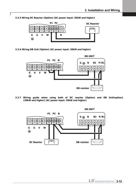
- Page 26 and 27: 3. Installation and Wiring ④ Crim
- Page 30 and 31: 3.4.2 Control circuit terminal arra
- Page 32 and 33: Item Name Function Description Enco
- Page 34 and 35: 3.4.4 Wiring the control circuit te
- Page 36 and 37: 3. Installation and Wiring 3.4.8 An
- Page 38 and 39: � SV900 ~ 2200iV5(Press) (for AC/
- Page 40 and 41: 4.2 Keypad LCD Display 4.2.1 LCD St
- Page 42 and 43: 4.4 Data Groups 4. Trial Operation
- Page 44 and 45: 4. Trial Operation 4.5 Auto-Tuning
- Page 46 and 47: PAR▶ Auto tuning 24 None PAR▶ A
- Page 48 and 49: 4.6 Pulse Encoder Check 4.6.1 The d
- Page 50 and 51: ② High Speed Operation 4. Trial O
- Page 52 and 53: 4.8.4 FX / RX operation 1) FX Opera
- Page 54 and 55: Operation Analog Voltage Input(AI1)
- Page 56 and 57: 5.2 Digital DIO Group (DIO_[][]) CO
- Page 58 and 59: 5.3 Parameter group (PAR_[][]) 5. F
- Page 60 and 61: Code No. Comm. Addr FUN_55 7437 FUN
- Page 62 and 63: 5.6. User group (USR_[][]) Code No.
- Page 64 and 65: 5.8. Analog AIO Group (AIO_[][]) Co
- Page 66 and 67: Code No. Comm. Addr AIO_34 7722 AIO
- Page 68 and 69: Code No. Comm. Addr AIO_74 774A AIO
- Page 70 and 71: Code Parameter name LCD display Uni
- Page 72 and 73: 6. Function Description No Trip inf
- Page 74 and 75: 1.1) Speed-L 1.2) Speed-M 1.3) Spee
- Page 76 and 77: 6. Function Description (MOP Save e
- Page 78 and 79:
1.10) Main Drive 6. Function Descri
- Page 80 and 81:
1.14) 3-Wire operation 6. Function
- Page 82 and 83:
CON_20 Terminal 1.19) Timer input 6
- Page 84 and 85:
1.25) Spd/Trq Sel (Speed/Torque Con
- Page 86 and 87:
2.1) Not used It is set unless mult
- Page 88 and 89:
2.8) Timer out 6. Function Descript
- Page 90 and 91:
6. Function Description Code Displa
- Page 92 and 93:
6.3 Parameter Group (PAR_[][]) 6.3.
- Page 94 and 95:
6.3.3 Motor parameters setting 1) P
- Page 96 and 97:
6. Function Description When encode
- Page 98 and 99:
2) Rotational auto-tuning 2.1) Prec
- Page 100 and 101:
3) Standstill auto tuning 3.1) Prec
- Page 102 and 103:
4) Motor parameters The following p
- Page 104 and 105:
6.4 Function group (FUN_[][]) 6.4.1
- Page 106 and 107:
6. Function Description operation c
- Page 108 and 109:
(Example) Programming P1, P2 as Xce
- Page 110 and 111:
� Calculation 1 � Calculation 2
- Page 112 and 113:
6.4.6 Electronic thermal (motor I T
- Page 114 and 115:
2) Setting range and factory settin
- Page 116 and 117:
6.4.10 Restart after fault reset 1)
- Page 118 and 119:
6.4.13 Brake opening and closing se
- Page 120 and 121:
6.4.14 Battery-operated (Battery Ru
- Page 122 and 123:
6.5 Control Group (CON_[][]) 6.5.1
- Page 124 and 125:
6. Function Description Code LCD di
- Page 126 and 127:
6. Function Description The definit
- Page 128 and 129:
6. Function Description Draw refere
- Page 130 and 131:
Droop Control Calculation Example
- Page 132 and 133:
6. Function Description Code LCD di
- Page 134 and 135:
9) Torque Current reference 6. Func
- Page 136 and 137:
6.6 User Group (USR_[][]) 6. Functi
- Page 138 and 139:
6.7 2nd Function Group (2nd_[][]) 6
- Page 140 and 141:
6.8 Analog AIO Group (AIO_[][]) 6.8
- Page 142 and 143:
6. Function Description the analog
- Page 144 and 145:
analog input Speed set 100% Initial
- Page 146 and 147:
6. Function Description The other m
- Page 148 and 149:
Multi-function analog output settin
- Page 150 and 151:
7.2 Loader Display in WEB Control M
- Page 152 and 153:
7.4.4 Diameter Initialization Funct
- Page 154 and 155:
7.4.8 Minimum Diameter Setting (Com
- Page 156 and 157:
7. WEB Control Application Figure 1
- Page 158 and 159:
③ Tension Reference Input Setting
- Page 160 and 161:
7.5.2 Digital Input/Output Group (D
- Page 162 and 163:
7. WEB Control Application 2) Multi
- Page 164 and 165:
7.6 Function Code of WEB Applicatio
- Page 166 and 167:
7.7 WEB Group Function 7.7.1 Jump c
- Page 168 and 169:
② Initialization of Core by Analo
- Page 170 and 171:
7. WEB Control Application computat
- Page 172 and 173:
Function Code 7. WEB Control Applic
- Page 174 and 175:
7. WEB Control Application Unwind/U
- Page 176 and 177:
7. WEB Control Application value of
- Page 178 and 179:
Tension Command where Ramp Time is
- Page 180 and 181:
I controller 7) WEB_34 PIDGain RAMP
- Page 182 and 183:
7. WEB Control Application 200[%].
- Page 184 and 185:
PID Type Block Diagram 19) WEB_46 P
- Page 186 and 187:
7.7.9 WEB Break Setting 1) WEB_48 W
- Page 188 and 189:
7. WEB Control Application roll spe
- Page 190 and 191:
TensionDisable(P1 ~ P7) 0 Splicing
- Page 192 and 193:
3) Megger test 8. Inspection and Re
- Page 194 and 195:
Protective function IGBT Short *1)
- Page 196 and 197:
9.4.2 Check list before installatio
- Page 198 and 199:
9. Troubleshooting and Maintenance
- Page 200 and 201:
hunting. ① Check the motor wiring
- Page 202 and 203:
14) Motor input current is too larg
- Page 204 and 205:
10.1.2 Wiring guide for encoder div
- Page 206 and 207:
Chapter 11 - Accessories 11.1 MCCB(
- Page 208 and 209:
11.3 The Selection of Braking Resis
- Page 210 and 211:
11.3.5 Braking resistor for braking
- Page 212 and 213:
� SV055, 075, 110, 150, 185, 220i
- Page 214 and 215:
12. Demensions � SV900, 1100, 132
- Page 216 and 217:
� SV2800, 3150, 3750iV5-4 12. Dem
- Page 218 and 219:
Setpoint setting(AI0:AI1) * AI2 ~ A
- Page 220 and 221:
Motor Max Speed Speed Ref FUN_04 Sp
- Page 222 and 223:
13. Control Block Diagram 13-6
- Page 224 and 225:
Speed Control Section Positive Torq
- Page 226 and 227:
Field Weakening Flux Ref. (%) Motor
- Page 228 and 229:
Vas Vbs PWM Dead Time Comp Vcs Volt
- Page 230 and 231:
ADDITIONAL UL MARKING Additional UL
- Page 232 and 233:
EMI / RFI POWER LINE FILTERS LS inv
- Page 234 and 235:
iV5 series / Standard Filters INVER
- Page 236 and 237:
` Maker LS Industrial Systems Co.,