LG_iV5_Manual_EN.pdf(4.61 MB) - Valiadis
LG_iV5_Manual_EN.pdf(4.61 MB) - Valiadis
LG_iV5_Manual_EN.pdf(4.61 MB) - Valiadis

You also want an ePaper? Increase the reach of your titles
YUMPU automatically turns print PDFs into web optimized ePapers that Google loves.
6. Function Description<br />
the analog input value that is under voltage 2[V], or current 4[mA] that is fed into analog input terminal will not be<br />
recognized.<br />
AIO_04 Ai1 Out Y1 sets the min. level of analog input voltage or current that inverter actually recognizes. For example,<br />
if you set AIO_03 Ai1 In X1 as 0[%] and set AIO_04 Ai1 Out Y1 as 20[%] and then, you feed into analog input<br />
terminal voltage 2[V] or current 4[mA], when the actual analog input voltage or current that inverter recognizes is 0,<br />
inverter recognizes as 20[%].<br />
AIO_15 Ai1 In X2 displays the analog input voltage or analog max. input current that inverter recognize as % unit.<br />
For example, if you set AIO_05 Ai1 In X2 as 50[%], when the actual voltage or current that is fed into analog input<br />
terminal is more than 5[V] or 10[mA], inverter recognizes it as max. analog input value.<br />
AIO_06 Ai1 Out Y2 sets the max. level of analog input voltage or current that inverter actually recognizes.<br />
For example, if you set AIO_05 Ai1 In X2 as 100[%] and AIO_06 Ai1 Out Y2 as 50[%], although the voltage 10[V] or<br />
the current 20[mA] is actually fed into analog input terminal, inverter recognizes the final analog input value as 50[%].<br />
If you set as above and the rated speed is 1800[rpm], you cannot set more than 900[rpm] although you feed 10[V] into<br />
analog input terminal<br />
.<br />
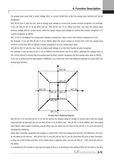
Analog input Mapping diagram<br />
AIO_03 Ai1 In X1 and AIO_05 Ai1 In X2 are for setting the allowed range of voltage of current that is fed into analog<br />
input terminal, so generally you can set AIO_03 Ai1 In X1 as 0[%], and AIO_05 Ai1 In X2 as 100[%]. But, the analog<br />
input device make happen Chattering around 0[%], you can adjust the set value of AIO_03 Ai1 In X1 up to the level of<br />
escaping the Chattering.<br />
When Main Controller recognizes the voltage or current that is fed into analog input terminal, the difference can occur<br />
by the detail of I/O devices. . AIO_04 Ai1 Out Y1 and AIO_06 Ai1 Out Y2 are for correcting this error in Main Controller,<br />
so they are a kind of Bias and Gain. If the analog input is negative value, you can set AIO_07 ~ AIO_10 as the same as<br />
the above.<br />
AIO_09<br />
AIO_07<br />
AIO_08<br />
AIO_10<br />
AIO_06<br />
AIO_04<br />
AIO_03<br />
AIO_05<br />
It is possible for <strong>iV5</strong> inverter to input also the upper limit of 2, 4 according to the setting of AIO_02 Ai1 Source, not only<br />
6-74