Tankless Water Heater Service Manual - Rinnai
Tankless Water Heater Service Manual - Rinnai
Tankless Water Heater Service Manual - Rinnai

You also want an ePaper? Increase the reach of your titles
YUMPU automatically turns print PDFs into web optimized ePapers that Google loves.
<strong>Tankless</strong> <strong>Water</strong> <strong>Heater</strong><br />
<strong>Service</strong> <strong>Manual</strong><br />
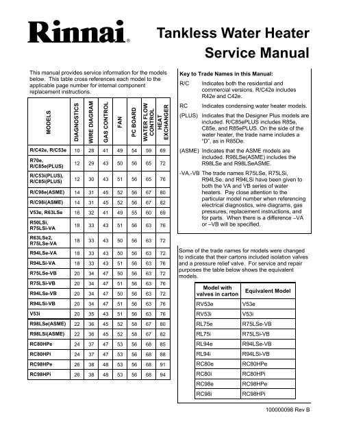
This manual provides service information for the models<br />
below. This table cross references each model to the<br />
applicable page number for internal component<br />
replacement instructions.<br />
MODELS<br />
R/C42e, R/C53e 10 28 41 49 54 59 69<br />
R70e,<br />
R/C85e(PLUS)<br />
R/C53i(PLUS),<br />
R/C85i(PLUS)<br />
DIAGNOSTICS<br />
WIRE DIAGRAM<br />
GAS CONTROL<br />
FAN<br />
PC BOARD<br />
WATER FLOW<br />
CONTROL<br />
HEAT<br />
EXCHANGER<br />
12 29 43 50 56 65 72<br />
12 30 43 51 56 65 76<br />
R/C98e(ASME) 14 31 45 52 56 67 80<br />
R/C98i(ASME) 14 31 45 52 56 67 82<br />
V53e, R63LSe 16 32 41 49 55 60 69<br />
R50LSi,<br />
R75LSi-VA<br />
18 33 43 51 56 63 76<br />
R63LSe2,<br />
R75LSe-VA<br />
18 33 43 50 56 63 72<br />
R94LSe-VA 18 33 43 50 56 63 72<br />
R94LSi-VA 18 33 43 51 56 63 76<br />
R75LSe-VB 20 34 47 50 56 63 72<br />
R75LSi-VB 20 34 47 51 56 63 76<br />
R94LSe-VB 20 34 47 50 56 63 72<br />
R94LSi-VB 20 34 47 51 56 63 76<br />
V53i 20 35 43 51 56 63 76<br />
R98LSe(ASME) 22 36 45 52 58 67 80<br />
R98LSi(ASME) 22 36 45 52 58 67 82<br />
RC80HPe 24 37 47 53 56 68 85<br />
RC80HPi 24 37 47 53 56 68 88<br />
RC98HPe 26 38 48 53 56 68 91<br />
RC98HPi 26 38 48 53 56 68 94<br />
Key to Trade Names in this <strong>Manual</strong>:<br />
R/C Indicates both the residential and<br />
commercial versions. R/C42e includes<br />
R42e and C42e.<br />
RC Indicates condensing water heater models.<br />
(PLUS) Indicates that the Designer Plus models are<br />
included. R/C85ePLUS includes R85e,<br />
C85e, and R85ePLUS. On the side of the<br />
water heater, the trade name includes a<br />
“D”, as in R85De.<br />
(ASME) Indicates that the ASME models are<br />
included. R98LSe(ASME) includes the<br />
R98LSe and R98LSeASME.<br />
-VA,-VB The trade names R75LSe, R75LSi,<br />
R94LSe, and R94LSi have been given to<br />
both the VA and VB series of water<br />
heaters. Pay close attention to the<br />
particular model number when referencing<br />
electrical diagnostics, wire diagrams, gas<br />
pressures, replacement instructions, and<br />
for parts. When there is a difference –VA<br />
or –VB will be specified.<br />
Some of the trade names for models were changed<br />
to indicate that their cartons included isolation valves<br />
and a pressure relief valve. For service and repair<br />
purposes the table below shows the equivalent<br />
models.<br />
Model with<br />
valves in carton<br />
RV53e<br />
RV53i<br />
RL75e<br />
RL75i<br />
RL94e<br />
RL94i<br />
RC80e<br />
RC80i<br />
RC98e<br />
RC98i<br />
Equivalent Model<br />
V53e<br />
V53i<br />
R75LSe-VB<br />
R75LSi-VB<br />
R94LSe-VB<br />
R94LSi-VB<br />
RC80HPe<br />
RC80HPi<br />
RC98HPe<br />
RC98HPi<br />
100000098 Rev B
Table of Contents<br />
General Information .................................................... 3<br />
Specifications .......................................................... 4-6<br />
Schematic Diagrams ............................................... 7-9<br />
Diagnostic Codes .................................................. 8-10<br />
Electrical Diagnostic Points<br />
R/C42e, R/C53e, ................................................. 10, 11<br />
R70e, R/C85e(PLUS),<br />
R/C53i(PLUS), R/C85i(PLUS) ............................. 12, 13<br />
R/C98e(ASME), R/C98i(ASME) ........................... 14, 15<br />
V53e, R63LSe ...................................................... 16, 17<br />
R50LSi, R63LSe2, R75LSe-VA, R75LSi-VA,<br />
R94LSe-VA, R94LSi-VA ...................................... 18, 19<br />
V53i, R75LSe-VB, R75LSi-VB,<br />
R94LSe-VB, R94LSi-VB ...................................... 20, 21<br />
R98LSe(ASME), R98LSi(ASME) ......................... 22, 23<br />
RC80HPe, RC80HPi ............................................ 24, 25<br />
RC98HPe, RC98HPi ............................................ 26, 27<br />
Wire Diagrams<br />
R/C42e, R/C53e .......................................................... 28<br />
R70e, R/C85e(PLUS) .................................................. 29<br />
R/C53i(PLUS), R/C85i(PLUS) ..................................... 30<br />
R/C98e(ASME), R/C98i(ASME) .................................. 31<br />
V53e, R63LSe ............................................................. 32<br />
R50LSi, R63LSe2, R75LSe-VA, R75LSi-VA,<br />
R94LSe-VA, R94LSi-VA ............................................. 33<br />
R75LSe-VB, R75LSi-VB, R94LSe-VB, R94LSi-VB .... 34<br />
V53i ............................................................................. 35<br />
R98LSe(ASME), R98LSi(ASME) ................................ 36<br />
RC80HPe, RC80HPi ................................................... 37<br />
RC98HPe, RC98HPi ................................................... 38<br />
Flushing the Heat Exchanger ................................... 39<br />
<strong>Manual</strong> Draining of the <strong>Water</strong> <strong>Heater</strong> ...................... 40<br />
Gas Control Assembly<br />
R/C42e, R/C53e, V53e, R63LSe ......................... 41, 42<br />
R/C53i(PLUS), R70e, R/C85e(PLUS), R/C85i(PLUS),<br />
R50LSi, V53i, R63LSe2, R75LSe-VA, R75LSi-VA,<br />
R94LSe-VA, R94LSi-VA ...................................... 43, 44<br />
R/C98e(ASME), R/C98i(ASME),<br />
R98LSe(ASME), R98LSi(ASME) ......................... 45, 46<br />
RC80HPe, RC80HPi, R75LSe-VB, R75LSi-VB,<br />
R94LSe-VB, R94LSi-VB ............................................. 47<br />
RC98HPe, RC98HPi ................................................... 48<br />
Fan<br />
R/C42e, R/C53e, V53e, R63LSe ................................ 49<br />
R70e, R/C85e(PLUS), R63LSe2,<br />
R75LSe, R94LSe........................................................ 50<br />
R/C53i(PLUS), R/C85i(PLUS), R50LSi,<br />
V53i, R75LSi, R94LSi ................................................. 51<br />
R/C98e(ASME), R/C98i(ASME),<br />
R98LSe(ASME), R98LSi(ASME) ............................... 52<br />
RC80HPe, RC80HPi, RC98HPe, RC98HPi ............... 53<br />
PC Board<br />
R/C42e, R/C53e ......................................................... 54<br />
V53e, R63LSe ............................................................ 55<br />
R/C53i(PLUS), R70e, R/C85e(PLUS),<br />
R/C85i(PLUS), R50LSi, R63LSe2, V53i,<br />
R75LSe, R75LSi, R94LSe, R94LSi,<br />
RC80HPe, RC80HPi, RC98HPe, RC98HPi .......... 56-57<br />
R/C98e(ASME), R/C98i(ASME),<br />
R98LSe(ASME), R98LSi(ASME) ............................... 58<br />
<strong>Water</strong> Flow Control Assembly<br />
R/C42e, R/C53e ................................................... 59, 60<br />
V53e, R63LSe ...................................................... 61, 62<br />
R/C53i, R70e, R50LSi, R63LSe2, V53i,<br />
R75LSe, R75LSi ................................................... 63, 64<br />
R/C85e(PLUS), R/C85i(PLUS),<br />
R94LSe, R94LSi ................................................... 65, 66<br />
R/C98e(ASME), R/C98i(ASME),<br />
R98LSe(ASME), R98LSi(ASME) ............................... 67<br />
RC80HPe, RC80HPi, RC98HPe, RC98HPi ............... 68<br />
Heat Exchanger<br />
R/C42e, R/C53e, V53e, R63LSe ........................... 69-71<br />
R70e, R/C85e(PLUS), R63LSe2,<br />
R75LSe, R94LSe................................................... 72-75<br />
R/C53i(PLUS), R/C85i(PLUS), V53i,<br />
R50LSi, R75LSi, R94LSi ....................................... 76-79<br />
R/C98e(ASME), R98LSe(ASME) .......................... 80-81<br />
R/C98i(ASME), R98LSi(ASME) ............................ 82-84<br />
RC80HPe .............................................................. 85-87<br />
RC80HPi ................................................................ 88-90<br />
RC98HPe .............................................................. 91-93<br />
RC98HPi ................................................................ 94-96<br />
Gas Pressure Setting Procedure ....................... 97-98<br />
Manifold Pressure Settings .............................. 99-105<br />
Dip Switches .................................................... 106-108<br />
<strong>Rinnai</strong> <strong>Water</strong> <strong>Heater</strong> <strong>Service</strong> <strong>Manual</strong> 2 100000098 Rev B
General Information<br />
Safety Definitions<br />
This is the safety alert symbol. This symbol alerts you to potential hazards that can kill or hurt you and<br />
others.<br />
DANGER<br />
WARNING<br />
CAUTION<br />
Indicates an imminently hazardous situation which, if not avoided, will result in death or<br />
serious injury.<br />
Indicates a potentially hazardous situation which, if not avoided, could result in death or<br />
serious injury.<br />
Indicates a potentially hazardous situation which, if not avoided, could result in minor or<br />
moderate injury. It may also be used to alert against unsafe practices.<br />
Using this <strong>Manual</strong><br />
Repairs should be performed by a qualified service technician.<br />
The following information can be referenced for additional information.<br />
• Operation and Installation <strong>Manual</strong><br />
• Hot <strong>Water</strong> System Design <strong>Manual</strong><br />
• Technical Sheets<br />
• Technical Bulletins<br />
Technical Support<br />
Technicians are available to assist in servicing issues. Contact <strong>Rinnai</strong> Technical <strong>Service</strong>s at 1-800-621-9419.<br />
Recommended Tools<br />
• Volt/Ohm/Amp meter with test probes<br />
• Digital manometer or U tube type manometer with 14 inch water column (W.C.) scale, a hose and two 1/8 inch<br />
taps<br />
• assorted wrenches including a 3/16 Allen wrench<br />
• assorted screw drivers<br />
• leak solution or leak detector<br />
• Teflon tape<br />
WARNING<br />
There are a number of live tests that are required when fault finding this product. Extreme care should be used at<br />
all times to avoid contact with energized components inside the water heater. Before checking for resistance<br />
readings disconnect the power source to the unit and isolate the item from the circuit (unplug it).<br />
CAUTION<br />
Label all wires prior to disconnection when<br />
servicing controls. Wiring errors can cause<br />
improper and dangerous operation.<br />
If any of the original wire as supplied with the appliance must<br />
be replaced, it must be replaced with type 18 AWG wire or its<br />
equivalent.<br />
<strong>Rinnai</strong> <strong>Water</strong> <strong>Heater</strong> <strong>Service</strong> <strong>Manual</strong> 3 100000098 Rev B
Specifications<br />
V Series - Commercial - Outdoor<br />
Trade Name Model Max. BTU Min. BTU Max Flow [1]<br />
gal/min (liters/min)<br />
Temperature Range<br />
C42e REU-V1616WC 120,000<br />
17,100 (NG)<br />
17,800 (LP) 4.2 (16) 120 - 185 ºF (49-85 ºC)<br />
C53e REU-V2020WC 150,000<br />
19,000 (NG)<br />
20,200 (LP) 5.3 (20) 120 - 185 ºF (49-85 ºC)<br />
C85e REU-V2532WC 199,000 15,000 8.5 (32) 98 - 185 ºF (37-85 ºC)<br />
C85ePLUS REU-V2532WCD 199,000 15,000 8.5 (32) 98 - 185 ºF (37-85 ºC)<br />
C98e REU-V3237WC 237,000 19,000 9.8 (37) 98 - 185 ºF (37-85 ºC)<br />
C98eASME REU-V3237WC-ASME 237,000 19,000 9.8 (37) 98 - 185 ºF (37-85 ºC)<br />
V Series - Commercial - Indoor<br />
Trade Name Model Max. BTU Min. BTU Max Flow [1] Temperature Range<br />
gal/min (liters/min)<br />
C53i REU-V2520FFUC 180,000 15,000 5.3 (20) 120 - 185 ºF (49-85 ºC)<br />
C53iPLUS REU-V2520FFUCD 180,000 15,000 5.3 (20) 120 - 185 ºF (49-85 ºC)<br />
C85i REU-V2532FFUC 180,000 15,000 8.5 (32) 98 - 185 ºF (37-85 ºC)<br />
C85iPLUS REU-V2532FFUCD 180,000 15,000 8.5 (32) 98 - 185 ºF (37-85 ºC)<br />
C98i REU-V3237FFUC 237,000 19,000 9.8 (37) 98 - 185 ºF (37-85 ºC)<br />
C98iASME REU-V3237FFUC-ASME 237,000 19,000 9.8 (37) 98 - 185 ºF (37-85 ºC)<br />
V Series - Residential - Outdoor<br />
Trade Name Model Max. BTU Min. BTU Max Flow [1] Temperature Range<br />
gal/min (liters/min)<br />
17,100 (NG)<br />
R42e REU-V1616W 120,000 17,800 (LP) 4.2 (16) 98 - 140 ºF (37-60 ºC)<br />
R53e REU-V2020W 150,000<br />
19,000 (NG)<br />
20,200 (LP) 5.3 (20) 98 - 140 ºF (37-60 ºC)<br />
R70e REU-V2526W 199,000 15,000 7.0 (26) 98 - 140 ºF (37-60 ºC)<br />
R85e REU-V2532W 199,000 15,000 8.5 (32) 98 - 140 ºF (37-60 ºC)<br />
R85ePLUS REU-V2532WD 199,000 15,000 8.5 (32) 98 - 140 ºF (37-60 ºC)<br />
R98e REU-V3237W 237,000 19,000 9.8 (37) 98 - 140 ºF (37-60 ºC)<br />
R98eASME REU-V3237W-ASME 237,000 19,000 9.8 (37) 98 - 140 ºF (37-60 ºC)<br />
V Series - Residential - Indoor<br />
Trade Name Model Max. BTU Min. BTU Max Flow [1] Temperature Range<br />
gal/min (liters/min)<br />
R53i REU-V2520FFU 180,000 15,000 5.3 (20) 98 - 140 ºF (37-60 ºC)<br />
R53iPLUS REU-V2520FFU 180,000 15,000 5.3 (20) 98 - 140 ºF (37-60 ºC)<br />
R85i REU-V2532FFU 180,000 15,000 8.5 (32) 98 - 140 ºF (37-60 ºC)<br />
R85iPLUS REU-V2532FFUD 180,000 15,000 8.5 (32) 98 - 140 ºF (37-60 ºC)<br />
R98i REU-V3237FFU 237,000 19,000 9.8 (37) 98 - 140 ºF (37-60 ºC)<br />
R98iASME REU-V3237FFU-ASME 237,000 19,000 9.8 (37) 98 - 140 ºF (37-60 ºC)<br />
[1] Minimum activation flow is approximately 0.6 gallons/minute (2.3 liters/min)<br />
<strong>Rinnai</strong> <strong>Water</strong> <strong>Heater</strong> <strong>Service</strong> <strong>Manual</strong> 4 100000098 Rev B
Specifications<br />
VA Series (LS Series) - Residential or Commercial - Outdoor<br />
Trade Name Model Max. BTU Min. BTU Max Flow [1]<br />
gal/min (liters/min)<br />
R63LSe REU-VA2024WD-US 150,000<br />
21,500 (NG)<br />
20,600 (LP)<br />
6.3 (24)<br />
R63LSe2 REU-VA2024WD(A)-US 150,000 15,000 6.3 (24)<br />
R75LSe REU-VA2528WD-US 199,000 15,000 7.5 (28)<br />
R75LSe<br />
REU-VA2528WD(A)-US<br />
REU-VA2528WD(A)-UC<br />
180,000 15,000 7.5 (28)<br />
R94LSe<br />
REU-VA2535WD-US<br />
REU-VA2535WD-UC<br />
199,000 15,000 9.4 (35)<br />
R98LSe REU-VA3237W-US 237,000 19,000 9.8 (37)<br />
R98LSeASME REU-VA3237W-ASME 237,000 19,000 9.8 (37)<br />
Temperature Range<br />
98 - 140 ºF (37-60 ºC) [2]<br />
98 - 140 ºF (37-60 ºC) [3]<br />
VA Series (LS Series) - Residential or Commercial - Indoor<br />
Trade Name Model Max. BTU Min. BTU Max Flow [1]<br />
gal/min (liters/min)<br />
R50LSi REU-VA2019FFUD-US 150,000 15,000 5.0 (19)<br />
R75LSi REU-VA2528FFUD-US 199,000 15,000 7.5 (28)<br />
R75LSi<br />
R94LSi<br />
REU-VA2528FFUD(A)-<br />
US<br />
REU-VA2528FFUD(A)-<br />
UC<br />
REU-VA2535FFUD-US<br />
REU-VA2535FFUD-UC<br />
180,000 15,000 7.5 (28)<br />
199,000 (NG)<br />
190,000 (LPG)<br />
15,000 9.4 (35)<br />
R98LSi REU-VA3237FFU-US 237,000 19,000 9.8 (37)<br />
R98LSiASME REU-VA3237FFU-ASME 237,000 19,000 9.8 (37)<br />
Temperature Range<br />
98 - 140 ºF (37-60 ºC) [2]<br />
98 - 140 ºF (37-60 ºC) [3]<br />
VA Series - Residential - Outdoor<br />
Trade Name Model Max. BTU Min. BTU Max Flow [1]<br />
gal/min (liters/min)<br />
V53e REU-VAM1620W-US 120,000<br />
Temperature Range<br />
19,000 (NG)<br />
20,200 (LP) 5.3 (20) 98 - 140 ºF (37-60 ºC)<br />
[1] Minimum activation flow is approximately 0.6 gallons/minute (2.3 liters/min)<br />
[2] Max temperature is 160 ºF (71 ºC) with the MCC-91 controller for commercial and hydronic applications only.<br />
[3] Max temperature is 185 ºF (85 ºC) with the MCC-91 controller for commercial and hydronic applications only.<br />
<strong>Rinnai</strong> <strong>Water</strong> <strong>Heater</strong> <strong>Service</strong> <strong>Manual</strong> 5 100000098 Rev B
Specifications<br />
VB Series (LS Series) - Residential or Commercial - Outdoor<br />
Trade Name Model Max. BTU Min. BTU Max Flow [1]<br />
gal/min (liters/min)<br />
R75LSe,<br />
RL75e<br />
R94LSe,<br />
RL94e<br />
REU-VB2528WD-US 180,000<br />
REU-VB2735WD-US 199,000<br />
9,900 (NG)<br />
10,300 (LPG)<br />
9,900 (NG)<br />
10,300 (LPG)<br />
VB Series (LS Series) - Residential or Commercial - Indoor<br />
Temperature Range<br />
7.5 (28) 98 - 140 ºF (37-60 ºC) [2]<br />
9.4 (35) 98 - 140 ºF (37-60 ºC) [3]<br />
Trade Name Model Max. BTU Min. BTU Max Flow [1]<br />
gal/min (liters/min)<br />
Temperature Range<br />
R75LSi, RL75i REU-VB2528FFUD-US 180,000<br />
R94LSi, RL94i REU-VB2735FFUD-US<br />
199,000 (NG)<br />
190,000 (LPG)<br />
9,900 (NG)<br />
10,300 (LPG)<br />
9,900 (NG)<br />
10,300 (LPG)<br />
7.5 (28) 98 - 140 ºF (37-60 ºC) [2]<br />
9.4 (35) 98 - 140 ºF (37-60 ºC) [3]<br />
VB Series - Residential - Indoor<br />
Trade Name Model Max. BTU Min. BTU Max Flow [4]<br />
gal/min (liters/min)<br />
Temperature Range<br />
V53i, RV53i REU-VB2020FFU-US 150,000 15,000 5.3 (20) 98 - 140 ºF (37-60 ºC)<br />
Condensing Series - Residential or Commercial - Outdoor<br />
Trade Name Model Max. BTU Min. BTU Max Flow [1]<br />
gal/min (liters/min)<br />
RC80HPe,<br />
RC80e<br />
RC98HPe,<br />
RC98e<br />
REU-KA2530WD-US 157,000<br />
REU-KA3237WD-US 199,000<br />
9,500 (NG)<br />
10,300 (LPG)<br />
9,500 (NG)<br />
10,300 (LPG)<br />
8.0 (30)<br />
9.8 (37)<br />
Temperature Range<br />
98 - 140 ºF (37-60 ºC) [3]<br />
Condensing Series - Residential or Commercial - Indoor<br />
Trade Name Model Max. BTU Min. BTU Max Flow [1]<br />
gal/min (liters/min)<br />
Temperature Range<br />
RC80HPi,<br />
RC80i<br />
RC98HPi,<br />
RC98i<br />
REU-KA2530FFUD-US 157,000<br />
REU-KA3237FFUD-US 199,000<br />
9,500 (NG)<br />
10,300 (LPG)<br />
9,500 (NG)<br />
10,300 (LPG)<br />
8.0 (30)<br />
9.8 (37)<br />
98 - 140 ºF (37-60 ºC) [3]<br />
[1] Minimum activation flow is approximately 0.4 gallons/minute (1.5 liters/min); minimum flow is approximately<br />
0.26 gallons/minute (1 liter/min).<br />
[2] Max temperature is 160 ºF (71 ºC) with the MCC-91 controller for commercial and hydronic applications only.<br />
[3] Max temperature is 185 ºF (85 ºC) with the MCC-91 controller for commercial and hydronic applications only.<br />
[4] Minimum activation flow is approximately 0.6 gallons/minute (2.3 liters/min).<br />
<strong>Rinnai</strong> <strong>Water</strong> <strong>Heater</strong> <strong>Service</strong> <strong>Manual</strong> 6 100000098 Rev B
Diagnostic Codes<br />
The <strong>Rinnai</strong> water heater has the ability to check its own operation continuously. If a fault occurs, an error code<br />
will flash on the display of the remote controller. This assists with diagnosing the fault and may enable you to<br />
overcome a problem without a service call.<br />
WARNING<br />
Some of the checks below may need to be done by a qualified service technician. Call a<br />
service technician for any remedy that involves gas or electricity. Call a service<br />
technician if you have any doubt or reservation about performing the remedy yourself.<br />
Accessing Operating Information<br />
Models MC-91 and MCC-91<br />
To display the most recent error codes press and hold the “On/Off” button for 2 seconds. While holding the “On/<br />
Off” button press the ▲ button. The last 9 error codes will flash one after the other. To exit this mode press the<br />
“On/Off” and ▲ button as before.<br />
To display the water flow through the water heater press and hold the ▲ button for 2 seconds and without<br />
releasing the ▲ button press the “On/Off” button.<br />
To display the outlet water temperature press and hold the ▼ button for 2 seconds and without releasing the ▼<br />
button press the “On/Off” button.<br />
Operation<br />
1. <strong>Water</strong> Flow Begins.<br />
• <strong>Water</strong> Flow Sensor sends pulses to the PC<br />
Board.<br />
• PC Board senses flow.<br />
• Firing Sequence begins when the flow exceeds<br />
the minimum activation flow rate.<br />
2. Firing Sequence.<br />
• PC Board monitors inlet/outlet water<br />
temperature, temperature set point, and water<br />
flow rate.<br />
• Combustion fan energized. Purges combustion<br />
chamber.<br />
• Spark igniter begins sparking.<br />
• Gas control valve opens to minimum fire rate.<br />
• Flame rod(s) proves ignition.<br />
• Spark igniter stops sparking.<br />
4. Shut-down Sequence.<br />
• Shut-down begins when the PC Board senses<br />
the minimum flow rate which is 0.26 - 0.5 gpm<br />
depending on model.<br />
• Gas control valve closes.<br />
• <strong>Water</strong> flow control valve resets to standby<br />
position.<br />
• Combustion fan runs for a short period of time<br />
at low speed.<br />
5. Standby Mode.<br />
• PC Board monitors water temperature and<br />
remote controls.<br />
• Freeze protection is activated as needed.<br />
3. Normal Operation.<br />
• PC Board monitors flame rod, fan motor<br />
frequency, outlet water temperature, controller<br />
temperature set point and water flow rate.<br />
• Gas control valve modulates gas input to<br />
required firing rate.<br />
• Combustion fan speed is adjusted for the<br />
required firing rate.<br />
• <strong>Water</strong> flow control valve is adjusted as needed.<br />
<strong>Rinnai</strong> <strong>Water</strong> <strong>Heater</strong> <strong>Service</strong> <strong>Manual</strong> 7 100000098 Rev B
Code Definition Remedy<br />
02 No burner operation during<br />
freeze protection mode<br />
ONLY FOR NON-<br />
CONDENSING MODELS<br />
03 Power interruption during Bath<br />
Fill (<strong>Water</strong> will not flow when<br />
power returns).<br />
10 Air Supply or Exhaust<br />
Blockage<br />
Diagnostic Codes<br />
<strong>Service</strong> Call<br />
Turn off all hot water taps. Press ON/OFF twice.<br />
Ensure <strong>Rinnai</strong> approved venting materials are being used.<br />
Check that nothing is blocking the flue inlet or exhaust.<br />
Check all vent components for proper connections.<br />
Ensure vent length is within limits.<br />
For non-condensing models, ensure condensation collar was installed correctly.<br />
Verify dip switches are set properly.<br />
Check fan for blockage.<br />
Check the fins in the heat exchanger.<br />
For condensing models, Burner Sensor Error (see code 31)<br />
11 No Ignition Check that the gas is turned on at the water heater, gas meter, or cylinder.<br />
Ensure gas type and pressure is correct.<br />
Ensure gas line, meter, and/or regulator is sized properly.<br />
Bleed all air from gas lines.<br />
Verify dip switches are set properly.<br />
Ensure appliance is properly grounded.<br />
Disconnect EZConnect or MSA controls to isolate the problem.<br />
Ensure igniter is operational.<br />
Check igniter wiring harness for damage.<br />
Check gas solenoid valves for open or short circuits.<br />
Remove burner cover and ensure all burners are properly seated.<br />
Remove burner plate and inspect burner surface for condensation or debris.<br />
If flame is visible, check the flame rod circuit.<br />
12 Flame Failure Check that the gas is turned on at the water heater and gas meter. Check for obstructions in<br />
the flue outlet.<br />
Ensure gas line, meter, and/or regulator is sized properly.<br />
Ensure gas type and pressure is correct.<br />
Bleed all air from gas lines.<br />
Ensure proper <strong>Rinnai</strong> venting material was installed.<br />
For non-condensing models, ensure condensation collar was installed properly.<br />
Ensure vent length is within limits.<br />
Verify dip switches are set properly.<br />
Ensure appliance is properly grounded.<br />
Disconnect keypad.<br />
Disconnect EZConnect or MSA controls to isolate the problem.<br />
Check power supply for loose connections.<br />
Check power supply for proper voltage and voltage drops.<br />
Ensure flame rod wire is connected.<br />
Ensure flame rod is in proper position (wire should connect at 6 o’clock position).<br />
Remove flame rod and check for carbon build-up; clean with sand paper or emery cloth.<br />
Disconnect and reconnect all wiring harnesses on unit and PC board.<br />
Check all components for electrical short.<br />
Check gas solenoid valves for open or short circuits.<br />
Remove burner plate and inspect burner surface for condensation or debris.<br />
Check the ground wire for the PC board.<br />
14 Thermal Fuse Check gas type of unit and ensure it matches gas type being used.<br />
Check for restrictions in air flow around unit and vent terminal.<br />
Check for low water flow in a circulating system causing short-cycling.<br />
Ensure dip switches are set to the proper position.<br />
Check for foreign materials in combustion chamber and/or exhaust piping.<br />
Check heat exchanger for cracks and/or separations.<br />
Check heat exchanger surface for hot spots which indicate blockage due to scale build-up.<br />
Refer to instructions in manual for flushing heat exchanger. Hard water must be treated<br />
to prevent scale build up or damage to the heat exchanger.<br />
Measure resistance of safety circuit.<br />
Ensure high fire and low fire manifold pressure is correct.<br />
Check for improper conversion of product.<br />
16 Over Temperature Warning Check for restrictions in the intake and exhaust system.<br />
Check for low water flow in a circulating system causing short-cycling.<br />
Check for foreign materials in combustion chamber and/or exhaust piping.<br />
Check for blockage in the heat exchanger.<br />
<strong>Rinnai</strong> <strong>Water</strong> <strong>Heater</strong> <strong>Service</strong> <strong>Manual</strong> 8 100000098 Rev B
Code Definition Remedy<br />
25 Condensate Trap Error<br />
ONLY FOR<br />
CONDENSING MODELS<br />
31 Burner Sensor Error<br />
ONLY FOR VB AND<br />
CONDENSING INDOOR<br />
MODELS<br />
32 Outgoing <strong>Water</strong><br />
Temperature Sensor<br />
33 Heat Exchanger Outgoing<br />
Temperature Sensor<br />
34 Combustion Air<br />
Temperature Sensor<br />
ONLY FOR INDOOR<br />
NON-CONDENSING<br />
MODELS (EXCEPT<br />
R98LSi)<br />
52 Modulating Solenoid<br />
Valve Signal Abnormal<br />
Condensate container is full.<br />
Check condensate drain for blockage.<br />
Replace condensate trap.<br />
Measure resistance of sensor.<br />
Replace sensor.<br />
Check sensor wiring for damage.<br />
Measure resistance of sensor.<br />
Clean sensor of scale build-up.<br />
Replace sensor.<br />
Check sensor wiring to be sure it has not been short circuited.<br />
Measure resistance of sensor.<br />
Clean sensor of scale build-up.<br />
Replace sensor.<br />
Check for restrictions in the intake and exhaust system.<br />
Check sensor wiring for damage.<br />
Measure resistance of sensor.<br />
Clean sensor of scale build-up.<br />
Check the fan blade to be sure it is tight on motor shaft and is in good condition.<br />
Replace sensor.<br />
Check modulating gas solenoid valve wiring harness for loose or damaged terminals.<br />
Measure resistance of valve coil.<br />
61 Combustion Fan Failure Ensure fan will turn freely.<br />
Check wiring harness to motor for damaged and/or loose connections.<br />
Measure resistance of motor winding.<br />
Check for proper voltage from PC board.<br />
65 <strong>Water</strong> Flow Control The water flow control valve has failed to close during the bath fill function. Immediately turn off<br />
the water and discontinue the bath fill function. Contact a state qualified or licensed contractor to<br />
service the appliance.<br />
70 Sensor Harness<br />
Connection<br />
ONLY FOR<br />
CONDENSING MODELS<br />
Check PC board switches (in the bank of 6 switches, #2 should be on for indoor models and off for<br />
outdoor models)<br />
Check the connection harness at the E connection on the PC board. Outdoor models should have<br />
2 orange cables at #7 and 8 positions. Indoor models should not have cables at these positions. If<br />
this is incorrect then replace the sensor harness.<br />
Replace PC board<br />
71 Solenoid Valve Circuit For non-condensing, check wiring harness to all solenoids for damage and/or loose connections.<br />
Measure resistance of each solenoid valve coil.<br />
For condensing, replace PC board.<br />
72 Flame Sensing Device Verify flame rod is touching flame when unit fires.<br />
Check all wiring to flame rod.<br />
Remove flame rod and check for carbon build-up; clean with sand paper or emery cloth.<br />
Check inside burner chamber for any foreign material blocking flame at flame rod.<br />
Measure micro amp output of sensor circuit with flame present.<br />
Replace flame rod.<br />
73 Burner Sensor Circuit<br />
ONLY FOR VB AND<br />
CONDENSING INDOOR<br />
MODELS<br />
LC Scale Build-up in Heat<br />
Exchanger (when<br />
checking maintenance<br />
code history, “00” is<br />
substituted for “LC”)<br />
No<br />
code<br />
Nothing happens when<br />
water flow is activated.<br />
Diagnostic Codes<br />
Check sensor wiring and PC board to be sure they have not been damaged.<br />
Replace sensor.<br />
Flush heat exchanger. Refer to instructions in manual. Hard water must be treated to prevent<br />
scale build up or damage to the heat exchanger.<br />
Replace heat exchanger.<br />
NOTE: The LC code is the only code that will allow the unit to keep running. The display will<br />
alternate between the LC code and the temperature setting. The controller will continue to beep.<br />
The LC code will reset if power is turned off and then on.<br />
On controller, verify if unit is sensing flow. If not then check the items below. If unit is<br />
sensing flow then check the heat exchanger and outlet thermistors.<br />
Clean inlet water supply filter.<br />
On new installations ensure hot and cold water lines are not reversed.<br />
Check for cold to hot cross over. Isolate circulating system if present. Turn off cold water to the<br />
unit, open pressure relief valve; if water continues to flow, there is bleed over in your plumbing.<br />
Verify you have at least the minimum flow rate required to fire unit.<br />
Verify turbine spins freely.<br />
Measure the resistance of the water flow control sensor.<br />
If the display is blank and clicking is coming from the unit, disconnect the water flow servo motor<br />
(RD, BL, BR, GY, YL). If the display come on then replace the water flow servo motor.<br />
<strong>Rinnai</strong> <strong>Water</strong> <strong>Heater</strong> <strong>Service</strong> <strong>Manual</strong> 9 100000098 Rev B
Electrical Diagnostic Points<br />
R/C42e, R/C53e<br />
Wire Color Voltage Resistance Connector No. Pin No.’s<br />
(TR) Transformer<br />
Black - White 90 - 100 VAC 51-63 ohms F2 1 ~ 2<br />
Blue - Brown 108 - 132 VAC 51-63 ohms F3 1 ~ 3<br />
(SV1, SV2, SV3, POV) Gas Valve and Modulating Solenoids<br />
(Main) Pink - Black<br />
E1 1 ~ 2<br />
(SV1) Black - Blue 80 - 100 VDC 1.7 - 2 K ohms<br />
E2 1 ~ 2<br />
(SV2) Black - Yellow E3 1 ~ 2<br />
(POV) Pink - Pink 2 - 15 VDC 67 - 81 ohms C2 1 ~ 2<br />
(M) <strong>Water</strong> Flow Servo<br />
Red - Blue 11 - 13 VDC 22 - 26 ohms B1 1 ~ 2<br />
Gray - Brown 4 - 6 VDC N/A B1 6 ~ 3<br />
Gray - Yellow N/A N/A B1 6 ~ 5<br />
Gray - Orange 11 - 14 VDC N/A B1 6 ~ 4<br />
NOTE: At the B connector on the PCB: gray wire turns to black, orange wire turns to red<br />
(QS) <strong>Water</strong> Flow Sensor<br />
Black - Red 11 - 13 VDC 5.5 - 6.2 K ohms B3 3 ~ 1<br />
Yellow - Black 4 - 7 VDC 1 - 1.4 mega ohms B3 2 ~ 3<br />
(IG) Ignition System<br />
Gray - Gray 90 - 100 VAC N/A F1 1 ~ 2<br />
(FM) Combustion Fan Motor<br />
Red - Black 6 - 45 VDC N/A A1 1 ~ 2<br />
White - Black 5 - 10 VDC 9.2 - 9.4 K ohms A1 2 ~ 4<br />
Yellow - Black 11 ~ 13 VDC 3.5 - 3.9 K ohms A1 2 ~ 3<br />
With the meter set on hertz scale, 60-350 hertz should be across the red and yellow wires at<br />
terminals 2 and 3.<br />
<strong>Rinnai</strong> <strong>Water</strong> <strong>Heater</strong> <strong>Service</strong> <strong>Manual</strong> 10 100000098 Rev B
Electrical Diagnostic Points<br />
R/C42e, R/C53e<br />
Wire Color Voltage Resistance Connector No. Pin No.’s<br />
Thermal Fuse / Overheat Switch<br />
Red - Red 12 VDC below 1 ohm B, C 6 (B) ~ 1 (C)<br />
Flame Rod<br />
Place one lead of the meter to the flame rod and the other to ground. Flame rod to ground should<br />
read 1 mega ohm with unit not running. With the unit running, 5-150 VAC should be read. If voltage<br />
range is incorrect then replace PC board. Set the meter to the μ amp scale and series the meter in<br />
line with the flame rod. Proper flame circuit should read 1 micro-amp or greater. If micro-amp range<br />
is incorrect then clean flame rod; replace flame rod if cleaning fails.<br />
Thermistors<br />
Check all thermistors by inserting meter leads into each end of the thermistor plug. Set the meter to<br />
the 20 K ohm scale and read resistance. Applying heat to the thermistor bulb should decrease the<br />
resistance. Applying ice to the thermistor bulb should increase the resistance. Typical resistance<br />
values are: 11.4-14 K ohm for 59°F; 6.4-7.8 K ohm for 86°F; 3.6-4.5 K ohm for 113°F; 2.2-2.7 K ohm<br />
for 140°F; 0.6-0.8 K ohm for 221°F<br />
Outgoing <strong>Water</strong> Thermistor<br />
White - White see above B4 1 ~ 2<br />
Heat Exchanger Temperature Thermistor<br />
White - White see above B5 1 ~ 2<br />
Surge Protector<br />
Blue - Brown 108 - 132 VAC N/A F4 1 ~ 2<br />
Blue - Brown 108 - 132 VAC N/A F3 1 ~ 3<br />
With the power off, check the continuity through the surge protector. Check by placing one meter<br />
lead on the top pin #1 and bottom pin #2. Check by placing one meter lead on the top pin #3 and<br />
bottom pin #1. If there is continuity across both sets of points, then the surge protector is good.<br />
Controller<br />
Terminals D1<br />
10 - 13 VDC<br />
digital<br />
1.5 - 1.9 K ohms D 1 ~ 3<br />
Frost Protection<br />
There are electrical heating elements mounted at different points to protect the water heater from<br />
freezing.<br />
heaters located on the hot water outlet line 26 - 30 ohms<br />
heater located on heat exchanger piping 81 - 86 ohms<br />
heater located on water flow sensor<br />
16 - 19 ohms<br />
Amp fuses<br />
There are two inline 3 amp glass fuses. Remove the fuse and check continuity through it. If there is<br />
continuity then the fuse is good.<br />
<strong>Rinnai</strong> <strong>Water</strong> <strong>Heater</strong> <strong>Service</strong> <strong>Manual</strong> 11 100000098 Rev B
Electrical Diagnostic Points<br />
R70e, R/C85e(PLUS),<br />
R/C53i(PLUS), R/C85i(PLUS)<br />
Wire Color Voltage Resistance Connector No. Pin No.’s<br />
(TR) Transformer<br />
Black - White 90 - 100 VAC 51-63 ohms F9 1 ~ 2<br />
Blue - Brown 108 - 132 VAC 51-63 ohms F7 1 ~ 3<br />
(SV1, SV2, SV3, POV) Gas Valve and Modulating Solenoids<br />
(Main) Pink - Black<br />
E1 1 ~ 2<br />
(SV1) Black - Yellow E2 1 ~ 2<br />
80 - 100 VDC 1.7 - 2 K ohms<br />
(SV2) Black - Blue E3 1 ~ 2<br />
(SV3) Black - Brown E4 1 ~ 2<br />
(POV) Pink - Pink 2 - 15 VDC 67 - 81 ohms C2 1 ~ 2<br />
(M) <strong>Water</strong> Flow Servo<br />
Red - Blue 11 - 13 VDC 22 - 26 ohms B1 outdoor 1 ~ 2<br />
Gray - Brown 4 - 6 VDC N/A models 6 ~ 3<br />
Gray - Yellow N/A N/A B2 indoor 6 ~ 5<br />
Gray - Orange 11 - 14 VDC N/A models 6 ~ 4<br />
NOTE: At the B connector on the PCB: gray wire turns to black, orange wire turns to red<br />
(QS) <strong>Water</strong> Flow Sensor<br />
Black - Red 11 - 13 VDC 5.5 - 6.2 K ohms B1 outdoor 1 ~ 3<br />
Yellow - Black 4 - 7 VDC 1 - 1.4 mega ohms<br />
models<br />
B2 indoor<br />
models<br />
2 ~ 3<br />
Bypass Flow Control (only on R/C85e, R/C85ePLUS, R/C85i, R/C85iPLUS)<br />
Brown - White<br />
1 ~ 5<br />
Orange - White 2 - 6 VDC<br />
G1 (plug between 2 ~ 5<br />
(unit in operating 15 - 35 K ohms<br />
Yellow - White bypass and PCB)<br />
mode)<br />
3 ~ 5<br />
Red - White/Ground 4 ~ 5<br />
(IG) Ignition System<br />
Gray - Gray 90 - 100 VAC N/A F8 1 ~ 2<br />
(FM) Combustion Fan Motor<br />
Red - Black 6 - 45 VDC N/A A1 1 ~ 2<br />
White - Black 5 - 10 VDC 9.2 - 9.4 K ohms A1 2 ~ 4<br />
Yellow - Black 11 ~ 13 VDC 3.5 - 3.9 K ohms A1 2 ~ 3<br />
With the meter set on hertz scale, 60-350 hertz should be across the red and yellow wires at<br />
terminals 2 and 3.<br />
<strong>Rinnai</strong> <strong>Water</strong> <strong>Heater</strong> <strong>Service</strong> <strong>Manual</strong> 12 100000098 Rev B
Electrical Diagnostic Points<br />
R70e, R/C85e(PLUS),<br />
R/C53i(PLUS), R/C85i(PLUS)<br />
Wire Color Voltage Resistance Connector No. Pin No.’s<br />
Thermal Fuse / Overheat Switch<br />
C3-B2 outdoor models<br />
Red - Red 12 VDC below 1 ohm<br />
1 ~ 1<br />
C3-B3 indoor models<br />
Flame Rod<br />
Place one lead of the meter to the flame rod and the other to ground. Flame rod to ground should read 1 mega<br />
ohm with unit not running. With the unit running, 5-150 VAC should be read. If voltage range is incorrect then<br />
replace PC board. Set the meter to the μ amp scale and series the meter in line with the flame rod. Proper flame<br />
circuit should read 1 micro-amp or greater. If micro-amp range is incorrect then clean flame rod; replace flame<br />
rod if cleaning fails.<br />
Thermistors<br />
Check all thermistors by inserting meter leads into each end of the thermistor plug. Set the meter to the 20 K ohm<br />
scale and read resistance. Applying heat to the thermistor bulb should decrease the resistance. Applying ice to<br />
the thermistor bulb should increase the resistance. Typical resistance values are: 11.4-14 K ohm for 59°F; 6.4-7.8<br />
K ohm for 86°F; 3.6-4.5 K ohm for 113°F; 2.2-2.7 K ohm for 140°F; 0.6-0.8 K ohm for 221°F<br />
Outgoing <strong>Water</strong> Thermistor<br />
B4 outdoor models<br />
White - White<br />
see above<br />
1 ~ 2<br />
B5 indoor models<br />
Heat Exchanger Temperature Thermistor<br />
B5 outdoor models<br />
White - White<br />
see above<br />
1 ~ 2<br />
B6 indoor models<br />
Surge Protector<br />
Blue - Brown 108 - 132 VAC N/A F6 1 ~ 2<br />
Blue - Brown 108 - 132 VAC N/A F7 1 ~ 3<br />
With the power off, check the continuity through the surge protector. Check by placing one meter lead on the top<br />
pin #1 and bottom pin #2. Check by placing one meter lead on the top pin #3 and bottom pin #1. If there is<br />
continuity across both sets of points, then the surge protector is good.<br />
Controller<br />
Terminals D1<br />
Frost Protection<br />
10 - 13 VDC<br />
digital<br />
1.5 - 1.9 K ohms D 1 ~ 3<br />
There are electrical heating elements mounted at different points to protect the water heater from freezing.<br />
heaters located on the hot water outlet line<br />
heater located on heat exchanger piping<br />
heater located on water flow sensor<br />
26 - 30 ohms<br />
81 - 86 ohms<br />
16 - 19 ohms<br />
Amp fuses<br />
There are two inline 3 amp glass fuses. Remove the fuse and check continuity through it. If there is continuity<br />
then the fuse is good.<br />
<strong>Rinnai</strong> <strong>Water</strong> <strong>Heater</strong> <strong>Service</strong> <strong>Manual</strong> 13 100000098 Rev B
Electrical Diagnostic Points<br />
R/C98e(ASME),<br />
R/C98i(ASME)<br />
Wire Color Voltage Resistance Connector No. Pin No.’s<br />
(SV1, SV2, SV3, POV) Gas Valve and Modulating Solenoids<br />
(Main) Pink - Black<br />
24 - 28 ohms F1 (pins 1, 2) 4 ~ 5(F)<br />
(SV1) Black - Red F2 (pins 1, 2) 3 ~ 4(F)<br />
11 - 13 VDC<br />
(SV2) Black - Orange 37 - 43 ohms F3 (pins 1, 2) 2 ~ 4(F)<br />
(SV3) Black - Yellow F4 (pins 1, 2) 1 ~ 4(F)<br />
(POV) Orange - Orange 3 - 15 VDC 67 - 81 ohms E2 (pins 1, 2) 3 ~ 4(E)<br />
(M) <strong>Water</strong> Flow Servo<br />
Red - Blue 11 - 13 VDC N/A G6 (pins 1, 2) 5 ~ 6(G)<br />
Gray - Brown (closed<br />
position)<br />
below 1 VDC<br />
Limiter On<br />
4 - 6 VDC Limiter Off<br />
G6 (pins 5, 3)<br />
8 ~ 11(G)<br />
Gray - Yellow (open below 1 VDC Limiter On<br />
position)<br />
4 - 6 VDC Limiter Off<br />
G6 (pins 5, 4) 7 ~ 11(G)<br />
NOTE: At the G connector on the PCB: gray wire turns to black<br />
(QS) <strong>Water</strong> Flow Sensor<br />
Black - Red 11 - 13 VDC N/A G3 (pins 3, 1) 9 ~ 15(G)<br />
Yellow - Black 4 - 7 VDC N/A G3 (pins 2, 3) 11 ~ 15(G)<br />
Bypass Flow Control<br />
Brown - White<br />
H1 (pins 1, 5) 1(H) ~ 9(G)<br />
Orange - White 2 - 6 VDC<br />
H1 (pins 2, 5) 3(H) ~ 9(G)<br />
(unit in operating 15 - 35 K ohms<br />
Yellow - White<br />
mode)<br />
H1 (pins 3, 5) 4(H) ~ 9(G)<br />
Red - White/Ground<br />
H1 (pins 4, 5) 2(H) ~ 9(G)<br />
NOTE: At the G connector on the PCB: white wire turns to red<br />
(IG) Ignition System<br />
Gray - Gray 90 - 100 VAC N/A C1 1 ~ 2(C)<br />
(FM) Combustion Fan Motor<br />
Red - Black 6 - 45 VDC N/A B1 1 ~ 2(B)<br />
White - Black 5 - 10 VDC N/A B1 2 ~ 4(B)<br />
Yellow - Black 11 ~ 13 VDC N/A B1 2 ~ 3(B)<br />
With the meter set on hertz scale, 17-460 hertz should be across the white and black wires at terminals 2<br />
and 4.<br />
<strong>Rinnai</strong> <strong>Water</strong> <strong>Heater</strong> <strong>Service</strong> <strong>Manual</strong> 14 100000098 Rev B
Electrical Diagnostic Points<br />
R/C98e(ASME),<br />
R/C98i(ASME)<br />
Wire Color Voltage Resistance Connector No. Pin No.’s<br />
Thermal Fuse<br />
White - Red 12 VDC below 1 ohm G1 (red) pin 1 - E3 (white) pin 1<br />
Overheat Switch<br />
Red - Red 12 VDC below 1 ohm G2 1 ~ 2<br />
Flame Rod<br />
Place one lead of the meter to the flame rod and the other to ground. With the unit running, 5-150<br />
VAC should be read. Set the meter to the μ amp scale and series the meter in line with the flame<br />
rod. Proper flame circuit should read 1 μ amp or greater. If not, then remove the flame rod and<br />
check for carbon build-up. Clean with sand paper or emery cloth.<br />
Thermistors<br />
Check all thermistors by inserting meter leads into each end of the thermistor plug. Set the meter to<br />
the 20 K ohm scale and read resistance. Applying heat to the thermistor bulb should decrease the<br />
resistance. Applying ice to the thermistor bulb should increase the resistance. Typical resistance<br />
values are: 11.4-14 K ohm for 59°F; 6.4-7.8 K ohm for 86°F; 3.6-4.5 K ohm for 113°F; 2.2-2.7 K ohm<br />
for 140°F; 0.6-0.8 K ohm for 221°F<br />
Outgoing <strong>Water</strong> Thermistor<br />
White - White see above G5 1 ~ 2<br />
Heat Exchanger Temperature Thermistor<br />
White - White see above G4 1 ~ 2<br />
Surge Protector<br />
Black - White 108 - 132 VAC N/A D1<br />
Black - White 108 - 132 VAC N/A D2<br />
1 ~ 3<br />
With the power off, check the continuity through the surge protector. Check by placing one meter<br />
lead on the top pin #1 and bottom pin #2. Check by placing one meter lead on the top pin #2 and<br />
bottom pin #1. If there is continuity across both sets of points, then the surge protector is good.<br />
Controller<br />
Black - Black<br />
10 - 13 VDC<br />
digital<br />
N/A A 1 ~ 3(A)<br />
Frost Protection<br />
White - White 120 VAC * 150 ohms D4 1 ~ 2<br />
White - White 60 VAC * 360 ohms D5 1 ~ 2<br />
White - White 60 VAC* 360 ohms D6 1 ~ 2<br />
* only when Frost Sensing Switch (D3) is ON<br />
Amp fuses<br />
There are two inline 3 amp glass fuses. Remove the fuse and check continuity through it. If there is<br />
continuity then the fuse is good.<br />
<strong>Rinnai</strong> <strong>Water</strong> <strong>Heater</strong> <strong>Service</strong> <strong>Manual</strong> 15 100000098 Rev B
Electrical Diagnostic Points<br />
V53e, R63LSe<br />
Wire Color Voltage Resistance Connector No. Pin No.’s<br />
(SV1, SV2, SV3, POV) Gas Valve and Modulating Solenoids<br />
(Main) Pink - Black<br />
37 - 43 ohms F5 1 ~ 2<br />
(SV1) Black - Blue 11 - 13 VDC 35 - 41 ohms F6 1 ~ 2<br />
(SV2) Black - Yellow 37 - 43 ohms F7 1 ~ 2<br />
(POV) Pink - Pink 2 - 15 VDC 67 - 81 ohms F3 1 ~ 2<br />
(M) <strong>Water</strong> Flow Servo<br />
Red - Blue 11 - 13 VDC 22 - 28 ohms E5 (1, 2) 9 ~ 8 (E)<br />
Gray - Brown 4 - 6 VDC N/A E5 (5, 3) 4 ~ 6 (E)<br />
Gray - Yellow N/A N/A E5 (5, 4) 4 ~ 7 (E)<br />
NOTE: At the E connector on the PCB: gray wire turns to black<br />
(QS) <strong>Water</strong> Flow Sensor<br />
Black - Red 11 - 13 VDC 5.5 - 6.2 K ohms E2 3 ~ 1<br />
Yellow - Black 4 - 7 VDC 1 - 1.4 mega ohms E2 2 ~ 3<br />
(IG) Ignition System<br />
Gray - Gray 90 - 110 VAC N/A B1 1 ~ 2<br />
(FM) Combustion Fan Motor<br />
Red - Black 6 - 45 VDC N/A D1 1 ~ 2<br />
White - Black 5 - 10 VDC 9.2 - 9.4 K ohms D1 4 ~ 2<br />
Yellow - Black 11 ~ 13 VDC 3.5 - 3.9 K ohms D1 3 ~ 2<br />
With the meter set on hertz scale, 60-420 hertz should be across the white and black wires at<br />
terminals 2 and 4.<br />
<strong>Rinnai</strong> <strong>Water</strong> <strong>Heater</strong> <strong>Service</strong> <strong>Manual</strong> 16 100000098 Rev B
Electrical Diagnostic Points<br />
V53e, R63LSe<br />
Wire Color Voltage Resistance Connector No. Pin No.’s<br />
Thermal Fuse / Overheat Switch<br />
Blue - White (thermal fuse side) below 1 ohm E6 F1 1 ~ 1<br />
Flame Rod<br />
Place one lead of the meter to the flame rod and the other to ground. With the unit running, 5-150 VAC should<br />
be read. Set the meter to the μ amp scale and series the meter in line with the flame rod. Proper flame circuit<br />
should read 1 μ amp or greater. If not, then remove the flame rod and check for carbon and damage.<br />
Thermistors<br />
Red - Blue (PCB side) 12 VDC E6 F1 1 ~ 1<br />
Check all thermistors by inserting meter leads into each end of the thermistor plug. Set the meter to the 20 K<br />
ohm scale and read resistance. Applying heat to the thermistor bulb should decrease the resistance. Applying<br />
ice to the thermistor bulb should increase the resistance. Typical resistance values are: 11.4-14 K ohm for 59°F;<br />
6.4-7.8 K ohm for 86°F; 3.6-4.5 K ohm for 113°F; 2.2-2.7 K ohm for 140°F; 0.6-0.8 K ohm for 221°F<br />
Outgoing <strong>Water</strong> Thermistor<br />
White - White see above E4 1 ~ 2<br />
Heat Exchanger Temperature Thermistor<br />
White - White see above E3 1 ~ 2<br />
Surge Protector<br />
Black - White 108 - 132 VAC N/A C2<br />
Blue - Brown 108 - 132 VAC N/A C1<br />
1 ~ 3<br />
With the power off, check the continuity through the surge protector. Check by placing one meter lead on the top<br />
pin #1 and bottom pin #3. Check by placing one meter lead on the top pin #3 and bottom pin #1. If there is<br />
continuity across both sets of points, then the surge protector is good.<br />
Controller<br />
Terminals A1 10 - 13 VDC 1.5 - 3.0 K ohms A 1 ~ 3<br />
Frost Protection<br />
heaters located on the hot water outlet line<br />
heater located on heat exchanger piping<br />
heater located on water flow sensor<br />
180 - 207 ohms<br />
156 - 180 ohms<br />
24 - 28 ohms<br />
Amp fuses<br />
There are two inline 3 amp glass fuses. Remove the fuse and check continuity through it. If there is continuity<br />
then the fuse is good.<br />
<strong>Rinnai</strong> <strong>Water</strong> <strong>Heater</strong> <strong>Service</strong> <strong>Manual</strong> 17 100000098 Rev B
Electrical Diagnostic Points<br />
R50LSi, R63LSe2, R75LSe-VA,<br />
R75LSi-VA, R94LSe-VA, R94LSi-VA<br />
Wire Color Voltage Resistance Connector No. Pin No.’s<br />
(SV1, SV2, SV3, POV) Gas Valve and Modulating Solenoids<br />
(Main) Pink - Black<br />
H5 1 ~ 2<br />
(SV1) Black - Yellow H6 1 ~ 2<br />
11 - 13 VDC 36.8 - 44.8 ohms<br />
(SV2) Black - Blue H7 1 ~ 2<br />
(SV3) Black - Brown H8 1 ~ 2<br />
(POV) Pink - Pink 2 - 15 VDC 67 - 81 ohms H3 1 ~ 2<br />
(M) <strong>Water</strong> Flow Servo<br />
Red - Blue 11 - 13 VDC 22 - 26 ohms F7 (1, 2) 10 ~ 9 (F)<br />
Gray - Brown 4 - 6 VDC N/A F7 (5, 3) 5 ~ 7 (F)<br />
Gray - Yellow N/A N/A F7 (5,4) 5 ~ 8 (F)<br />
NOTE: At the F connector on the PCB: gray wire turns to black, orange wire turns to red<br />
(QS) <strong>Water</strong> Flow Sensor<br />
Black - Red 11 - 13 VDC 5.5 - 6.2 K ohms F2 1 ~ 3<br />
Yellow - Black 4 - 7 VDC 1 - 1.4 mega ohms F2 2 ~ 3<br />
Bypass Flow Control (only on R94LSe and R94LSi)<br />
Brown - White<br />
1 ~ 5<br />
Orange - White 2 - 6 VDC<br />
2 ~ 5<br />
(unit in operating 15 - 35 K ohms G1<br />
Yellow - White mode)<br />
3 ~ 5<br />
Red - White/Ground 4 ~ 5<br />
(IG) Ignition System<br />
Gray - Gray 90 - 110 VAC N/A C1 1 ~ 2<br />
(FM) Combustion Fan Motor<br />
Red - Black 6 - 45 VDC N/A E1 1 ~ 2<br />
White - Black 5 - 10 VDC 9.2 - 9.4 K ohms E1 2 ~ 4<br />
Yellow - Black 11 ~ 13 VDC 3.5 - 3.9 K ohms E1 2 ~ 3<br />
With the meter set on hertz scale, 60-420 hertz should be across the red and yellow wires at<br />
terminals 2 and 4.<br />
<strong>Rinnai</strong> <strong>Water</strong> <strong>Heater</strong> <strong>Service</strong> <strong>Manual</strong> 18 100000098 Rev B
Electrical Diagnostic Points<br />
R50LSi, R63LSe2, R75LSe-VA,<br />
R75LSi-VA, R94LSe-VA, R94LSi-VA<br />
Wire Color Voltage Resistance Connector No. Pin No.’s<br />
Thermal Fuse / Overheat Switch<br />
Red - Red (thermal fuse side) below 1 ohm F6 H1 1 ~ 1<br />
Red - Red (PCB side) 11 - 13 VDC F6 H1 1 ~ 1<br />
Flame Rod<br />
Place one lead of the meter to the flame rod and the other to ground. With the unit running, 5-150 VAC should be<br />
read. Set the meter to the μ amp scale and series the meter in line with the flame rod. Proper flame circuit<br />
should read 1 μ amp or greater. If not, then remove the flame rod and check for carbon and damage.<br />
Thermistors<br />
Check all thermistors by inserting meter leads into each end of the thermistor plug. Set the meter to the 20 K ohm<br />
scale and read resistance. Applying heat to the thermistor bulb should decrease the resistance. Applying ice to<br />
the thermistor bulb should increase the resistance. Typical resistance values are: 11.4-14 K ohm for 59°F; 6.4-<br />
7.8 K ohm for 86°F; 3.6-4.5 K ohm for 113°F; 2.2-2.7 K ohm for 140°F; 0.6-0.8 K ohm for 221°F<br />
Outgoing <strong>Water</strong> Thermistor<br />
White - White see above F5 (1, 1) 3 ~ 4 (F)<br />
Heat Exchanger Temperature Thermistor<br />
Pink - White see above F4 (1, 1) 3 ~ 11 (F)<br />
Intake Air Thermistor (only on R50LSi, R75LSi, R94LSi)<br />
Orange - White see above F3 (1, 1) 3 ~ 12 (F)<br />
Surge Protector<br />
Black - White 108 - 132 VAC N/A D2 1 ~ 3<br />
Blue - Brown 108 - 132 VAC N/A D1 1 ~ 3<br />
With the power off, check the continuity through the surge protector. Check by placing one meter lead on the top<br />
pin #1 and bottom pin #3. Check by placing one meter lead on the top pin #3 and bottom pin #1. If there is<br />
continuity across both sets of points, then the surge protector is good.<br />
Controller<br />
Terminals B1 10 - 13 VDC 1.5 - 3.0 K ohms B 1 ~ 3<br />
Frost Protection<br />
There are electrical heating elements mounted at different points to protect the water heater from freezing.<br />
heaters located on the hot water outlet line<br />
heater located on heat exchanger piping<br />
heater located on water flow sensor<br />
180 - 207 ohms<br />
156 - 180 ohms<br />
24 - 28 ohms<br />
Amp fuses<br />
There are two inline 3 amp glass fuses. Remove the fuse and check continuity through it. If there is continuity<br />
then the fuse is good.<br />
<strong>Rinnai</strong> <strong>Water</strong> <strong>Heater</strong> <strong>Service</strong> <strong>Manual</strong> 19 100000098 Rev B
Electrical Diagnostic Points<br />
V53i, R75LSe-VB, R75LSi-VB,<br />
R94LSe-VB, R94LSi-VB<br />
Heat Exchanger and Outgoing <strong>Water</strong> Temperature<br />
Thermistors:<br />
Check all thermistors by inserting meter leads into<br />
each end of the thermistor plug. Set your meter to the<br />
20 K scale and read resistance. Applying heat to the<br />
thermistor bulb should decrease the resistance.<br />
Applying ice to the thermistor bulb should increase the<br />
resistance.<br />
Frost Protection:<br />
This unit has frost protection heaters mounted at<br />
different points to protect the water heater from<br />
freezing.<br />
Amp Fuses:<br />
Indoor models have one inline (5) amp glass fuse.<br />
Outdoor models have one inline (3) amp glass fuse.<br />
Remove the fuse and check continuity through it. If<br />
you have continuity through the fuse then it is good.<br />
Otherwise the fuse is blown and must be replaced.<br />
Flame Rod:<br />
Place one lead of your meter to the flame rod and the<br />
other to ground. With the unit running you should read<br />
between 5-150 VAC. Set your meter to the micro amp<br />
scale. You should read 1 micro amp for proper flame<br />
circuit. In the event of low flame circuit remove the<br />
flame rod and check for carbon or damage.<br />
COMPONENT MEASUREMENT POINT RANGE OF VALUE REMARKS<br />
CN<br />
WIRE COLOR<br />
TEMP CONTROLLER A1 Bk-Bk DC11-13V<br />
THERMAL FUSE B1/E1 W-W BELOW 1 Ω<br />
MOD. SOLENOID VALVE B2 O-O DC2-15V / 67-82 Ω<br />
MAIN SOLENOID VALVE B3 P-Bk<br />
SOLENOID VALVE 1 B4 B-Bk<br />
(Y-Bk on V53i)<br />
SOLENOID VALVE 2 B5 Y-Bk<br />
(Bl-Bk on V53i)<br />
DC11-13V / 37-43 Ω<br />
SOLENOID VALVE 3 B6 R-Bk<br />
SOLENOID VALVE 4 B7 O-Bk NOT ON V53i, RV53i<br />
FLAME ROD 1 B8 Y-FR OVER 1 µ A<br />
(DURING OPERATION)<br />
FLAME ROD 2 M1 R-FR NOT ON V53i, RV53i<br />
SURGE PROTECTOR<br />
C1<br />
SURGE PROTECTOR<br />
C2<br />
W-Bk<br />
AC108-132V<br />
MAIN POWER CORD<br />
C3<br />
ANTI FROST HEATER C4 W-W<br />
IGNITOR D1 Gy-Gy<br />
88-120 Ω W (OUTDOOR) MODELS<br />
156-211 Ω FFU (INDOOR) MODELS<br />
AC108-132V<br />
(DURING IGNITION)<br />
HEAT EXCHANGER TH E2 W-W 15ºC/59ºF: 11.4-14.0 kΩ<br />
OUTGOING WATER TH1 E3 W-W<br />
30ºC/86ºF: 6.4-7.8 kΩ<br />
OUTGOING WATER TH2 E4 W-W<br />
45ºC/113ºF: 3.6-4.5 kΩ<br />
60ºC/140ºF: 2.2-2.7 kΩ<br />
AIR TEMPERATURE TH E5 W-W 105ºC/221ºF: 0.6-0.8 kΩ FFU (INDOOR) MODELS<br />
<strong>Rinnai</strong> <strong>Water</strong> <strong>Heater</strong> <strong>Service</strong> <strong>Manual</strong> 20 100000098 Rev B
Electrical Diagnostic Points<br />
V53i, R75LSe-VB, R75LSi-VB,<br />
R94LSe-VB, R94LSi-VB<br />
COMPONENT MEASUREMENT POINT RANGE OF VALUE REMARKS<br />
CN<br />
WIRE COLOR<br />
BURNER THERMISTOR E6 Bk-Bk<br />
15ºC/59ºF: 21.5-23.8 kΩ<br />
30ºC/86ºF: 14.7-16.2 kΩ<br />
200ºC/392ºF: 0.98-1.02 kΩ<br />
400ºC/752ºF: 210.0-223.9 Ω<br />
600ºC/1112ºF: 85.7-92.7 Ω<br />
FFU (INDOOR) MODELS<br />
WATER FLOW SENSOR<br />
BYPASS FLOW CONTROL<br />
E7<br />
G1<br />
R-Bk<br />
Y-Bk<br />
DC11-13V<br />
DC4-7V (PULSE 20-300 Hz)<br />
R75LS, RL75, R94LS, RL94:<br />
ON: 1.5L/MIN (20Hz)<br />
OFF: 1.0L/MIN (13Hz)<br />
V53i, RV53i<br />
ON: 2.4L/MIN<br />
OFF: 1.7L/MIN<br />
Br-W<br />
O-W<br />
Y-W<br />
R-W<br />
R-O<br />
DC12V (DC2-6V DURING OP-<br />
ERATION)<br />
15-35 Ω<br />
R94LS, RL94 (2735) MOD-<br />
ELS ONLY<br />
P-O<br />
B-O<br />
DC11-13V (DC5-7V DURING<br />
OPERATION)<br />
WATER FLOW CONTROL<br />
G2<br />
W-O<br />
R-P<br />
B-W<br />
30-50 Ω<br />
Y-Gy<br />
Br-Gy<br />
BELOW DC1V (LIMITER ON)<br />
DC4-6 (LIMITER OFF)<br />
FULL OPEN POSITION<br />
FULL CLOSE POSITION<br />
R-Bk<br />
DC15-46V<br />
COMBUSTION FAN<br />
L1<br />
Y-Bk<br />
DC11-13V<br />
W-Bk<br />
DC5-10V (PULSE 20-420 Hz)<br />
<strong>Rinnai</strong> <strong>Water</strong> <strong>Heater</strong> <strong>Service</strong> <strong>Manual</strong> 21 100000098 Rev B
Electrical Diagnostic Points<br />
R98LSe(ASME),<br />
R98LSi(ASME)<br />
Wire Color Voltage Resistance Connector No. Pin No.’s<br />
(SV1, SV2, SV3, POV) Gas Valve and Modulating Solenoids<br />
(Main) Pink - Black<br />
24 - 28 ohms H3 1 ~ 2<br />
(SV1) Black - Red 37 - 43 ohms<br />
H4 1 ~ 2<br />
11 - 13 VDC<br />
(SV2) Black - Orange 37 - 43 ohms<br />
H5 1 ~ 2<br />
(SV3) Black - Yellow 37 - 43 ohms<br />
H6 1 ~ 2<br />
(POV) Orange - Orange 2 - 15 VDC 67 - 81 ohms H2 1 ~ 2<br />
(M) <strong>Water</strong> Flow Servo<br />
Red - Blue 11 - 13 VDC 22 - 28 ohms F5 (1, 2) 9 ~ 10 (F)<br />
Gray - Brown 4 - 6 VDC N/A F5 (5, 3) 5 ~ 7 (F)<br />
Gray - Yellow N/A N/A F5 (5, 4) 5 ~ 8 (F)<br />
NOTE: At the F connector on the PCB: gray wire turns to black<br />
(QS) <strong>Water</strong> Flow Sensor<br />
Black - Red 11 - 13 VDC 5.5 - 6.2 K ohms F2 1 ~ 3<br />
Yellow - Black 4 - 7 VDC 1 - 1.4 mega ohms F2 2 ~ 3<br />
Bypass Flow Control<br />
Brown - White<br />
1 ~ 5<br />
Orange - White 2 - 6 VDC<br />
2 ~ 5<br />
(unit in operating 15 - 35 K ohms G1<br />
Yellow - White mode)<br />
3 ~ 5<br />
Red - White/Ground 4 ~ 5<br />
(IG) Ignition System<br />
Gray - Gray 90 - 110 VAC N/A C1 1 ~ 2<br />
(FM) Combustion Fan Motor<br />
Red - Black 6 - 45 VDC N/A E1 1 ~ 2<br />
White - Black 5 - 10 VDC 9.2 - 9.4 K ohms E1 2 ~ 4<br />
Yellow - Black 11 ~ 13 VDC 3.5 - 3.9 K ohms E1 2 ~ 3<br />
With the meter set on hertz scale, 60-420 hertz should be across the red and yellow wires at<br />
terminals 2 and 4.<br />
<strong>Rinnai</strong> <strong>Water</strong> <strong>Heater</strong> <strong>Service</strong> <strong>Manual</strong> 22 100000098 Rev B
Electrical Diagnostic Points<br />
R98LSe(ASME),<br />
R98LSi(ASME)<br />
Wire Color Voltage Resistance Connector No. Pin No.’s<br />
Thermal Fuse / Overheat Switch<br />
Red - White 11 - 13 VDC below 1 ohm F6 H1 1 ~ 1<br />
F (pin 6), H (pin 12)<br />
Flame Rod<br />
Place one lead of the meter to the flame rod and the other to ground. With the unit running, 5-150<br />
VAC should be read. Set the meter to the μ amp scale and series the meter in line with the flame<br />
rod. Proper flame circuit should read 1 μ amp or greater. If not, then remove the flame rod and<br />
check for carbon and damage.<br />
Thermistors<br />
Check all thermistors by inserting meter leads into each end of the thermistor plug. Set the meter to<br />
the 20 K ohm scale and read resistance. Applying heat to the thermistor bulb should decrease the<br />
resistance. Applying ice to the thermistor bulb should increase the resistance. Typical resistance<br />
values are: 11.4-14 K ohm for 59°F; 6.4-7.8 K ohm for 86°F; 3.6-4.5 K ohm for 113°F; 2.2-2.7 K ohm<br />
for 140°F; 0.6-0.8 K ohm for 221°F<br />
Outgoing <strong>Water</strong> Thermistor<br />
White - White see above F4 (1, 2) 3 ~ 4 (F)<br />
Heat Exchanger Temperature Thermistor<br />
White - White see above F3 1 ~ 2<br />
Pink - White see above F 3 ~ 11<br />
Surge Protector<br />
Black - White 108 - 132 VAC N/A D2 1 ~ 3<br />
Blue - Brown 108 - 132 VAC N/A D1 1 ~ 3<br />
With the power off, check the continuity through the surge protector. Check by placing one meter<br />
lead on the top pin #1 and bottom pin #3. Check by placing one meter lead on the top pin #3 and<br />
bottom pin #1. If there is continuity across both sets of points, then the surge protector is good.<br />
Controller<br />
Terminals B1 10 - 13 VDC 1.5 - 3.0 K ohms B 1 ~ 3<br />
Frost Protection<br />
There are electrical heating elements mounted at different points to protect the water heater from<br />
freezing. Voltage through this circuit should be 120 VAC.<br />
heater located on the hot water outlet line 335 - 385 ohms<br />
heater located on heat exchanger piping 156 - 180 ohms<br />
heater located on water flow sensor<br />
335 - 385 ohms<br />
Amp fuses<br />
There are two inline 3 amp glass fuses. Remove the fuse and check continuity through it. If there is<br />
continuity then the fuse is good.<br />
<strong>Rinnai</strong> <strong>Water</strong> <strong>Heater</strong> <strong>Service</strong> <strong>Manual</strong> 23 100000098 Rev B
Electrical Diagnostic Points<br />
RC80HPe, RC80HPi<br />
Heat Exchanger and Outgoing <strong>Water</strong> Temperature<br />
Thermistors:<br />
Check all thermistors by inserting meter leads into<br />
each end of the thermistor plug. Set your meter to the<br />
20 K scale and read resistance. Applying heat to the<br />
thermistor bulb should decrease the resistance.<br />
Applying ice to the thermistor bulb should increase the<br />
resistance.<br />
Frost Protection:<br />
This unit has frost protection heaters mounted at<br />
different points to protect the water heater from<br />
freezing.<br />
Amp Fuses:<br />
This unit has one inline (7) amp glass fuse. Remove<br />
the fuse and check continuity through it. If you have<br />
continuity through the fuse then it is good. Otherwise<br />
the fuse is blown and must be replaced.<br />
Flame Rod:<br />
Place one lead of your meter to the flame rod and the<br />
other to ground. With the unit running you should read<br />
between 5-150 VAC. Set your meter to the micro amp<br />
scale. You should read 1 micro amp for proper flame<br />
circuit. In the event of low flame circuit remove the<br />
flame rod and check for carbon or damage.<br />
COMPONENT MEASUREMENT POINT RANGE OF VALUE<br />
CN PINS WIRE COLOR<br />
TEMP CONTROLLER A 1-3 Bk-Bk DC10-13V<br />
THERMAL FUSE B1 pin1 to E1 pin 1 R-R BELOW 1 Ω<br />
MOD. SOLE. VALVE (POV) B2 (1-2), B (10-11) B2: O-O DC2-15V / 67-82 Ω<br />
MAIN SOLE. VALVE (SV0) B5 (1-2), B (7-8) B5: P-Bk<br />
SOLENOID VALVE 1 B6 (1-2), B (6-7) B6: B-Bk<br />
SOLENOID VALVE 2 B7 (1-2), B (5-7) B7: Y-Bk<br />
DC11-13V / 37-43 Ω<br />
SOLENOID VALVE 3 B3 (1-2), B(4-7) B3: R-Bk<br />
SOLENOID VALVE 4 B4 (1-2), B(3-7) B4: O-Bk<br />
SURGE PROTECTOR C1 1-3 Bk-W<br />
SURGE PROTECTOR C2 1-3 W-W<br />
HOT WATER OUTLET LINE<br />
HEAT EXCHANGER PIPING<br />
AC108-132V<br />
10-20 Ω<br />
35-50 Ω<br />
ANTI FROST HEATER<br />
WATER FLOW SENSOR, HOT WATER<br />
OUTLET, DRAIN CONNECTION<br />
LATENT HEAT EXCHANGER (INDOOR<br />
MODEL ONLY)<br />
110-150 Ω<br />
90-110 Ω<br />
IGNITOR D1 1-2 Gy-Gy<br />
AC108-132V<br />
(DURING IGNITION)<br />
HEAT EXCHANGER TH E2 (1, 2), E(5-10)<br />
W-W 15ºC/59ºF: 11.4-14.0 kΩ<br />
OUTGOING WATER TH1 E3 1-2 W-W<br />
30ºC/86ºF: 6.4-7.8 kΩ<br />
OUTGOING WATER TH2 E4 3-4 W-W<br />
45ºC/113ºF: 3.6-4.5 kΩ<br />
60ºC/140ºF: 2.2-2.7 kΩ<br />
105ºC/221ºF: 0.6-0.8 kΩ<br />
<strong>Rinnai</strong> <strong>Water</strong> <strong>Heater</strong> <strong>Service</strong> <strong>Manual</strong> 24 100000098 Rev B
Electrical Diagnostic Points<br />
RC80HPe, RC80HPi<br />
COMPONENT MEASUREMENT POINT RANGE OF VALUE<br />
CN PINS WIRE COLOR<br />
1-3 R-Bk DC11-13V<br />
WATER FLOW SENSOR<br />
E5<br />
2-3 Y-Bk DC4-7V; 1-1.4 MΩ<br />
1-5 Br-W<br />
BYPASS FLOW CONTROL<br />
G1<br />
2-5 O-W<br />
3-5 Y-W<br />
DC2-6V DURING OPERATION<br />
15-35 Ω<br />
4-5 R-W<br />
3 or 4 - 8 R or P -O<br />
1 or 2 - 8 B or W -O<br />
DC5-7V DURING OPERATION<br />
WATER FLOW CONTROL<br />
G2<br />
3-4 R-P<br />
1-2 B-W<br />
30-50 Ω<br />
COMBUSTION FAN<br />
L1<br />
7-5 Y-Gy<br />
7-6 Br-Gy<br />
1-2 R-Bk DC6-45V<br />
BELOW DC1V (LIMITER ON)<br />
DC0-6 (LIMITER OFF)<br />
2-3 Y-Bk DC11-13V; 3.5-3.9 kΩ<br />
2-4 W-Bk<br />
DC5-10V; 9.2-9.4 kΩ;<br />
(PULSE 20-420 Hz)<br />
<strong>Rinnai</strong> <strong>Water</strong> <strong>Heater</strong> <strong>Service</strong> <strong>Manual</strong> 25 100000098 Rev B
Electrical Diagnostic Points<br />
RC98HPe, RC98HPi<br />
Heat Exchanger and Outgoing <strong>Water</strong> Temperature<br />
Thermistors:<br />
Check all thermistors by inserting meter leads into<br />
each end of the thermistor plug. Set your meter to the<br />
20 K scale and read resistance. Applying heat to the<br />
thermistor bulb should decrease the resistance.<br />
Applying ice to the thermistor bulb should increase the<br />
resistance.<br />
Frost Protection:<br />
This unit has frost protection heaters mounted at<br />
different points to protect the water heater from<br />
freezing.<br />
Amp Fuses:<br />
This unit has one inline (7) amp glass fuse. Remove<br />
the fuse and check continuity through it. If you have<br />
continuity through the fuse then it is good. Otherwise<br />
the fuse is blown and must be replaced.<br />
Flame Rod:<br />
Place one lead of your meter to the flame rod and the<br />
other to ground. With the unit running you should read<br />
between 5-150 VAC. Set your meter to the micro amp<br />
scale. You should read 1 micro amp for proper flame<br />
circuit. In the event of low flame circuit remove the<br />
flame rod and check for carbon or damage.<br />
COMPONENT MEASUREMENT POINT RANGE OF VALUE<br />
CN PINS WIRE COLOR<br />
TEMP CONTROLLER B1 1-3 Bk-Bk DC10-13V<br />
THERMAL FUSE E1 pin 1 to B1 pin 1 R-W BELOW 1 Ω<br />
MOD. SOLE. VALVE (POV) B2 1-2 O-O DC2-15V / 67-81 Ω<br />
MAIN SOLE. VALVE (SV0) B3 1-2 P-Bk DC11-13V / 24-28 Ω<br />
SOLENOID VALVE 1 B4 1-2 Bl-Bk<br />
SOLENOID VALVE 2 B5 1-2 Y-Bk<br />
SOLENOID VALVE 3 B6 1-2 R-Bk<br />
DC11-13V / 37-43 Ω<br />
SOLENOID VALVE 4 B7 1-2 O-Bk<br />
SURGE PROTECTOR C1 1-3 Bk-W<br />
SURGE PROTECTOR C2 1-3 W-W<br />
HOT WATER OUTLET LINE<br />
AC108-132V<br />
180-207 Ω<br />
ANTI FROST HEATER<br />
HEAT EXCHANGER PIPING<br />
WATER FLOW SENSOR<br />
156-180 Ω<br />
24-28 Ω<br />
IGNITOR D1 1-2 Gy-Gy<br />
AC90-110V<br />
(DURING IGNITION)<br />
HEAT EXCHANGER TH E2 1-2 W-W<br />
15ºC/59ºF: 11.4-14.0 kΩ<br />
30ºC/86ºF: 6.4-7.8 kΩ<br />
45ºC/113ºF: 3.6-4.5 kΩ<br />
OUTGOING WATER TH1 E4 pins 3,4 to E8 pins 1-2 W-W<br />
60ºC/140ºF: 2.2-2.7 kΩ<br />
105ºC/221ºF: 0.6-0.8 kΩ<br />
<strong>Rinnai</strong> <strong>Water</strong> <strong>Heater</strong> <strong>Service</strong> <strong>Manual</strong> 26 100000098 Rev B
Electrical Diagnostic Points<br />
RC98HPe, RC98HPi<br />
COMPONENT MEASUREMENT POINT RANGE OF VALUE<br />
CN PINS WIRE COLOR<br />
1-3 R-Bk DC11-13V; 5.5-6.2 kΩ<br />
WATER FLOW SENSOR<br />
F2<br />
2-3 Y-Bk DC4-7V; 1-1.4 MΩ<br />
1-5 Br-W<br />
BYPASS FLOW CONTROL<br />
G1<br />
2-5 O-W<br />
3-5 Y-W<br />
DC2-6V DURING OPERATION<br />
15-35 Ω<br />
4-5 R-W<br />
WATER FLOW CONTROL<br />
COMBUSTION FAN<br />
G2<br />
E1<br />
3 or 4 - 8 R or P -O DC5-7V DURING OPERATION<br />
1 or 2 - 8 B or W -O DC5-7V DURING OPERATION<br />
3-4 R-P 30-50 Ω<br />
1-2 B-W 30-50 Ω<br />
7-5 Y-Gy<br />
7-6 Br-Gy<br />
1-2 R-Bk DC6-45V<br />
2-3 Y-Bk DC11-13V; 3.5-3.9 kΩ<br />
2-4 W-Bk<br />
BELOW DC1V (LIMITER ON)<br />
DC0-6 (LIMITER OFF)<br />
BELOW DC1V (LIMITER ON)<br />
DC0-6 (LIMITER OFF)<br />
DC5-10V; 9.2-9.4 kΩ;<br />
(PULSE 20-420 Hz)<br />
<strong>Rinnai</strong> <strong>Water</strong> <strong>Heater</strong> <strong>Service</strong> <strong>Manual</strong> 27 100000098 Rev B
Wiring Diagram<br />
R/C42e, R/C53e<br />
TRANSFORMER<br />
<strong>Rinnai</strong> <strong>Water</strong> <strong>Heater</strong> <strong>Service</strong> <strong>Manual</strong> 28 100000098 Rev B
Wiring Diagram<br />
R70e, R/C85e(PLUS)<br />
TRANSFORMER<br />
<strong>Rinnai</strong> <strong>Water</strong> <strong>Heater</strong> <strong>Service</strong> <strong>Manual</strong> 29 100000098 Rev B
Wiring Diagram<br />
R/C53i(PLUS),<br />
R/C85i(PLUS)<br />
HEAT EXCHANGER<br />
THERMISTOR<br />
OUTGOING WATER<br />
THERMISTOR<br />
AIR TEMEPRATURE<br />
THERMISTOR<br />
TRANSFORMER<br />
<strong>Rinnai</strong> <strong>Water</strong> <strong>Heater</strong> <strong>Service</strong> <strong>Manual</strong> 30 100000098 Rev B
Wiring Diagram<br />
R/C98i(ASME),<br />
R/C98e(ASME)<br />
<strong>Rinnai</strong> <strong>Water</strong> <strong>Heater</strong> <strong>Service</strong> <strong>Manual</strong> 31 100000098 Rev B
1<br />
2<br />
3<br />
4<br />
5<br />
6<br />
7<br />
8<br />
1<br />
2<br />
3<br />
4<br />
5<br />
6<br />
D<br />
COLOR CODING<br />
(CN10)<br />
D1<br />
BK 4<br />
E<br />
BK:Black<br />
FM BKR (CN5)<br />
COMBUSTION FAN<br />
BR:Brown<br />
Y Y<br />
MAX<br />
W W<br />
MODULATING VALVE<br />
13<br />
1<br />
R :Red<br />
MIN CURRENT ADJUSTING<br />
E1<br />
FREEZE PROTECTION G<br />
G R Y R W Y<br />
O :Orange<br />
Dip SW1<br />
OPTION R<br />
P BL BR BK W<br />
Y :Yellow<br />
E2<br />
G :Green<br />
WATER FLOW<br />
R R<br />
QS YBK Y<br />
BL:Blue<br />
SENSOR<br />
BK<br />
GY:Grey<br />
W :White<br />
E3<br />
HEAT EXCHANGER<br />
Gas pressure<br />
W P :Pink<br />
OUTGOING WATER<br />
THERMISTOR<br />
W P<br />
Dip SW2<br />
E4<br />
A<br />
O<br />
OUTGOING WATER W<br />
(CN4) F<br />
W W W<br />
THERMISTOR<br />
F<br />
Spare Parts Only<br />
3 1<br />
A1<br />
E5<br />
(CN3)<br />
BK<br />
GY<br />
F<br />
BL<br />
BK<br />
REMOTE CONTROLLER<br />
R BR<br />
YGY BL<br />
Y<br />
12<br />
Y BK P R<br />
BR<br />
BL P Y P<br />
B1<br />
WATER FLOW<br />
SPARK<br />
GY<br />
GY<br />
CONTROL DEVICE<br />
GY<br />
GY IG<br />
ELECTRODE<br />
THERMAL FUSES<br />
IGNITER<br />
E6<br />
GND<br />
BL<br />
1<br />
C<br />
2 (CN2)<br />
R<br />
B<br />
1<br />
Wiring Diagram<br />
<strong>Rinnai</strong> <strong>Water</strong> <strong>Heater</strong> <strong>Service</strong> <strong>Manual</strong> 32 100000098 Rev B<br />
FROST SENSING<br />
SWITCH<br />
(CN1)<br />
BLBL<br />
ANTI-FROST HEATER<br />
C5<br />
1 4<br />
C3<br />
F2<br />
WR OVERHEAT<br />
F1<br />
SWITCH<br />
W<br />
W<br />
W<br />
W<br />
W<br />
W<br />
SURGE<br />
PROTECTOR<br />
BR<br />
BL<br />
C2<br />
C4<br />
P<br />
MODULATING<br />
F3<br />
SOLENOID VALVE POV<br />
WW<br />
BK<br />
W<br />
3<br />
1<br />
1<br />
3<br />
BL<br />
BR<br />
FUSE<br />
(3A)<br />
Y<br />
FLAME ROD<br />
ANTI-FROST HEATER<br />
F4<br />
G/Y<br />
G/Y C1<br />
F5<br />
AC120 C120V<br />
BK<br />
P<br />
BL<br />
BK<br />
SV0<br />
MAIN SOLENOID VALVE<br />
W BK<br />
GND<br />
GND<br />
HOT<br />
NEUTRAL<br />
GROUND<br />
F6<br />
V53e, R63LSe<br />
SV1<br />
F7<br />
Y<br />
BK<br />
SV2<br />
SOLENOID VALVE 1<br />
(SMALL)<br />
SOLENOID VALVE 2<br />
(LARGE)
Wiring Diagram<br />
R50LSi, R63LSe2, R75LSe-VA,<br />
R75LSi-VA, R94LSe-VA, R94LSi-VA<br />
COLOR CODING<br />
BY-PASS SERVO MODEL ONLY<br />
BY-PASS FLOW<br />
CONTROL DEVICE<br />
FREEZE PROTECTION<br />
OPTION<br />
WATER FLOW<br />
SENSOR F 2<br />
R R<br />
QS Y Y<br />
BK BK<br />
INDOOR MODEL ONLY<br />
AIR TEMPERATURE<br />
THERMISTOR<br />
HEAT EXCHANGER<br />
THERMISTOR<br />
OUTGOING WATER<br />
THERMISTOR<br />
F 7<br />
R<br />
BL<br />
BR<br />
Y<br />
GY<br />
WATER FLOW<br />
CONTROL DEVICE<br />
THERMAL FUSES<br />
H2<br />
W<br />
W<br />
F 3<br />
F 4<br />
W<br />
W<br />
F 5<br />
W<br />
W<br />
F 1<br />
G<br />
R<br />
W<br />
O<br />
W<br />
P<br />
W W<br />
GY<br />
BL R<br />
BR Y<br />
E1<br />
FM<br />
COMBUSTION FAN<br />
OVERHEAT<br />
SWITCH<br />
R<br />
R<br />
BR<br />
O<br />
Y<br />
R<br />
W<br />
F 6<br />
H1<br />
G1<br />
BK YW<br />
R<br />
R<br />
R<br />
13<br />
O<br />
P<br />
5<br />
R<br />
W Y O RBR<br />
BL BR<br />
Y<br />
(CN12)<br />
RBK<br />
1<br />
WW<br />
G<br />
(CN7)<br />
G Y<br />
E<br />
4 1<br />
Y R<br />
W BK<br />
F<br />
1<br />
(CN5)<br />
12 (CN2) 1<br />
R<br />
P<br />
P<br />
W RBK<br />
A<br />
3 1<br />
(CN9)<br />
H<br />
P Y BR Y<br />
BK BL<br />
MAX<br />
MIN<br />
Dip SW1<br />
O<br />
F<br />
F<br />
O<br />
F<br />
F<br />
B<br />
(CN1)<br />
Dip SW2<br />
C<br />
1<br />
2<br />
3<br />
4<br />
5<br />
6<br />
7<br />
8<br />
1<br />
3<br />
GY<br />
GY<br />
for REU-EZC<br />
(Optional)<br />
MODULATING VALVE<br />
CURRENT ADJUSTING<br />
Gas pressure<br />
1 Gas type<br />
2<br />
3<br />
4 Spare Parts Only<br />
5<br />
6<br />
(CN4)<br />
BK<br />
BK<br />
C1<br />
B1<br />
GY<br />
GY<br />
IGNITER<br />
IG<br />
W :White<br />
BK:Black<br />
BR:Brown<br />
R :Red<br />
BL:Blue<br />
Y :Yellow<br />
P :Pink<br />
O :Orange<br />
G :Green<br />
GY:Gray<br />
REMOTE CONTROLLER<br />
SPARK<br />
ELECTRODE<br />
GND<br />
MODULATING<br />
SOLENOID VALVE<br />
FLAME ROD<br />
MAIN SOLENOID VALVE<br />
SOLENOID VALVE 1<br />
SOLENOID VALVE 2<br />
SOLENOID VALVE 3<br />
H3<br />
POV<br />
H4<br />
P<br />
P<br />
Y<br />
SV0<br />
SV1<br />
SV2<br />
SV3<br />
H5<br />
BK P Y<br />
BK<br />
H6<br />
H7<br />
BL<br />
BK<br />
H8<br />
BR<br />
BK<br />
G/Y<br />
GND<br />
BL<br />
BR<br />
SURGE<br />
PROTECTOR<br />
D1<br />
1<br />
3<br />
G/Y<br />
3<br />
1<br />
GND<br />
D2<br />
BK<br />
W<br />
(CN3)<br />
BL<br />
BR<br />
W BK<br />
D<br />
1<br />
3<br />
FUSE<br />
(3A)<br />
W<br />
W<br />
BL BL<br />
(W) (W)<br />
BL BL<br />
AC120V<br />
HOT<br />
NEUTRAL<br />
GROUND<br />
D3<br />
FROST SENSING<br />
SWITCH<br />
D5<br />
ANTI-FROST HEATER<br />
D4<br />
ANTI-FROST HEATER<br />
<strong>Rinnai</strong> <strong>Water</strong> <strong>Heater</strong> <strong>Service</strong> <strong>Manual</strong> 33 100000098 Rev B
Wiring Diagram<br />
R75LSe-VB, R75LSi-VB,<br />
R94LSe-VB, R94LSi-VB<br />
FREEZE PROTECTION (OPTIONAL)<br />
<strong>Rinnai</strong> <strong>Water</strong> <strong>Heater</strong> <strong>Service</strong> <strong>Manual</strong> 34 100000098 Rev B
Wiring Diagram<br />
V53i<br />
FREEZE PROTECTION (OPTIONAL)<br />
<strong>Rinnai</strong> <strong>Water</strong> <strong>Heater</strong> <strong>Service</strong> <strong>Manual</strong> 35 100000098 Rev B
1<br />
2<br />
3<br />
4<br />
5<br />
6<br />
7<br />
8<br />
Wiring Diagram<br />
R98LSe(ASME),<br />
R98LSi(ASME)<br />
for REU-EZC<br />
(Optional)<br />
MAX<br />
MODULATING VALVE<br />
CURRENT ADJUSTING<br />
MIN<br />
Dip SW1<br />
O<br />
FF<br />
BR<br />
O<br />
Y<br />
R<br />
W W Y OR BR<br />
G<br />
5 1 (CN7)<br />
WR BK<br />
RBK G Y F A<br />
BY-PASS FLOW<br />
CONTROL DEVICE<br />
FREEZE PROTECTION<br />
(OPTIONAL)<br />
F2<br />
1<br />
WATER FLOW R R<br />
Y<br />
SENSOR QS YBK<br />
BK<br />
1<br />
13<br />
Gas pressure<br />
WW<br />
BL BR<br />
P<br />
F3<br />
W<br />
W W P<br />
HEAT EXCHANGER<br />
WATER THERMISTOR<br />
Y<br />
OUTGOING WATER<br />
WATER THERMISTOR<br />
B1<br />
B<br />
E<br />
4 1<br />
3<br />
12 (CN2) 1<br />
G<br />
R<br />
R<br />
F4<br />
W W<br />
W W<br />
R GY<br />
BL<br />
BR<br />
BL R YGY<br />
BR<br />
Y<br />
BK<br />
BK<br />
<strong>Rinnai</strong> <strong>Water</strong> <strong>Heater</strong> <strong>Service</strong> <strong>Manual</strong> 36 100000098 Rev B<br />
Y BK<br />
R<br />
1<br />
Y<br />
Y<br />
R<br />
P<br />
O<br />
W<br />
WATER FLOW<br />
CONTROL DEVICE<br />
O<br />
BK<br />
O<br />
W<br />
COMBUSTION FAN FM BK Y W<br />
E1<br />
R<br />
C1<br />
IG<br />
FUSE<br />
(3A)<br />
W BK<br />
AC120V<br />
HOT<br />
NEUTRAL<br />
GROUND<br />
REMOTE CONTROLLER<br />
SPARK<br />
ELECTRODE<br />
GY<br />
GY<br />
5<br />
6<br />
Gas type<br />
4 Spare Parts Only<br />
1<br />
2<br />
3<br />
G1<br />
F1<br />
3<br />
(CN9)<br />
(CN5)<br />
Dip SW2<br />
O<br />
FF<br />
H<br />
(CN12)<br />
(CN1)<br />
C<br />
GY<br />
GY<br />
IGNITER GND<br />
(CN4)<br />
O<br />
H2<br />
MODULATING<br />
SOLENOID VALVE POV<br />
1<br />
F6<br />
THERMAL FUSES<br />
R<br />
W<br />
R<br />
W<br />
H1<br />
RR<br />
OVERHEAT<br />
SWITCH<br />
H3<br />
D2<br />
WBK<br />
D<br />
1<br />
COLOR CODING<br />
W :White<br />
BK:Black<br />
BR:Brown<br />
R :Red<br />
BL:Blue<br />
Y :Yellow<br />
P :Pink<br />
O :Orange<br />
G :Green<br />
GY:Gray<br />
BL BL<br />
FROST SENSING<br />
SWITCH<br />
D3<br />
WW D4<br />
W W<br />
W W<br />
W W<br />
W D6<br />
D5<br />
W<br />
W<br />
W<br />
W<br />
W<br />
W<br />
ANTI-FROST<br />
HEATER<br />
1<br />
A1<br />
F5<br />
1<br />
(CN3)<br />
BK<br />
P<br />
R<br />
BK<br />
SV0<br />
MAIN SOLENOID VALVE<br />
G/Y<br />
BK<br />
W<br />
H4<br />
SURGE<br />
PROTECTOR<br />
SV1<br />
3<br />
SOLENOID VALVE 1<br />
(CENTER)<br />
D1<br />
WBK<br />
H5<br />
G/Y<br />
Y<br />
FLAME ROD<br />
O<br />
BK<br />
SV2<br />
SOLENOID VALVE 2<br />
(LEFT)<br />
H7<br />
H6<br />
Y<br />
BK<br />
GND<br />
GND<br />
SV3<br />
SOLENOID VALVE 3<br />
(RIGHT)
Wiring Diagram<br />
RC80HPe, RC80HPi<br />
SOLENOID<br />
VALVE 3<br />
SOLENOID<br />
VALVE 4<br />
MAIN SOLENOID<br />
VALVE<br />
SOLENOID<br />
VALVE 1<br />
SOLENOID<br />
VALVE 2<br />
BY-PASS FLOW<br />
CONTROL DEVICE<br />
THERMAL FUSES<br />
WATER FLOW<br />
SENSOR<br />
QS<br />
R<br />
Y<br />
Bk<br />
G1<br />
Br<br />
O<br />
Y<br />
R<br />
W<br />
R<br />
Y<br />
Bk<br />
Br<br />
O<br />
Y<br />
R<br />
W<br />
E 5<br />
E 7<br />
Br O R Br P W<br />
R Y Bk Y R B<br />
Bk<br />
W<br />
FREEZE PROTECTION R<br />
(OPTIONAL) W<br />
E 4<br />
G<br />
W W<br />
OUTGOING WATER<br />
W W<br />
12<br />
1<br />
THERMISTOR<br />
W B<br />
(CN7)<br />
11<br />
1<br />
W B<br />
(CN11)<br />
MAX<br />
E 3<br />
E 2<br />
MIN<br />
HEAT EXCHANGER<br />
W P<br />
R Dip SW1<br />
THERMISTOR<br />
W P<br />
W Bk 1<br />
2<br />
E 6<br />
3<br />
W<br />
BURNER<br />
4<br />
FF MODEL ONLY<br />
Bk<br />
Bk<br />
5<br />
THERMISTOR<br />
B W W<br />
Bk<br />
Bk<br />
3 1 6<br />
P Gr W Y<br />
(CN9) 7<br />
W<br />
W<br />
8<br />
WATER LEVEL ELECTRODE<br />
Gr<br />
E<br />
I<br />
→ ON<br />
<br />
GND<br />
L 1<br />
Dip SW2<br />
14<br />
(CN5)<br />
Bk<br />
W<br />
W<br />
R O 1<br />
COMBUSTION FAN<br />
Y<br />
FM<br />
Bk<br />
O<br />
Bk<br />
R<br />
R R<br />
L<br />
SHORT<br />
OVERHEAT<br />
WW<br />
B 1<br />
W (CN2) Y 3 (CN13) 1<br />
FF MODEL ONLY<br />
W MODEL ONLY<br />
→ ON<br />
OVERHEAT<br />
1 4<br />
SWITCH RR<br />
E 1<br />
(CN12)<br />
Y<br />
O Bk Y O<br />
MODULATING<br />
A<br />
B 2<br />
O P B R<br />
3 1<br />
SOLENOID VALVE (CN1)<br />
POV O O<br />
O<br />
(CN4)<br />
B 3<br />
D1<br />
1<br />
D<br />
Gy<br />
SV3 Bk Bk Bk<br />
R<br />
2 Gy<br />
R<br />
R<br />
R<br />
R<br />
W<br />
B<br />
M<br />
SWITCH<br />
Bk<br />
13<br />
1<br />
Bk<br />
B 4<br />
R R<br />
(CN3)<br />
3<br />
SV4 Bk<br />
Gr/Y<br />
O O O<br />
C<br />
Bk W<br />
B 5<br />
1<br />
SV0<br />
P<br />
Bk<br />
P P<br />
B 6<br />
B<br />
SV1<br />
Bk<br />
B B<br />
B 7<br />
Y Y<br />
GND<br />
Y<br />
SV2 Bk Bk Bk<br />
Gy<br />
Br<br />
O<br />
Y<br />
W<br />
P<br />
B<br />
R<br />
W<br />
Bk<br />
R<br />
R<br />
REU-EZC (OPTIONAL)<br />
Gy<br />
Gy<br />
IGNITER<br />
IG<br />
SURGE<br />
PROTECTOR<br />
Bk<br />
W<br />
C1<br />
Gy<br />
Br<br />
O<br />
Y<br />
W<br />
P<br />
B<br />
R<br />
S-BMS/AIR<br />
HANDLER (OPTIONAL)<br />
REU-MSA (OPTIONAL)<br />
MODULATING VALVE<br />
CURRENT ADJUSTING<br />
Gas pressure setting<br />
1 Gas Type<br />
2<br />
3 54 6<br />
Spare parts only<br />
A 1<br />
Y<br />
R<br />
1<br />
3<br />
GND<br />
B 8<br />
M1<br />
Temperature<br />
Controller<br />
3<br />
1<br />
Gr/Y<br />
FLAME ROD1<br />
FLAME ROD2<br />
SPARK<br />
ELECTRODE<br />
C2<br />
W<br />
W<br />
G2<br />
WATER FLOW<br />
CONTROL DEVICE<br />
FUSE<br />
(7A)<br />
Bk W<br />
C3<br />
W<br />
W<br />
Bk W Gr<br />
GND<br />
AC120V 60Hz<br />
COLOUR CODING<br />
W :White<br />
Bk:Black<br />
Br:Brown<br />
R :Red<br />
B :Blue<br />
Y :Yellow<br />
P :Pink<br />
O :Orange<br />
Gr:Green<br />
Gy:Gray<br />
Pu:Purple<br />
FF MODEL ONLY<br />
C5<br />
C6<br />
C7<br />
FROST SENSING<br />
SWITCH<br />
ANTI-FROST<br />
HEATER<br />
C4<br />
ANTI-FROST<br />
HEATER<br />
FF MODEL<br />
ONLY<br />
ANTI-FROST<br />
HEATER<br />
ANTI-FROST<br />
HEATER<br />
<strong>Rinnai</strong> <strong>Water</strong> <strong>Heater</strong> <strong>Service</strong> <strong>Manual</strong> 37 100000098 Rev B
Wiring Diagram<br />
RC98HPe, RC98HPi<br />
<strong>Rinnai</strong> <strong>Water</strong> <strong>Heater</strong> <strong>Service</strong> <strong>Manual</strong> 38 100000098 Rev B
Flushing the Heat Exchanger<br />
An “LC” or “00” error code indicates the unit is beginning to lime up and must be flushed. Failure to flush the<br />
appliance will cause damage to the heat exchanger. Damage caused by lime build-up is not covered by the unit’s<br />
warranty. After flushing, reset the LC fault code by turning off the power to the unit and turning the power back<br />
on.<br />
1. Disconnect electrical power to the water heater.<br />
2. Close the shutoff valves on both the hot water and<br />
cold water lines (V3 and V4).<br />
3. Connect pump outlet hose (H1) to the cold water line<br />
at service valve (V2).<br />
4. Connect drain hose (H3) to service valve (V1).<br />
5. Pour 4 gallons of undiluted virgin, food grade, white<br />
vinegar into pail.<br />
6. Place the drain hose (H3) and the hose (H2) to the<br />
pump inlet into the cleaning solution.<br />
7. Open both service valves (V1 and V2) on the hot<br />
water and cold water lines.<br />
8. Operate the pump and allow the cleaning solution to<br />
circulate through the water heater for at least 1 hour<br />
at a rate of 4 gallons per minute (15.1 liters per<br />
minute).<br />
9. Turn off the pump.<br />
10. Rinse the cleaning solution from the water heater as<br />
follows:<br />
a. Remove the free end of the drain hose (H3) from<br />
the pail. Place in sink or outside to drain.<br />
b. Close service valve, (V2), and open shutoff valve,<br />
(V4). Do not open shutoff valve, (V3).<br />
c. Allow water to flow through the water heater for 5<br />
minutes.<br />
d. Close shutoff valve (V4). When unit has finished<br />
draining remove the in-line filter at the cold water<br />
inlet and clean out any residue. Place filter back<br />
into unit and open valve (V4).<br />
e. Close service valve, (V1), and open shutoff valve,<br />
(V3).<br />
11. Disconnect all hoses.<br />
13. Restore electrical power to the water heater.<br />
H3<br />
3/4" Ball Valve<br />
3/4" Union<br />
Check Valve<br />
Pressure Relief Valve<br />
V1<br />
V3<br />
KEY<br />
S<br />
<strong>Rinnai</strong><br />
<strong>Water</strong> <strong>Heater</strong><br />
V2<br />
In-line<br />
Filter<br />
Pressure Regulator<br />
Circulating Pump<br />
Boiler Drain Valve<br />
Solenoid Valve<br />
V4<br />
H2<br />
Hot<br />
<strong>Water</strong><br />
Line<br />
Cold<br />
<strong>Water</strong><br />
Line<br />
Gas<br />
Supply<br />
H1<br />
Circulating Pump<br />
<strong>Rinnai</strong> <strong>Water</strong> <strong>Heater</strong> <strong>Service</strong> <strong>Manual</strong> 39 100000098 Rev B
<strong>Manual</strong> Draining of the <strong>Water</strong> <strong>Heater</strong><br />
WARNING<br />
To avoid burns, wait until the equipment cools down before draining the water. The<br />
water in the appliance will remain hot after it is turned off.<br />
If the water heater is not going to be used during a period of<br />
possible freezing weather, it is recommended that the water<br />
inside the water heater be drained.<br />
* Use a wrench or other tool to unscrew the<br />
hot water drain plug.<br />
To manually drain the water:<br />
1. Shut off cold water supply, hot water valve and gas supply.<br />
2. Turn off the temperature controller.<br />
3. Disconnect the power to the water heater.<br />
4. Remove the drain caps on both isolation valves and open<br />
both valves above the caps (blue and red valve handles).<br />
-OR- Open hot water drain plug at the hot water outlet.<br />
5. Remove water filter to drain the cold water.<br />
6. For condensing models unscrew the water drain plug from<br />
the drain line next to the hot water outlet and remove the<br />
condensate trap drain plug. Allow to drain.<br />
NON-CONDENSING<br />
Hot<br />
water<br />
outlet<br />
Hot water<br />
drain plug *<br />
Cold<br />
water<br />
inlet<br />
<strong>Water</strong><br />
filter<br />
To resume normal operation:<br />
1. Confirm that all water drain plugs are removed, that the<br />
gas supply is turned off, and that all taps are closed.<br />
2. For condensing models insert the condensate trap drain<br />
plug and screw in the water drain plug.<br />
3. Screw in the water filter in the cold water inlet.<br />
4. Replace the drain caps and close both isolation valves. -<br />
OR- Screw in the hot water drain plug.<br />
5. Open the cold water supply and hot water valve.<br />
6. Open a tap and confirm that water flows, and then close.<br />
7. Turn on the power.<br />
8. After confirming that the temperature controller is off, turn<br />
on the gas supply.<br />
9. Turn on the temperature controller.<br />
CONDENSING<br />
Hot water<br />
outlet<br />
Condensate<br />
trap drain plug<br />
Hot water<br />
drain plug*<br />
<strong>Water</strong><br />
drain<br />
plug<br />
<strong>Water</strong><br />
filter<br />
Cold water<br />
inlet<br />
Running a low volume of water through the water heater to prevent freezing<br />
If the temperature exceeds the ability of the water heater to freeze<br />
protect itself, or if power is lost, the following steps may prevent the<br />
water heater and external piping from freezing. (Units connected with<br />
EZConnect should be drained to prevent freezing if not in use.)<br />
1. Turn the water heater off.<br />
2. Close the gas supply valve.<br />
3. Turn on a hot water tap to flow water about 0.1 gal/min or where<br />
the stream is about 0.2 inches thick.<br />
ON!<br />
HOT<br />
COLD<br />
0.1 gal/min or<br />
about 0.2 inch<br />
thick<br />
When the water heater or external piping has frozen<br />
1. Do not operate the water heater if it or the external piping is frozen.<br />
2. Close the gas and water valves and turn off the power.<br />
3. Wait until the water thaws. Check by opening the water supply valve.<br />
4. Check the water heater and the piping for leaks.<br />
<strong>Rinnai</strong> <strong>Water</strong> <strong>Heater</strong> <strong>Service</strong> <strong>Manual</strong> 40 100000098 Rev B
Component Replacement Instructions<br />
Gas Control Assembly<br />
R/C42e, R/C53e, V53e, R63LSe<br />
1. Turn off the gas supply.<br />
2. Turn off the 120 V power supply.<br />
3. Remove four screws securing the front panel. Remove front panel.<br />
4. Move aside the ignition line by pulling it out from the clear plastic tubing. (Figure 1)<br />
5. Remove the six screws that attach the gas manifold to the combustion chamber (part of the heat<br />
exchanger assembly). (Figure 1)<br />
6. Remove the three screws that attach the gas manifold to the gas valve. Pull out the gas manifold.<br />
(Figure 1)<br />
Figure 1<br />
Ignition line<br />
Six screws<br />
Three screws<br />
Cable tie<br />
7. Remove the screw on the gas valve holding the cable tie.<br />
8. Remove the 3 screws attaching the gas connection to the underneath side of the water heater.<br />
(Figure 2)<br />
Figure 2<br />
Regulator screw access<br />
Gas connection<br />
attached with 3 screws<br />
9. Pull the gas connection down to disconnect it from the gas control assembly.<br />
10. Pull out the gas control assembly. Remove the wire harness from the 4 solenoids.<br />
<strong>Rinnai</strong> <strong>Water</strong> <strong>Heater</strong> <strong>Service</strong> <strong>Manual</strong> 41 100000098 Rev B
Component Replacement Instructions<br />
Gas Control Assembly<br />
R/C42e, R/C53e, V53e, R63LSe<br />
WARNING<br />
Failure to correctly assemble the components according to these instructions<br />
may result in a gas leak or explosion.<br />
11. Install the gas valve and attach the wire harness<br />
to the 4 solenoids. (Figure 3)<br />
12. Install the gas connection with 3 screws.<br />
Figure 3<br />
black / yellow (large solenoid)<br />
black / blue (small solenoid)<br />
SV0 black / pink<br />
POV pink / pink<br />
(connector not shown)<br />
13. Replace the o-ring between the gas valve and<br />
the gas connection.<br />
14. Replace the two circular gaskets (included in kit)<br />
in the gas valve. (Figure 4) Make sure that the<br />
ribbed side faces toward the manifold and that<br />
the flat side faces toward the gas valve.<br />
15. Start the three screws that attach the gas<br />
manifold to the gas valve. Tighten the six screws<br />
that hold the gas manifold to the combustion<br />
chamber. Finish tightening the three screws that<br />
hold the gas manifold to the gas valve.<br />
16. Attach ignition line.<br />
17. Perform the Gas Pressure Setting Procedure.<br />
Figure 4<br />
Circular gaskets<br />
<strong>Rinnai</strong> <strong>Water</strong> <strong>Heater</strong> <strong>Service</strong> <strong>Manual</strong> 42 100000098 Rev B
Gas Control Assembly<br />
Component Replacement Instructions<br />
R/C53i(PLUS), R70e, R/C85e(PLUS),<br />
R/C85i(PLUS), R50LSi, R63LSe2, V53i,<br />
R75LSe-VA, R75LSi-VA, R94LSe-VA, R94LSi-VA<br />
1. Turn off the gas supply.<br />
2. Turn off the 120 V power supply.<br />
3. Remove four screws securing the front panel. Remove front panel.<br />
4. Indoor models only: Remove the temperature controller and bracket by sliding up and out of the slots. On the<br />
V53i remove the status monitor from the bottom of the manifold (one screw).<br />
5. Pull out wire harness connector at the gas manifold assembly. See Figure 1.<br />
6. Move aside the ignition line by pulling it out from the clear plastic tubing.<br />
7. Remove the six screws that attach the gas manifold to the combustion chamber (part of the heat exchanger<br />
assembly).<br />
8. Remove the three screws that attach the gas manifold to the gas valve. Pull out the gas manifold.<br />
Ignition line<br />
Six screws<br />
Wire harness connector<br />
PC Board (dip switches)<br />
Three screws<br />
Figure 1<br />
9. Remove the four screws attaching the gas connection to the underneath side of the water heater. Figure 2.<br />
Regulator screw access<br />
Figure 2<br />
Gas connection attached with 4 screws<br />
10. Pull the gas connection down to disconnect it from the gas control assembly.<br />
11. Pull out the gas control assembly. Remove the wire harness from the 4 solenoids.<br />
WARNING<br />
Failure to correctly assemble the components according to these instructions may result<br />
in a gas leak or explosion.<br />
12. Replace the O-ring (included in kit) where the assembly attaches to the gas connection. Make sure the old O-<br />
ring is removed and discarded. Install the new gas control assembly.<br />
<strong>Rinnai</strong> <strong>Water</strong> <strong>Heater</strong> <strong>Service</strong> <strong>Manual</strong> 43 100000098 Rev B
Component Replacement Instructions<br />
Gas Control Assembly<br />
R/C53i(PLUS), R70e, R/C85e(PLUS),<br />
R/C85i(PLUS), R50LSi, R63LSe2, V53i,<br />
R75LSe-VA, R75LSi-VA, R94LSe-VA, R94LSi-VA<br />
12. Attach wire harness to the solenoids as shown in Figure 3 below.<br />
R/C53i(PLUS), R70e, R/C85e(PLUS),<br />
R/C85i(PLUS), R50LSi, R63LSe2,<br />
R75LSe-VA, R75LSi-VA, R94LSe-VA,<br />
R94LSi-VA<br />
V53i<br />
MAIN SOLENOID VALVE<br />
SV0<br />
MAIN SOLENOID VALVE<br />
SOLENOID VALVE 1<br />
SV1<br />
BK P Y<br />
BK<br />
SOLENOID VALVE 1<br />
SOLENOID VALVE 2<br />
SV2<br />
BL<br />
BK<br />
SOLENOID VALVE 2<br />
SOLENOID VALVE 3<br />
SV3<br />
BR<br />
BK<br />
SOLENOID VALVE 3<br />
Figure 3<br />
MODLATING SOLENOID VALVE<br />
POV P<br />
13. Remove old packing from gas manifold. Install the gas manifold using 2 new packings (included in kit)<br />
between the manifold and the heat exchanger. (Figure 4).<br />
14. Replace the two circular gaskets (included in kit) in the gas valve (Figure 5). Make sure that the ribbed side<br />
faces toward the manifold and that the flat side faces toward the gas valve.<br />
Upper packing<br />
Lower packing<br />
(U shaped)<br />
Circular gaskets (from kit)<br />
in gas valve<br />
Figure 4 Figure 5<br />
15. Start the three screws that attach the gas manifold to the gas valve. Tighten the six screws that hold the gas<br />
manifold to the combustion chamber. Finish tightening the three screws that hold the gas manifold to the gas<br />
valve.<br />
16. Attach wiring harness connector (black & brown wires) to the gas manifold.<br />
17. For indoor models only, install the temperature controller and bracket or for the V53i install the status<br />
monitor.<br />
18. Attach ignition line.<br />
19. Perform the Gas Pressure Setting Procedure.<br />
<strong>Rinnai</strong> <strong>Water</strong> <strong>Heater</strong> <strong>Service</strong> <strong>Manual</strong> 44 100000098 Rev B
Component Replacement Instructions<br />
Gas Control Assembly<br />
1. Turn off the gas supply.<br />
2. Turn off the 120 V power supply.<br />
3. Remove four screws securing the front panel.<br />
Remove front panel.<br />
4. On indoor models, remove the bracket holding<br />
the controller (1 screw). (Figure 1)<br />
5. Move aside the ignition line by pulling it out from<br />
the clear plastic tubing. (Figure 2)<br />
6. Disconnect 3 solenoid harnesses from the bottom<br />
of the manifold.<br />
7. Remove the 5 screws that attach the gas<br />
manifold to the combustion chamber (part of the<br />
heat exchanger assembly). (Figure 2)<br />
8. Remove the 2 screws that attach the gas<br />
manifold to the gas valve. These screws are<br />
machine screws and must be used at these<br />
locations. (Figure 2)<br />
9. Pull out the gas manifold and remove the<br />
connector at the ignitor at the left side of the gas<br />
manifold.<br />
10. Remove the 3 screws attaching the gas<br />
connection to the under side of the water heater.<br />
(Figure 3)<br />
11. Remove the screw attaching the gas valve to the<br />
rear of the case. (Figure 2)<br />
12. Pull the gas connection down to disconnect it<br />
from the gas control assembly.<br />
Bracket screw<br />
Figure 1<br />
(indoor models)<br />
5 screws<br />
(gas manifold)<br />
R/C98e(ASME), R/C98i(ASME),<br />
R98LSe(ASME), R98LSi(ASME)<br />
2 machine screws<br />
(gas valve)<br />
Figure 2<br />
<strong>Water</strong> line<br />
connections<br />
Screw (gas<br />
valve, step 11)<br />
Regulator<br />
screw<br />
access<br />
Figure 3<br />
Gas connection<br />
attached with 3 screws<br />
<strong>Rinnai</strong> <strong>Water</strong> <strong>Heater</strong> <strong>Service</strong> <strong>Manual</strong> 45 100000098 Rev B
Component Replacement Instructions<br />
Gas Control Assembly<br />
R/C98e(ASME), R/C98i(ASME),<br />
R98LSe(ASME), R98LSi(ASME)<br />
WARNING<br />
Failure to correctly assemble the components according to these instructions<br />
may result in a gas leak or explosion.<br />
13. Pull out the gas control assembly. Remove the<br />
wire harness from the 2 solenoids.<br />
14. Remove old o-ring from gas connection and<br />
install new o-ring from kit.<br />
15. Install the gas valve and attach the wire harness<br />
to the 2 solenoids. (Figure 4)<br />
black / orange<br />
orange / orange<br />
Figure 4<br />
16. Install the gas connection with 3 screws.<br />
17. Replace the circular gasket (included in kit) in the<br />
gas valve. (Figure 5) Make sure that the ribbed<br />
side faces toward the manifold and that the flat<br />
side faces toward the gas valve.<br />
18. Reconnect gray/gray harness to ignitor module<br />
before installing manifold.<br />
19. Remove old packing from manifold and install<br />
new packing.<br />
20. Start the 2 screws that attach the gas manifold to<br />
the gas valve. Tighten the 5 screws that hold the<br />
gas manifold to the combustion chamber. Finish<br />
tightening the 2 screws that hold the gas manifold<br />
to the gas valve.<br />
21. Install screw attaching the gas valve to the back<br />
of the cabinet.<br />
22. Install he 3 solenoid valve harness to the<br />
manifold.<br />
23. Attach ignition line.<br />
24. On indoor models, install the bracket with the<br />
controller.<br />
25. Perform the Gas Pressure Setting Procedure.<br />
Gasket<br />
Figure 5<br />
<strong>Rinnai</strong> <strong>Water</strong> <strong>Heater</strong> <strong>Service</strong> <strong>Manual</strong> 46 100000098 Rev B
Component Replacement Instructions<br />
Gas Control Assembly<br />
1. Turn off gas supply.<br />
2. Turn off water supply.<br />
3. Turn off 120v power supply.<br />
4. Remove four screws securing the front panel.<br />
Remove front panel.<br />
Remove controller assembly (indoor model only)<br />
5. RC80HPi: Remove temperature controller.<br />
Remove two screws for temperature controller<br />
bracket. Remove bracket.<br />
VB Models: Slide controller bracket up and out of<br />
the slots on the cabinet.<br />
Remove gas manifold and gas valve<br />
6. Disconnect high tension cord from ignitor.<br />
7. Disconnect flame rod wires. (yellow and red)<br />
8. Remove six pan head screws from manifold (six<br />
screws outer edge) and three machine screws, at<br />
bottom of manifold, to gas valve.<br />
9. Disconnect ignitor module harness, mounted on<br />
manifold. (gray/gray)<br />
10. Disconnect the two solenoid wire harnesses at<br />
bottom of manifold. Remove manifold plate.<br />
11. Remove the four screws attaching the gas<br />
connection to the bottom side of water heater.<br />
12. Pull the gas connection down to disconnect it from<br />
the gas control assembly.<br />
13. Pull out the gas control assembly. Remove the<br />
three solenoid wire harnesses.<br />
WARNING<br />
Failure to correctly assemble the components<br />
according to these instructions may result in a gas<br />
leak or explosion.<br />
Install gas valve and gas manifold<br />
14. Install the gas control assembly and connect the<br />
wire harness to the three solenoids.<br />
15. Discard o-ring from gas connection. Install new<br />
o-ring from kit. Install the gas connection with four<br />
screws.<br />
16. Replace the circular gaskets (included in kit) in the<br />
gas valve. Ensure that the ribbed side faces<br />
outward.<br />
RC80HPi, RC80HPe,<br />
R75LSe-VB, R75LSi-VB, R94LSe-VB, R94LSi-VB<br />
Ignitor<br />
Manifold<br />
Flame rods<br />
17. Remove old packing from gas manifold. Install<br />
new packing from kit to the manifold plate.<br />
18. Reconnect two solenoid wire harnesses to<br />
manifold.<br />
19. Reconnect ignitor module harness.<br />
20. Start the three screws that attach the gas manifold<br />
to the gas valve. Install and tighten the six screws<br />
that hold the gas manifold to the combustion<br />
chamber. Tighten the three screws that hold the<br />
gas manifold to the gas valve.<br />
21. Reconnect high tension cord to ignitor.<br />
22. Reconnect flame rod wires. (yellow and red)<br />
Install temperature controller assembly (indoor<br />
model only)<br />
23. RC80HPi: Install temperature controller bracket<br />
with two screws. Install temperature controller.<br />
VB Models: Slide controller bracket into the slots<br />
on the cabinet.<br />
Testing and close up<br />
24. After calibrating the low and high gas pressure<br />
settings, install the front panel using four screws.<br />
<strong>Rinnai</strong> <strong>Water</strong> <strong>Heater</strong> <strong>Service</strong> <strong>Manual</strong> 47 100000098 Rev B
Component Replacement Instructions<br />
Gas Control Assembly<br />
1. Turn off gas supply.<br />
2. Turn off water supply.<br />
3. Turn off 120v power supply.<br />
4. Remove four screws securing the front panel.<br />
Remove front panel.<br />
Remove controller assembly (indoor model only)<br />
5. Remove temperature controller. Remove two<br />
screws for temperature controller bracket. Remove<br />
bracket.<br />
Remove gas manifold and gas valve<br />
6. Disconnect high tension cord from electrode.<br />
Remove one screw for electrode bracket. Remove<br />
bracket from manifold.<br />
7. Disconnect flame rod wires. (yellow and red)<br />
8. Remove seven pan head screws from manifold (six<br />
screws outer edge, one screw in middle) and three<br />
machine screws, at bottom of manifold, to gas<br />
valve.<br />
9. Disconnect the four solenoid wire harnesses at<br />
bottom of manifold. Remove manifold plate.<br />
10. Remove the three screws attaching the gas<br />
connection to the bottom side of water heater.<br />
11. Pull the gas connection down to disconnect it from<br />
the gas control assembly.<br />
12. Pull out the gas control assembly. Remove the two<br />
solenoid wire harnesses.<br />
Install gas valve and gas manifold<br />
13. Install the gas control assembly and connect the<br />
wire harness to the two solenoids.<br />
14. Install the gas connection with three screws.<br />
15. Replace the circular gasket (included in kit) in the<br />
gas valve. Ensure that the ribbed side faces<br />
outward.<br />
16. Remove packing from manifold. Install new packing<br />
from kit to the gas manifold.<br />
17. Start the three screws that attach the gas manifold<br />
to the gas valve. Install and tighten the seven<br />
screws that hold the gas manifold to the combustion<br />
chamber. Tighten the three screws that hold the gas<br />
manifold to the gas valve.<br />
Manifold<br />
RC98HPi, RC98HPe<br />
18. Connect the four solenoid wire harnesses at the<br />
bottom of the manifold. Install electrode bracket<br />
with one screw to gas manifold. Connect high<br />
tension cord to electrode.<br />
Install temperature controller assembly (indoor<br />
model only)<br />
19. Install temperature controller bracket with two<br />
screws. Install temperature controller.<br />
Testing and close up<br />
20. After calibrating the low and high gas pressure<br />
settings (see next page), install the front panel<br />
using four screws.<br />
<strong>Rinnai</strong> <strong>Water</strong> <strong>Heater</strong> <strong>Service</strong> <strong>Manual</strong> 48 100000098 Rev B
Component Replacement Instructions<br />
Fan<br />
R/C42e, R/C53e, V53e, R63LSe<br />
1. Turn off the gas supply.<br />
2. Turn off the 120 V power supply.<br />
3. Turn off the water supply.<br />
4. Remove four screws securing the front panel.<br />
Remove front panel.<br />
5. On the V53e and R63LSe, remove the screws<br />
(3) holding the bracket with the surge protector.<br />
(Figure 1)<br />
6. Disconnect the wire harness at the fan<br />
assembly. (Figure 2)<br />
7. On the V53e and R63LSe, remove the screw<br />
attaching the bracket with the ignitor to the<br />
bottom of the burner case. (Figure 2)<br />
8. Remove the three screws attaching the fan sub<br />
-assembly to the fan casing. (Figure 3)<br />
9. Pull out the fan sub-assembly.<br />
10. Install the new fan sub-assembly and tighten<br />
with three screws.<br />
11. On the V53e and R63LSe, install the bracket<br />
with the ignitor with one screw.<br />
12. Attach the wire harness to the fan assembly<br />
(white, yellow, black, red wires).<br />
13. On the V53e and R63LSe, install the bracket<br />
with the surge protector with three screws.<br />
14. Install front panel using 4 screws.<br />
15. Turn on water supply, power supply, and gas<br />
supply.<br />
Figure 1<br />
Figure 2<br />
Wire Harness Connector<br />
2 screws at bottom<br />
1 screw<br />
Figure 3<br />
3 screws<br />
<strong>Rinnai</strong> <strong>Water</strong> <strong>Heater</strong> <strong>Service</strong> <strong>Manual</strong> 49 100000098 Rev B
Component Replacement Instructions<br />
Fan<br />
R70e, R/C85e(PLUS), R63LSe2,<br />
R75LSe, R94LSe<br />
1. Turn off the gas supply.<br />
2. Turn off the 120 V power supply. (The fan may be damaged if it is removed with power still applied.)<br />
3. Turn off the water supply.<br />
4. For VB models, remove the screw covers by pressing them down and sliding them off horizontally.<br />
5. Remove four screws securing the front panel. Remove front panel.<br />
6. For V and VA models, disconnect wire harness at the fan assembly. For VB models disconnect wire harness<br />
at the Molex connector.<br />
7. For V and VA models, pull out the harness attached to the solenoid on the manifold to make room to pull out<br />
the fan assembly.<br />
8. Remove the two screws that attach the fan assembly to the bottom of the burner.<br />
9. Pull out the fan assembly.<br />
10. Install the fan assembly by inserting the tab on the fan assembly into the slot at the base of the heat<br />
exchanger and attaching with two screws.<br />
11. For V and VA models, attach the wire harness to the solenoid on the gas manifold (brown, black wires).<br />
12. Attach the wire harness to the fan assembly (white, yellow, black, red wires).<br />
13. Install front panel using 4 screws. For VB models, slide on screw covers.<br />
14. Turn on water supply, power supply, and gas supply.<br />
V and VA Models<br />
Two screws attaching the fan<br />
Two screws<br />
attaching the<br />
ignitor bracket<br />
VB Models<br />
Two screws<br />
attaching the<br />
fan<br />
Solenoid on<br />
the manifold<br />
Wire harness<br />
connection<br />
on the fan<br />
assembly<br />
Wire<br />
harness<br />
Molex<br />
connection<br />
<strong>Rinnai</strong> <strong>Water</strong> <strong>Heater</strong> <strong>Service</strong> <strong>Manual</strong> 50 100000098 Rev B
Component Replacement Instructions<br />
Fan<br />
R/C53i(PLUS), R/C85i(PLUS), R50LSi,<br />
V53i, R75LSi, R94LSi<br />
1. Turn off the gas supply.<br />
2. Turn off the 120 V power supply. (The fan may be damaged if it is removed with power still applied.)<br />
3. Turn off the water supply.<br />
4. For VB models, remove the screw covers by pressing them down and sliding them off horizontally.<br />
5. Remove four screws securing the front panel. Remove front panel.<br />
6. For VB models, remove the controller bracket.<br />
7. For V and VA models, disconnect wire harness at the fan assembly. For VB models disconnect wire harness<br />
at the Molex connector.<br />
8. For V and VA models, pull out the harness attached to the solenoid on the manifold to make room to pull out<br />
the fan assembly.<br />
9. Remove the air temperature thermistor (two white wires) at the connection with the (white and orange wires<br />
on VA models) / (white and yellow wires on VB models) within the wire bundle.<br />
10. Loosen the ducting from the fan assembly by pinching open the metal clamp.<br />
11. Remove the two screws that attach the fan assembly to the bottom of the burner.<br />
12. Pull out the fan assembly.<br />
13. Install the fan assembly by inserting the tab on the fan assembly into the slot at the base of the heat exchanger<br />
and attaching with two screws.<br />
14. Push ducting over fan assembly inlet and secure with metal clamp.<br />
15. For V and VA models, attach the wire harness to the solenoid on the gas manifold (brown, black wires).<br />
16. Attach the wire harness to the fan assembly (white, yellow, black, red wires).<br />
17. Attach the air temperature thermistor (O/W on VA models; O/Y on VB models).<br />
18. For VB models, install the controller bracket.<br />
19. Install front panel using 4 screws. For VB models, slide on screw covers.<br />
20. Turn on water supply, power supply, and gas supply.<br />
V and VA Models<br />
2 screws<br />
Solenoid<br />
on the<br />
manifold<br />
Wire<br />
harness<br />
connection<br />
Metal<br />
clamp<br />
2 screws<br />
VB Models<br />
Ducting and<br />
metal clamp<br />
Wire<br />
harness<br />
Molex<br />
connection<br />
Thermistor<br />
Molex<br />
connection<br />
<strong>Rinnai</strong> <strong>Water</strong> <strong>Heater</strong> <strong>Service</strong> <strong>Manual</strong> 51 100000098 Rev B
Component Replacement Instructions<br />
Fan<br />
R/C98e(ASME), R/C98i(ASME),<br />
R98LSe(ASME), R98LSi(ASME)<br />
1. Turn off the gas supply.<br />
2. Turn off the 120 V power supply.<br />
3. Turn off the water supply.<br />
4. Remove four screws securing the front panel.<br />
Remove front panel.<br />
5. On indoor models, remove the bracket holding<br />
the controller (1 screw). (Figure 1)<br />
6. Disconnect the wire harness at the fan<br />
assembly. (Figure 2)<br />
7. Remove the three screws attaching the fan<br />
motor to the fan casing. (Figure 2)<br />
8. Pull out the fan motor.<br />
9. Install the new fan motor and tighten with three<br />
screws.<br />
10. Attach the wire harness to the fan assembly<br />
(white, yellow, black, red wires).<br />
11. On indoor models, install the bracket with the<br />
remote controller.<br />
12. Install front panel using 4 screws.<br />
13. Turn on water supply, power supply, and gas<br />
supply.<br />
Bracket screw<br />
Figure 1<br />
(indoor models)<br />
Wire Harness Connector<br />
3 screws<br />
Figure 2<br />
<strong>Rinnai</strong> <strong>Water</strong> <strong>Heater</strong> <strong>Service</strong> <strong>Manual</strong> 52 100000098 Rev B
Component Replacement Instructions<br />
RC80HPe, RC80HPi<br />
Fan<br />
RC98HPe, RC98HPi<br />
1. Turn off gas supply.<br />
2. Turn off water supply.<br />
3. Turn off 120v power supply.<br />
4. (Indoor model only) Remove temperature<br />
controller. Remove two screws for temperature<br />
controller bracket. Remove bracket.<br />
5. Disconnect fan harness connector (white, yellow,<br />
black, red).<br />
6. Remove two screws at top of fan assembly.<br />
7. Remove fan assembly.<br />
8. Install new fan assembly.<br />
9. Reinstall two screws at top of fan assembly.<br />
10. Reconnect fan harness connector (white, yellow,<br />
black, red).<br />
11. (Indoor model only) Reinstall temperature<br />
controller bracket with two screws. Install<br />
temperature controller in bracket.<br />
12. Turn on 120v power. Turn on water supply. Turn<br />
on gas supply.<br />
2 screws<br />
1. Turn off gas supply.<br />
2. Turn off water supply.<br />
3. Turn off 120v power supply.<br />
4. (Indoor model only) Remove temperature<br />
controller. Remove two screws for temperature<br />
controller bracket. Remove bracket.<br />
5. Disconnect high tension cord from electrode.<br />
Remove one screw for electrode module bracket.<br />
Remove electrode bracket from gas manifold.<br />
6. Disconnect fan harness connector (white, yellow,<br />
black red).<br />
7. Remove three screws and lock washers to fan<br />
motor.<br />
8. Remove fan motor from housing between the<br />
copper pipes.<br />
9. Install fan motor. Ensure fan motor is clocked<br />
correctly for harness connector.<br />
10. Reinstall three screws and lock washers to fan<br />
motor.<br />
11. Reinstall electrode module bracket to gas<br />
manifold with one screw. Install high tension cord<br />
to electrode.<br />
12. (Indoor model only) Reinstall temperature<br />
controller bracket with two screws. Install<br />
temperature controller in bracket.<br />
13. Turn on 120v power. Turn on water supply. Turn<br />
on gas supply.<br />
Fan Motor<br />
<strong>Rinnai</strong> <strong>Water</strong> <strong>Heater</strong> <strong>Service</strong> <strong>Manual</strong> 53 100000098 Rev B
Component Replacement Instructions<br />
PC Board<br />
1. Turn off the gas supply.<br />
2. Turn off the 120 V power supply.<br />
3. Turn off the water supply.<br />
4. Remove four screws securing the front panel.<br />
Remove front panel.<br />
5. Lift up the plastic guard covering the front of the PC<br />
board.<br />
6. Remove the controller connections.<br />
7. Remove the screws securing the grounding cables.<br />
8. If a surge protector with terminals is installed, then<br />
remove this board by removing two screws. This<br />
board should be re-installed on the replacement PC<br />
board.<br />
9. Remove the two screws at the top and bottom of the<br />
PC board.<br />
10. Pull out the PC board, remove plastic cover, and<br />
remove the connections.<br />
11. Adjust dip switches on the new PC board.<br />
Switches 1-8 (SW1): Configure the dip switches the<br />
same as on the original PC board. If necessary,<br />
refer to the Dip Switch section or to the Operation<br />
and Installation <strong>Manual</strong> for more information on<br />
these dip switches.<br />
Switches 1-4 (SW2): Configure according to the<br />
table.<br />
1<br />
SW2 setup<br />
OFF - Propane Gas<br />
ON - Natural Gas<br />
Figure 1<br />
Burner test point<br />
Surge protector<br />
board with<br />
terminals<br />
R/C42e, R/C53e<br />
Screw<br />
Potentiometer<br />
SW1<br />
SW2<br />
2<br />
OFF position for models prior to these serial<br />
numbers: (on these units, the front panel<br />
does not have an “R” or “C” trade name,<br />
unless the front panel has been replaced)<br />
V1616W, V1616WC 06.02-000001<br />
V2020W, V2020WC 05.07-000001<br />
V2532W, V2532WC 05.05-117257<br />
V2532FFU, V2532FFUC 05.05-117257<br />
V2520FFU, V2520FFUC 05.05-109539<br />
V2526W 05.05-110434<br />
ON position for other models, serial numbers<br />
3 OFF position<br />
4<br />
OFF - Residential Models<br />
ON - Commercial Models<br />
Screw<br />
Grounding cables<br />
12. Attach connections and plastic cover.<br />
13. Insert PC board and attach with two screws.<br />
14. Attach the grounding cables with screws.<br />
15. Attach connections for the controller.<br />
16. Perform the Gas Pressure Setting Procedure.<br />
<strong>Rinnai</strong> <strong>Water</strong> <strong>Heater</strong> <strong>Service</strong> <strong>Manual</strong> 54 100000098 Rev B
Component Replacement Instructions<br />
PC Board<br />
V53e, R63LSe<br />
1. Turn off the gas supply.<br />
2. Turn off the 120 V power supply.<br />
3. Turn off the water supply.<br />
4. Remove four screws securing the front panel.<br />
Remove front panel.<br />
5. Remove the screw connecting the PC board to the<br />
back of the water heater casing.<br />
6. Remove the ground wire at the bottom of the<br />
cabinet.<br />
7. Pull out the PC board and remove the connections.<br />
8. Adjust dip switches on the new PC board.<br />
Replacement PC boards have an additional bank of<br />
6 dip switches. Adjust as follows:<br />
Switches 1-8 (SW1): Configure the dip switches the<br />
same as on the original PC board. If necessary,<br />
refer to the Dip Switch section or to the Operation<br />
and Installation <strong>Manual</strong> for more information on<br />
these dip switches.<br />
Switches 1-6 (SW2): Configure according to the<br />
diagrams below based on your model and gas<br />
type.<br />
Figure 1<br />
Screw<br />
Potentiometer<br />
SW1<br />
SW2<br />
Burner test point<br />
9. Attach connections and insert PC board. Insert the<br />
tab on the PC board into the hole in the bottom of<br />
the case. Attach with one screw.<br />
10. Perform the Gas Pressure Setting Procedure.<br />
Propane (LPG) Natural Gas (NG)<br />
Switch No. Switch No.<br />
O<br />
F<br />
F<br />
SW2 setup for V53e<br />
ON<br />
1<br />
2<br />
3<br />
4<br />
5<br />
6<br />
O<br />
F<br />
F<br />
ON<br />
1<br />
2<br />
3<br />
4<br />
5<br />
6<br />
SW2 setup for R63LSe<br />
Propane (LPG) Natural Gas (NG)<br />
Switch No. Switch No.<br />
O<br />
F<br />
F<br />
ON<br />
1<br />
2<br />
3<br />
4<br />
5<br />
6<br />
O<br />
F<br />
F<br />
ON<br />
1<br />
2<br />
3<br />
4<br />
5<br />
6<br />
<strong>Rinnai</strong> <strong>Water</strong> <strong>Heater</strong> <strong>Service</strong> <strong>Manual</strong> 55 100000098 Rev B
PC Board<br />
1. Turn off the gas supply.<br />
2. Turn off the 120 V power supply.<br />
3. Turn off the water supply.<br />
Component Replacement Instructions<br />
4. Remove four screws securing the front panel.<br />
Remove front panel.<br />
5. Lift up the plastic guard covering the front of the PC<br />
board.<br />
6. Remove the controller connections and the two<br />
ground wires at the bottom of the cabinet.<br />
7. If a surge protector with terminals is installed, then<br />
remove this board by removing two screws. This<br />
board should be re-installed on the replacement PC<br />
board.<br />
8. Remove the two screws at the top and bottom of the<br />
PC board.<br />
9. Pull out the PC board, remove plastic cover, and<br />
remove the connections.<br />
10. Adjust dip switches on the new PC board.<br />
Switches 1-8 (SW1): Configure the dip switches the<br />
same as on the original PC board. If necessary,<br />
refer to the Dip Switch section or to the Operation<br />
and Installation <strong>Manual</strong> for more information on<br />
these dip switches.<br />
V Series (R70e, R/C85e, R/C53i, R/C85i)<br />
Switches 1-4 (SW2): Configure according to the<br />
table.<br />
VA and VB Series (R50LSi, R63LSe2, R75LSe,<br />
R94LSe, R75LSi, R94LSi)<br />
Switches 1-6 (SW2):<br />
Replacement PC boards for the VA and VB series<br />
have an additional bank of 6 dip switches.<br />
Configure according to the diagrams based on your<br />
model and gas type. NOTE: The V53i<br />
(VB2020FFU) does not have the SW2 dip switch.<br />
11. Attach connections and plastic cover.<br />
12. Insert PC board and attach with two screws.<br />
13. If a surge protector with terminals was installed on<br />
the original PC board, remove it and install it on the<br />
new PC board. See Figure 1.<br />
14. Attach connections for the remote controller.<br />
15. Attach plastic guard.<br />
16. Install two ground wires at the bottom of the cabinet.<br />
17. Perform the Gas Pressure Setting Procedure.<br />
R/C53i(PLUS), R70e, R/C85e(PLUS), R/C85i(PLUS), R50LSi,<br />
R63LSe2, V53i, R75LSe, R75LSi, R94LSe, R94LSi,<br />
RC80HPe, RC80HPi, RC98HPe, RC98HPi<br />
Screw<br />
Remote controller<br />
terminals<br />
(NOT for 120 V power)<br />
If these 2 terminals are<br />
present then this is a<br />
surge protector board<br />
with terminals to<br />
connect freeze<br />
protection solenoid<br />
valves and should be<br />
installed with the new<br />
PC board.<br />
Attached with 2 screws<br />
Screw<br />
SW2 setup for V Series<br />
(R70e, R/C85e, R/C53i, R/C85i)<br />
Figure 1<br />
OFF position for models prior to these serial<br />
numbers: (on these units, the front panel<br />
does not have an “R” or “C” trade name,<br />
unless the front panel has been replaced)<br />
V1616W, V1616WC 06.02-000001<br />
2 V2020W, V2020WC 05.07-000001<br />
V2532W, V2532WC 05.05-117257<br />
V2532FFU, V2532FFUC 05.05-117257<br />
V2520FFU, V2520FFUC 05.05-109539<br />
V2526W 05.05-110434<br />
ON position for other models, serial numbers<br />
3 OFF position<br />
<strong>Rinnai</strong> <strong>Water</strong> <strong>Heater</strong> <strong>Service</strong> <strong>Manual</strong> 56 100000098 Rev B<br />
1<br />
4<br />
OFF - Propane Gas<br />
ON - Natural Gas<br />
OFF - Residential Models<br />
ON - Commercial Models
Component Replacement Instructions<br />
PC Board<br />
R/C53i(PLUS), R70e, R/C85e(PLUS), R/C85i(PLUS), R50LSi,<br />
R63LSe2, V53i, R75LSe, R75LSi, R94LSe, R94LSi<br />
RC80HPe, RC80HPi, RC98HPe, RC98HPi<br />
Note carefully the full model number of the unit.<br />
NOTE: The V53i (VB2020FFU) does not have the SW2 dip switch.<br />
SW2<br />
Bank of<br />
6<br />
R50LSi<br />
REU-VA2019FFUD-US<br />
R50LSi<br />
REU-VA2019FFUD-UC<br />
R75LSi<br />
REU-VA2528FFUD-US<br />
REU-VA2528FFUD(A)-US<br />
R75LSe<br />
REU-VA2528WD-US<br />
REU-VA2528WD(A)-US<br />
NG LPG NG LPG NG LPG NG LPG<br />
1 ON OFF ON OFF ON OFF OFF ON<br />
2 ON ON ON ON ON ON OFF OFF<br />
3 ON ON ON ON OFF OFF OFF OFF<br />
4 ON ON OFF OFF ON ON ON ON<br />
5 ON ON OFF OFF OFF OFF OFF OFF<br />
6 OFF OFF OFF OFF OFF OFF OFF OFF<br />
SW2<br />
Bank<br />
of 6<br />
R94LSi<br />
REU-VA2535FFUD-US<br />
REU-VA2535FFUD-UC<br />
REU-VB2735FFUD-US<br />
R75LSi<br />
REU-VA2528FFUD-UC<br />
REU-VB2528FFUD-US<br />
R94LSe<br />
REU-VA2535WD-US<br />
REU-VA2535WD-UC<br />
REU-VB2735WD-US<br />
R75LSe<br />
REU-VA2528WD-UC<br />
REU-VB2528WD-US<br />
R63LSe2<br />
RUE-VA2024WD(A)-UC<br />
NG LPG NG LPG NG LPG<br />
1 ON OFF ON OFF ON OFF<br />
2 ON ON OFF OFF OFF OFF<br />
3 OFF OFF OFF OFF ON ON<br />
4 OFF OFF OFF OFF OFF OFF<br />
5 OFF OFF OFF OFF OFF OFF<br />
6 OFF OFF OFF OFF OFF OFF<br />
SW2<br />
Bank of 6<br />
RC98HPi RC98HPe RC80HPi<br />
RC80HPe<br />
NG LPG NG LPG NG LPG NG LPG<br />
1 ON OFF ON OFF ON OFF ON OFF<br />
2 ON ON OFF OFF ON ON OFF OFF<br />
3 OFF OFF OFF OFF ON ON ON ON<br />
4 OFF OFF OFF OFF OFF OFF OFF OFF<br />
5 OFF OFF OFF OFF OFF OFF OFF OFF<br />
6 OFF OFF OFF OFF OFF OFF OFF OFF<br />
<strong>Rinnai</strong> <strong>Water</strong> <strong>Heater</strong> <strong>Service</strong> <strong>Manual</strong> 57 100000098 Rev B
Component Replacement Instructions<br />
PC Board<br />
1. Turn off the gas supply.<br />
2. Turn off the 120 V power supply.<br />
3. Remove four screws securing the front panel.<br />
Remove front panel.<br />
4. Remove the 2 screws connecting the PC<br />
board to the water heater casing.<br />
5. Pull out the PC board and remove the<br />
connections.<br />
6. Adjust dip switches on the new PC board.<br />
7. Attach connections and insert PC board.<br />
Switches 1-8 (SW1):<br />
Configure the dip switches the same as on the<br />
original PC board. If necessary, refer to the<br />
Dip Switch section or to the Operation and<br />
Installation <strong>Manual</strong> for more information on<br />
these dip switches.<br />
Switches 1-4 (SW2) or Switches 1-6 (SW2):<br />
Configure according to the diagrams based on<br />
your model and gas type.<br />
Attach with 2 screws.<br />
8. Perform the Gas Pressure Setting Procedure.<br />
Figure 1<br />
Burner test point<br />
R/C98e(ASME), R/C98i(ASME),<br />
R98LSe(ASME), R98LSi(ASME)<br />
Screw<br />
Potentiometer<br />
SW1<br />
SW2<br />
Surge<br />
protector<br />
Screw<br />
SW2<br />
Bank of 6<br />
R98i R98e C98i C98e R98LSi R98LSe<br />
NG LPG NG LPG NG LPG NG LPG NG LPG NG LPG<br />
1 ON OFF ON OFF ON OFF ON OFF ON OFF ON OFF<br />
2 OFF OFF ON ON OFF OFF ON ON ON ON OFF OFF<br />
3 OFF OFF OFF OFF OFF OFF OFF OFF OFF OFF OFF OFF<br />
4 OFF OFF OFF OFF ON ON ON ON OFF OFF OFF OFF<br />
5 OFF OFF OFF OFF<br />
NA<br />
6 OFF OFF OFF OFF<br />
<strong>Rinnai</strong> <strong>Water</strong> <strong>Heater</strong> <strong>Service</strong> <strong>Manual</strong> 58 100000098 Rev B
Component Replacement Instructions<br />
<strong>Water</strong> Flow Control Assembly<br />
R/C42e, R/C53e<br />
NOTICE<br />
Due to design changes, the new valve may appear different than the installed valve in<br />
color, size, and in the number of wires in the harness connections.<br />
1. Turn off the gas supply.<br />
2. Turn off the 120 V power supply.<br />
3. Turn off the water supply. Drain all water from the appliance.<br />
4. Remove four screws securing the front panel. Remove front panel.<br />
Remove the water flow assembly<br />
5. Remove 2 screws and bracket at the water flow assembly. The bracket can be left on the water line.<br />
Pull out the water line. (Figure 1)<br />
Figure 1<br />
2 screws and bracket<br />
(water flow assembly)<br />
6. Remove the 3 screws attaching the water inlet to the under side of the water heater. (Figure 2).<br />
Figure 2<br />
<strong>Water</strong> inlet<br />
<strong>Rinnai</strong> <strong>Water</strong> <strong>Heater</strong> <strong>Service</strong> <strong>Manual</strong> 59 100000098 Rev B
Component Replacement Instructions<br />
<strong>Water</strong> Flow Control Assembly<br />
R/C42e, R/C53e<br />
7. Pull out the water flow servo assembly and disconnect the cable harnesses. (Figure 3)<br />
A. water flow sensor harness (black/yellow/red wires)<br />
B. water flow servo harness (red/blue/brown/yellow/gray or red/blue/brown/orange/yellow/gray<br />
wires)<br />
C. heating element<br />
Figure 3<br />
heating element<br />
connector<br />
water flow servo<br />
connector<br />
water flow sensor<br />
connector<br />
Assemble<br />
8. Place the new water flow assembly inside the water heater and attach the cable harnesses.<br />
9. Replace the O-ring on the water inlet (included in kit). Attach the water flow assembly through the<br />
bottom of the compartment to the water inlet using 3 screws. The shorter screw can be installed first<br />
to connect the water flow assembly to the bottom of the compartment. Then install the 2 longer<br />
screws through the water inlet.<br />
10. Replace the O-ring on the water line (included in kit). Attach the water line to the water flow<br />
assembly with 2 screws and bracket.<br />
11. Install the front panel using 4 screws. Turn on the water supply, power supply, and gas supply.<br />
12. Open a hot water tap and ensure there are no leaks at the water heater.<br />
<strong>Rinnai</strong> <strong>Water</strong> <strong>Heater</strong> <strong>Service</strong> <strong>Manual</strong> 60 100000098 Rev B
Component Replacement Instructions<br />
<strong>Water</strong> Flow Control Assembly<br />
V53e, R63LSe<br />
1. Turn off the gas supply.<br />
2. Disconnect the 120 V power supply.<br />
3. Turn off the water supply. Drain all water from the appliance.<br />
4. Remove four screws securing the front panel. Remove front panel.<br />
Remove the water flow assembly<br />
5. Remove the bracket holding the surge protector (one screw on top of the bracket and two from the bottom of<br />
the cabinet.<br />
6. Remove 2 screws and 1 bracket at the water flow assembly. Pull out the water line. (Figure 1)<br />
Figure 1<br />
bracket with surge<br />
protector<br />
2 screws and bracket<br />
(water flow assembly)<br />
7. Remove the 3 screws attaching the water inlet to the under side of the water heater. (Figure 2).<br />
Figure 2<br />
<strong>Water</strong> inlet<br />
<strong>Rinnai</strong> <strong>Water</strong> <strong>Heater</strong> <strong>Service</strong> <strong>Manual</strong> 61 100000098 Rev B
Component Replacement Instructions<br />
<strong>Water</strong> Flow Control Assembly<br />
V53e, R63LSe<br />
8. Pull out the water flow servo assembly and disconnect the cable harnesses. (Figure 3)<br />
a. water flow sensor harness (black/yellow/red wires)<br />
b. water flow servo harness (red/blue/brown/yellow/gray or red/blue/brown/orange/yellow/gray<br />
wires) at the water flow assembly<br />
c. heating element<br />
Figure 3<br />
water flow sensor<br />
harness<br />
water flow servo<br />
harness<br />
heating element<br />
Assemble<br />
9. Place the new water flow assembly inside the water heater and attach the cable harnesses.<br />
10. Replace the O-ring on the water inlet (included in kit). (Figure 4) Attach the water flow assembly<br />
through the bottom of the compartment to the water inlet using 3 screws. The shorter screw can be<br />
installed first to connect the water flow assembly to the bottom of the compartment. Install the 2<br />
longer screws through the water inlet.<br />
Figure 4<br />
O-ring<br />
11. Replace the O-ring on the water line (included in kit). Attach the water line to the water flow<br />
assembly with 2 screws and bracket.<br />
12. Install the bracket with the surge protector.<br />
13. Install the front panel using 4 screws.<br />
14. Turn on the water supply, power supply, and gas supply.<br />
15. Open a hot water tap and ensure there are no leaks at the water heater.<br />
<strong>Rinnai</strong> <strong>Water</strong> <strong>Heater</strong> <strong>Service</strong> <strong>Manual</strong> 62 100000098 Rev B
Component Replacement Instructions<br />
<strong>Water</strong> Flow Control Assembly<br />
R/C53i, R70e, R50LSi, R63LSe2,<br />
V53i, R75LSe, R75LSi<br />
NOTICE<br />
Due to design changes, the new valve may appear different than the installed valve in<br />
color, size, and in the number of wires in the harness connections.<br />
1. Turn off the gas supply.<br />
2. Turn off the 120 V power supply.<br />
3. Turn off the water supply. Drain all water from the appliance.<br />
4. (On VB models, remove the screw covers by pressing them down and sliding them off horizontally.)<br />
Remove four screws securing the front panel. Remove front panel.<br />
Remove the water flow assembly<br />
5. Remove 1 screw and bracket at the water flow assembly. The bracket can be left on the water line.<br />
Pull out the water line. (Figure 1)<br />
6. Remove the controller bracket (on indoor models only).<br />
Figure 1<br />
1 screw and bracket<br />
(water flow assembly)<br />
7. Remove the 4 screws attaching the water inlet to the underneath side of the water heater.<br />
(Figure 2).<br />
Figure 2<br />
<strong>Water</strong> inlet<br />
<strong>Rinnai</strong> <strong>Water</strong> <strong>Heater</strong> <strong>Service</strong> <strong>Manual</strong> 63 100000098 Rev B
Component Replacement Instructions<br />
<strong>Water</strong> Flow Control Assembly<br />
R/C53i, R70e, R50LSi, R63LSe2,<br />
V53i, R75LSe, R75LSi<br />
8. Pull out the water flow servo assembly and disconnect the cable harnesses. (Figure 3)<br />
A. water flow sensor harness (black/yellow/red wires)<br />
B. water flow servo harness (red/blue/brown/yellow/gray or red/blue/brown/orange/yellow/gray wires)<br />
C. heating element<br />
D. For VB models remove the ceramic heater from the valve body<br />
water flow servo connector<br />
Figure 3<br />
heating element<br />
connector<br />
water flow sensor<br />
connector<br />
Assemble<br />
9. Place the new water flow assembly inside the water heater and attach the cable harnesses. For VB models,<br />
re-install the ceramic heater.<br />
10. Replace the O-ring on the water inlet (included in kit). Attach the water flow assembly through the bottom of<br />
the compartment to the water inlet using 4 screws. The 2 shorter screws can be installed first to connect the<br />
water flow assembly to the bottom of the compartment. Then install the 2 longer screws through the water<br />
inlet.<br />
11. Replace the O-ring on the water line (included in kit). Attach the water line to the water flow assembly with 1<br />
screw and bracket.<br />
12. Install the controller bracket (on indoor models only).<br />
13. Install the front panel using 4 screws. (On VB models, slide on the screw covers.)<br />
14. Turn on the water supply, power supply, and gas supply.<br />
15. Open a hot water tap and ensure there are no leaks at the water heater.<br />
<strong>Rinnai</strong> <strong>Water</strong> <strong>Heater</strong> <strong>Service</strong> <strong>Manual</strong> 64 100000098 Rev B
Component Replacement Instructions<br />
<strong>Water</strong> Flow Control Assembly<br />
R/C85e(PLUS), R/C85i(PLUS),<br />
R94LSe, R94LSi<br />
NOTICE<br />
Due to design changes, the new valve may appear different than the installed valve in color, size,<br />
and in the number of wires in the harness connections.<br />
1. Turn off gas supply.<br />
2. Turn off water supply. Drain all water from<br />
appliance.<br />
3. Turn off 120v power supply.<br />
4. (On VB models, remove screw covers.) Remove<br />
four screws securing the front panel. Remove front<br />
panel.<br />
Figure 1<br />
2 screws<br />
Solenoid<br />
on the<br />
manifold<br />
(V, VA<br />
models)<br />
Remove controller assembly (indoor VB model only)<br />
5. Remove one screw from ignitor module bracket.<br />
Remove bracket.<br />
6. Remove temperature controller and bracket by<br />
sliding up and out of slots on cabinet.<br />
Wire<br />
harness<br />
connection<br />
on the fan<br />
assembly<br />
Remove ignitor module (outdoor VB model only)<br />
7. Remove two screws from ignitor module bracket.<br />
Remove bracket and module.<br />
Remove fan assembly (Figure 1)<br />
8. Disconnect fan motor harness.<br />
Ducting and<br />
metal clamp<br />
(indoor<br />
models only)<br />
9. Disconnect air inlet thermistor harness. (indoor<br />
model only)<br />
10. Release the fan duct from the left side by pinching<br />
open the metal clamp. (indoor model only)<br />
11. Remove two screws that attach the fan assembly to<br />
the bottom of the combustion chamber.<br />
Figure 2<br />
<strong>Water</strong> flow<br />
servo assembly<br />
connections<br />
12. Remove fan assembly. On V and VA models,<br />
remove the solenoid harness on the manifold to<br />
make room to pull out the fan assembly.<br />
Remove water flow servo valve and bypass valve<br />
13. Remove two screws and brackets at the bypass<br />
valve. Remove two copper tubes.<br />
14. Remove two screws attaching the water inlet to the<br />
bottom of the water heater cabinet. (Figure 3)<br />
15. Remove two screws attaching the water flow servo<br />
valve to the bottom of the water heater cabinet.<br />
16. Disconnect the wire harnesses (water flow sensor<br />
harness - black, yellow, red wires; bypass servo<br />
assembly harness - white, red, yellow, orange,<br />
brown wires; water flow servo valve harness - 5-8<br />
multicolored wires depending on model). (Figure 4)<br />
Figure 3<br />
<strong>Water</strong> inlet<br />
<strong>Rinnai</strong> <strong>Water</strong> <strong>Heater</strong> <strong>Service</strong> <strong>Manual</strong> 65 100000098 Rev B
Component Replacement Instructions<br />
<strong>Water</strong> Flow Control Assembly<br />
17. For VB models only, remove one screw that is<br />
securing ceramic heater. Remove ceramic heater<br />
from water flow servo assembly.<br />
18. Pull out the water flow servo assembly and bypass<br />
servo assembly.<br />
19. Remove two screws to separate the bypass servo<br />
assembly from the water flow servo assembly.<br />
(Figure 5)<br />
Reinstall water flow servo valve and bypass valve<br />
20. Replace the O-ring (included in kit) between the<br />
water flow servo assembly and the bypass servo<br />
assembly. Attach the water flow servo assembly to<br />
the bypass assembly with two screws.<br />
21. Place inside the heater and attach the wire<br />
harnesses.<br />
22. For VB models only, reinstall ceramic heater.<br />
23. Replace the O-ring on the water inlet (included in<br />
kit). Attach the water flow assembly to the bottom of<br />
the water heater cabinet using two short screws.<br />
Then install the two longer screws through the water<br />
inlet.<br />
24. Replace the O-ring on the copper lines (included in<br />
kit). Attach the two copper lines to the bypass valve,<br />
with one bracket and one screw for each line.<br />
Reinstall fan assembly<br />
25. Reconnect fan motor harness.<br />
26. Reconnect air inlet thermistor harness. (indoor<br />
model only)<br />
27. Reinstall the fan duct. (indoor model only)<br />
28. Install two screws that attach the fan assembly to<br />
the bottom of the combustion chamber.<br />
Install controller assembly (indoor VB model only)<br />
29. Reinstall temperature controller and bracket.<br />
30. Reinstall ignitor module bracket with one screw.<br />
Install ignitor module (outdoor VB model only)<br />
31. Install bracket and ignitor module with two screws.<br />
Close up<br />
32. Turn on the water supply, power supply, and gas<br />
supply.<br />
33. Open hot water tap and ensure there are no leaks at<br />
the water heater.<br />
34. Install front panel using four screws. Reinstall<br />
screw covers.<br />
Figure 4<br />
Figure 5<br />
R/C85e(PLUS), R/C85i(PLUS),<br />
R94LSe, R94LSi<br />
water flow servo<br />
connector<br />
water flow servo<br />
connector<br />
heating element<br />
connector<br />
water flow<br />
sensor<br />
<strong>Rinnai</strong> <strong>Water</strong> <strong>Heater</strong> <strong>Service</strong> <strong>Manual</strong> 66 100000098 Rev B
Component Replacement Instructions<br />
<strong>Water</strong> Flow Control Assembly<br />
R/C98e(ASME), R/C98i(ASME),<br />
R98LSe(ASME), R98LSi(ASME)<br />
1. Turn off the gas supply.<br />
2. Turn off the 120 V power supply.<br />
3. Turn off the water supply. Drain all water from the<br />
appliance.<br />
4. Remove four screws securing the front panel. Remove<br />
front panel.<br />
<strong>Water</strong><br />
lines<br />
5. Remove 2 screws and 2 brackets at the water flow<br />
servo assembly. Pull out the water lines. (Figure 1)<br />
6. Disconnect the wiring harnesses from the water flow<br />
sensor, heating element, water flow servo assembly,<br />
and bypass servo assembly. (Figure 1)<br />
7. Remove the 4 screws attaching the water inlet to the<br />
underneath side of the water heater. (Figure 2)<br />
Figure 1<br />
<strong>Water</strong> flow<br />
sensor<br />
Heating<br />
element<br />
8. Pull out the water flow servo assembly and bypass<br />
servo assembly. (Figure 3)<br />
9. Remove 2 screws in order to separate the bypass<br />
servo assembly from the water flow servo assembly.<br />
(Figure 3)<br />
<strong>Water</strong><br />
inlet<br />
10. Replace the O-ring (included in kit) between the water<br />
flow servo assembly and the bypass servo assembly.<br />
Attach the new water flow servo assembly to the<br />
bypass servo assembly with 2 screws.<br />
11. Reconnect the wire harnesses (4).<br />
12. Place inside the water heater.<br />
Figure 2<br />
13. Attach the water flow assembly to the water inlet using<br />
4 screws. The 2 shorter screws can be installed first to<br />
connect the water flow assembly to the bottom of the<br />
compartment. Install the 2 longer screws through the<br />
water inlet.<br />
14. Replace the O-ring on the water lines (included in kit).<br />
Attach the two water lines to the bypass servo<br />
assembly with 1 screw each.<br />
Bypass<br />
servo<br />
15. Install the front panel using 4 screws.<br />
16. Turn on the water supply, power supply, and gas<br />
supply.<br />
Wire harness<br />
17. Open a hot water tap and ensure there are no leaks at<br />
the water heater.<br />
Screws (2)<br />
<strong>Water</strong> flow<br />
servo<br />
Figure 3<br />
<strong>Rinnai</strong> <strong>Water</strong> <strong>Heater</strong> <strong>Service</strong> <strong>Manual</strong> 67 100000098 Rev B
Component Replacement Instructions<br />
<strong>Water</strong> Flow Control Assembly<br />
1. Turn off gas supply.<br />
2. Turn off water supply. Drain all water from<br />
appliance.<br />
3. Turn off 120v power supply.<br />
4. Remove four screws securing the front panel.<br />
Remove front panel.<br />
Remove controller assembly (indoor models only)<br />
5. Remove temperature controller. Remove two<br />
screws for temperature controller bracket. Remove<br />
bracket.<br />
Remove water flow servo valve<br />
6. Remove two screws and brackets at the bypass<br />
valve. Remove two copper tubes. (Figure 1).<br />
7. Remove four screws attaching the water inlet to the<br />
bottom of the water heater cabinet.<br />
8. Disconnect the wire harnesses (water flow sensor<br />
harness - black, yellow, red wires; bypass servo<br />
assembly harness - white, red, yellow, orange,<br />
brown wires, water flow servo valve harness - gray,<br />
brown, orange, yellow, white, pink, blue, red).<br />
Remove heating element.<br />
9. Pull out the water flow servo assembly and bypass<br />
servo assembly.<br />
10. Remove two screws in order to separate the bypass<br />
servo assembly from the water flow servo<br />
assembly.<br />
Reinstall water flow servo valve<br />
11. Replace the O-ring (included in kit) between the<br />
water flow servo assembly and the bypass servo<br />
assembly. Attach the new water flow servo<br />
assembly to the bypass assembly with two screws.<br />
12. Place inside the heater and attach the wire<br />
harnesses. Install heating element.<br />
13. Replace the O-ring on the water inlet (included in<br />
kit). Attach the water flow assembly to the water<br />
inlet using four screws. The two shorter screws can<br />
be installed first to connect the water flow assembly<br />
to the bottom of the cabinet. Then install the two<br />
longer screws through the water inlet.<br />
14. Replace the O-ring on the water lines (included in<br />
kit). Attach the two water lines to the bypass valve,<br />
with one bracket and one screw for each line.<br />
RC80HPe, RC80HPi,<br />
RC98HPe, RC98HPi<br />
Install controller assembly (indoor models only)<br />
15. Install temperature controller bracket with two<br />
screws. Install temperature controller.<br />
16. Turn on the water supply, power supply, and gas<br />
supply.<br />
17. Open hot water tap and ensure there are no leaks<br />
at the water heater.<br />
18. Install front panel using four screws.<br />
<strong>Water</strong> flow servo<br />
assembly connections<br />
<strong>Rinnai</strong> <strong>Water</strong> <strong>Heater</strong> <strong>Service</strong> <strong>Manual</strong> 68 100000098 Rev B
Component Replacement Instructions<br />
Heat Exchanger<br />
R/C42e, R/C53e, V53e, R63LSe<br />
1. Turn off the gas supply.<br />
2. Turn off the 120 V power supply.<br />
3. Turn off the water supply. Drain all water<br />
from the appliance.<br />
4. Remove four screws securing the front<br />
panel. Remove front panel.<br />
5. On the V53e and R63LSe, remove the<br />
screws (3) holding the bracket with the<br />
surge protector. (Figure 1)<br />
6. Disconnect the wire harness at the fan<br />
assembly. (Figure 2)<br />
7. Remove screws and brackets securing the<br />
water line connections. (Figure 1)<br />
8. Remove the 3 screws that attach the gas<br />
manifold to the gas valve. These screws<br />
are machine screws and must be used at<br />
these locations. (Figure 1)<br />
9. Remove the 6 screws that attach the gas<br />
manifold to the combustion chamber (part<br />
of the heat exchanger assembly).<br />
(Figure 1)<br />
10. Pull out the gas manifold.<br />
Figure 1<br />
<strong>Water</strong> Connections<br />
6 screws<br />
(gas manifold)<br />
Bracket<br />
3 machine screws<br />
(gas valve)<br />
1 screw<br />
Figure 2<br />
Wire Harness Connector<br />
<strong>Rinnai</strong> <strong>Water</strong> <strong>Heater</strong> <strong>Service</strong> <strong>Manual</strong> 69 100000098 Rev B
Component Replacement Instructions<br />
Heat Exchanger<br />
R/C42e, R/C53e, V53e, R63LSe<br />
11. Remove the clips and screws (5 for the<br />
V53e and R/C42; 6 for the R/C53 and<br />
R63LSe) attaching the burner cover plate<br />
to the combustion chamber. (Figure 3)<br />
12. Remove the 2 screws attaching the burner<br />
to the heat exchanger. Pull out the burner.<br />
(Figure 3)<br />
13. Disconnect wire harnesses:<br />
A. Thermal fuse connectors (two) from<br />
bundle near PCB (BK to RD and WT to<br />
RD)<br />
B. Disconnect overheat bimetal from<br />
upper right heat exchanger.<br />
C. Heat exchanger thermistor connector<br />
from bundle near PCB (WT/WT to WT/<br />
PK)<br />
D. Heating element connectors: water<br />
flow servo assembly, hot water outlet,<br />
heat exchanger heating elements (at<br />
bottom left), frost sensing switch<br />
(bottom center).<br />
Figure 3<br />
Screws attaching<br />
burner<br />
Burner<br />
cover plate<br />
E. Ignitor harness in front of fan housing<br />
(GY/GY)<br />
14. Remove the 4 screws connecting the heat<br />
exchanger to the casing. (Figures 4 and 5)<br />
15. Pull out the assembly.<br />
Figure 4<br />
Top attachment screws<br />
IMPORTANT: Take note of wire harness<br />
routing prior to removal.<br />
16. Remove overheat bimetal from upper right<br />
heat exchanger. (one screw) Install on<br />
new heat exchanger.<br />
17. Remove thermistor and o ring from upper<br />
left heat exchanger. (two screws, one clip)<br />
Install thermistor and new o ring (in kit) on<br />
new heat exchanger.<br />
18. Remove thermal fuse harness and clips<br />
from around heat exchanger. Install on<br />
new heat exchanger and connect to<br />
overheat bimetal connector.<br />
19. Remove heating elements and clips from<br />
heat exchanger. Install on new heat<br />
exchanger.<br />
20. Remove ignitor module and bracket from<br />
bottom of combustion chamber.<br />
Figure 5<br />
Bottom attachment screws<br />
<strong>Rinnai</strong> <strong>Water</strong> <strong>Heater</strong> <strong>Service</strong> <strong>Manual</strong> 70 100000098 Rev B
Component Replacement Instructions<br />
Heat Exchanger<br />
R/C42e, R/C53e, V53e, R63LSe<br />
21. Remove the fan assembly (four screws) and install<br />
on new heat exchanger.<br />
22. Install ignitor module and bracket on new heat<br />
exchanger.<br />
23. Remove the flue outlet (seven screws) and install<br />
on the new heat exchanger.<br />
24. Install the largest O-ring (included in kit) over the<br />
water outlet tube and the smaller O-ring (included<br />
in kit) over the water inlet tube. (Figure 1)<br />
Black<br />
gaskets<br />
25. Install the 4 screws at the top and bottom of the<br />
heat exchanger to the casing. (Figures 4 and 5)<br />
26. Insert the burner and place the burner cover plate<br />
into position. Attach the burner cover plate first with<br />
screws (5 for the V53e and R/C42; 6 for the R/C53<br />
and R63LSe) and then attach the burner with 2<br />
screws. (Figure 3)<br />
27. Make sure that the black gaskets (Figure 6) are<br />
intact on the gas control assembly. Make sure that<br />
the ribbed side faces toward the manifold and that<br />
the flat side faces toward the gas valve.<br />
28. Attach the gas manifold with 3 machine screws at<br />
the gas control assembly. (Figure 1)<br />
29. Attach the gas manifold with 6 screws at heat<br />
exchanger. (Figure 1)<br />
30. Connect wire harnesses:<br />
Figure 6<br />
A. Thermal fuse connectors (two) from bundle<br />
near PCB (BK to RD and WT to RD)<br />
B. Heat exchanger thermistor connector from bundle<br />
near PCB (WT/WT to WT/PK)<br />
C. Heating element connectors: water flow servo<br />
assembly, hot water outlet, heat exchanger<br />
heating elements (at bottom left), frost sensing<br />
switch (bottom center).<br />
D. Ignitor harness in front of fan housing (GY/GY).<br />
31. Attach the wire harness to the fan assembly (white,<br />
yellow, black, red wires).<br />
32. Attach the brackets to the water line connections.<br />
(Figure 1)<br />
33. On the V53e and R63LSe, install the bracket with<br />
the surge protector (3 screws). (Figure 1)<br />
34. Install the front panel using 4 screws.<br />
35. Turn on the water supply, power supply, and gas<br />
supply.<br />
<strong>Rinnai</strong> <strong>Water</strong> <strong>Heater</strong> <strong>Service</strong> <strong>Manual</strong> 71 100000098 Rev B
Component Replacement Instructions<br />
Heat Exchanger<br />
1. Turn off the gas supply.<br />
2. Turn off the 120 V power supply.<br />
3. Turn off the water supply. Drain all water<br />
from the appliance.<br />
4. Remove four screws securing the front panel.<br />
Remove front panel.<br />
5. On VB models, remove one screw from<br />
ignitor module bracket. Remove bracket.<br />
R70e, R/C85e(PLUS), R63LSe2,<br />
R75LSe, R94LSe<br />
Burner cover<br />
plate<br />
Gas Manifold<br />
PC Board<br />
Gas Control<br />
Valve<br />
Remove Fan Assembly (Figure 2)<br />
6. Disconnect wire harness at the fan assembly.<br />
7. On V and VA models, pull out the harness<br />
attached to the solenoid on the manifold to<br />
make room to pull out the fan assembly.<br />
8. Remove the 2 screws that attach the fan<br />
assembly to the bottom of the burner.<br />
9. Pull out the fan assembly.<br />
Figure 1<br />
Figure 2<br />
2 screws<br />
Fan Assembly<br />
Solenoid<br />
Wire<br />
harness<br />
connection<br />
Disconnect <strong>Water</strong> Lines (Figure 3)<br />
10. Remove 1 screw from the water outlet<br />
bracket. Remove the bracket by rotating and<br />
moving it up toward the bend in the tube<br />
where the diameter is smaller.<br />
11. For models with a bypass valve, remove 2<br />
screws and 2 brackets at the bypass servo<br />
assembly.<br />
For models without a bypass valve,<br />
remove 1 screw and 1 bracket at the water<br />
flow servo assembly.<br />
Disconnect PC Board (Figure 4)<br />
12. Remove 1 screw connecting the PC<br />
Board to the heat exchanger assembly.<br />
Figure 3<br />
<strong>Water</strong> outlet<br />
connection<br />
<strong>Water</strong> flow servo<br />
assembly connection<br />
<strong>Rinnai</strong> <strong>Water</strong> <strong>Heater</strong> <strong>Service</strong> <strong>Manual</strong> 72 100000098 Rev B
Component Replacement Instructions<br />
Heat Exchanger<br />
Remove Gas Manifold (Figure 4)<br />
13. Remove the 3 screws that attach the gas<br />
manifold to the gas valve. These screws<br />
are machine screws and must be used at<br />
these locations.<br />
14. Remove the 6 screws that attach the gas<br />
manifold to the combustion chamber<br />
(part of the heat exchanger assembly).<br />
15. Pull out the ignition line and remove the<br />
gas manifold.<br />
16. On VB models, disconnect the two<br />
solenoid harnesses form the manifold<br />
(black/red and black/orange).<br />
Remove Burner and Burner Cover<br />
Plate (Figure 5)<br />
Figure 4<br />
R70e, R/C85e(PLUS), R63LSe2,<br />
R75LSe, R94LSe<br />
Ignition line<br />
6 screws (gas manifold)<br />
PC Board screw<br />
3 machine screws<br />
(gas valve)<br />
8 screws<br />
(burner cover plate)<br />
17. Remove the 8 screws attaching the burner cover<br />
plate to the combustion chamber. Move the cover<br />
plate to the side. It is not necessary to disconnect<br />
the wire harness from the burner cover plate.<br />
18. Remove the 2 screws attaching the burner to the<br />
heat exchanger. Pull out the burner.<br />
Disconnect Wire Harness Attachments and Screws Holding the Heat Exchanger<br />
19. Disconnect the wire harnesses:<br />
Figure 5<br />
20. Remove 3 screws behind the fan. (Figure 6)<br />
21. Remove 2 screws above the exhaust. Pull assembly from the unit. (Figure 7)<br />
2 screws (burner)<br />
Ignition line<br />
connection<br />
A. 1. Thermal fuse connector(s) from bundle near PCB (RD/RD to RD/RD) VB Models: (WT to RD and WT<br />
to WT)<br />
B. 2. Heat exchanger thermistor connector from bundle near PCB. (WT/WT to PK/WT) VB Models: (WT/WT<br />
to PK/PK)<br />
C. 3. Heating element connectors: water flow servo assembly, hot water outlet, heat exchanger heating<br />
elements (at bottom), frost sensing switch (bottom center). NOTE: Some models do not have a<br />
connector at water outlet or water flow servo heating elements and must be removed from the<br />
assembly.<br />
D. 4. Ignitor module harness (GY/GY) N/A for VB models<br />
Figure 7<br />
Figure 8<br />
3 screws<br />
2 screws<br />
<strong>Rinnai</strong> <strong>Water</strong> <strong>Heater</strong> <strong>Service</strong> <strong>Manual</strong> 73 100000098 Rev B
Component Replacement Instructions<br />
Heat Exchanger<br />
R70e, R/C85e(PLUS), R63LSe2,<br />
R75LSe, R94LSe<br />
WARNING<br />
Failure to correctly assemble the components according to these instructions<br />
may result in a gas leak or explosion.<br />
Installation<br />
22. Install the largest O-ring (included in kit) over the water outlet tube and the two smaller O-rings (included in kit)<br />
over the bypass servo tubes. (Figure 3)<br />
23. Relocate water heater components:<br />
Important: Take note of wire harness routing prior to removal.<br />
A. Remove overheat bimetal from upper left heat exchanger. (one screw) Remove thermal fuse harness<br />
and clips from around heat exchanger. Install bimetal and thermal fuse on new heat exchanger.<br />
B. Remove thermistor and o ring from upper right heat exchanger. Install thermistor and new o ring (in kit)<br />
on new heat exchanger.<br />
C. Remove heating elements, sensor and clips from heat exchanger. Install on new heat exchanger.<br />
D. Remove ignitor module from bottom of combustion chamber. Install on new heat exchanger.<br />
24. Install the new heat exchanger using 2 screws above the exhaust and 3 screws behind the fan. (Figures 6, 7)<br />
25. Connect wire harnesses:<br />
A. Thermal fuse connector(s) from bundle near PCB (RD/RD to RD/RD) VB Models: (WT to RD and WT to<br />
WT)<br />
B. Heat exchanger thermistor connector from bundle near PCB. (WT/WT to PK/WT) VB Models: (WT/WT to<br />
PK/PK)<br />
C. Heating element connectors: water flow servo assembly, hot water outlet, heat exchanger heating elements<br />
(at bottom), frost sensing switch (bottom center). NOTE: Some models do not have a connector<br />
at water outlet or water flow servo heating elements and must be reinstalled.<br />
D. Ignitor module harness (GY/GY) N/A for VB models<br />
26. (Figure 5) Replace the combustion chamber packing (included in kit) removing any residue from old packing.<br />
Insert the burner and place the burner cover plate into position. Attach the burner cover plate first with 8<br />
screws and then attach the burner with 2 screws.<br />
Install Gas Manifold and Connect PC Board<br />
27. Make sure that the two black packings (Figure 8) are intact on the gas control<br />
assembly. Make sure that the ribbed side faces toward the manifold and that<br />
the flat side faces toward the gas valve.Attach the gas manifold with 3 machine<br />
screws at the gas control assembly. Replace the lower and upper packings<br />
(included in kit) for the manifold plate removing any residue.<br />
28. On VB models, connect the two solenoid harnesses from the manifold (black/<br />
red and black/orange).<br />
29. Attach the gas manifold with 6 screws at heat exchanger.<br />
30. Attach the ignition line at the burner cover plate.<br />
31. Attach the PC Board to the heat exchanger with 1 screw.<br />
Figure 8<br />
<strong>Rinnai</strong> <strong>Water</strong> <strong>Heater</strong> <strong>Service</strong> <strong>Manual</strong> 74 100000098 Rev B
Component Replacement Instructions<br />
Heat Exchanger<br />
R70e, R/C85e(PLUS), R63LSe2,<br />
R75LSe, R94LSe<br />
Connect <strong>Water</strong> Lines (Figure 3)<br />
32. Attach the water outlet line and bracket with 1 screw.<br />
33. Depending on model, attach the line to the water flow servo assembly with 1 screw and 1 bracket or attach the lines<br />
to the bypass valve with 1 screws and 1 brackets for each line.<br />
Install Fan Assembly (Figure 2)<br />
34. Install the fan assembly by inserting the tab on the fan assembly into the slot at the base of the heat exchanger and<br />
attaching with two screws.<br />
35. Attach the wire harness to the solenoid on the gas manifold (brown, black wires).<br />
36. Attach the wire harness to the fan assembly (white, yellow, black, red wires).<br />
37. On VB models, install the ignitor module bracket with one screw.<br />
38. Install the front panel using 4 screws. Turn on the water supply, power supply, and gas supply. Check for gas leaks.
Heat Exchanger<br />
Component Replacement Instructions<br />
1. Turn off the gas supply.<br />
2. Turn off the 120 V power supply.<br />
3. Turn off the water supply. Drain all water from the appliance.<br />
4. Remove four screws securing the front panel. Remove front<br />
panel.<br />
5. On VB models except the VB2020, remove one screw from<br />
ignitor module bracket. Remove bracket.<br />
6. Remove temperature controller and bracket by sliding up and<br />
out of slots on cabinet. On the VB2020, remove one screw<br />
from the status monitor assembly at the gas manifold.<br />
Remove module.<br />
Remove Fan Assembly (Figure 2)<br />
7. Disconnect wire harness at the fan assembly. Disconnect the<br />
air temperature thermistor (two white wires) at the connection<br />
with the white and orange wires within the wire bundle.<br />
8. On V and VA models and VB2020, pull out the harness<br />
attached to the solenoid on the manifold to make room to pull<br />
out the fan assembly.<br />
9. Remove the 2 screws that attach the fan assembly to the<br />
bottom of the burner.<br />
10. Loosen the ducting from the fan assembly by pinching open<br />
the metal clamp. Pull out the fan assembly.<br />
Disconnect <strong>Water</strong> Lines and PC Board (Figure 2)<br />
R/C53i(PLUS), R/C85i(PLUS), V53i,<br />
R50LSi, R75LSi, R94LSi<br />
Figure 1<br />
Burner cover<br />
plate<br />
Gas Manifold<br />
PC Board<br />
Gas Control<br />
Valve<br />
Fan Assembly<br />
11. Remove 1 screw from the water outlet bracket. Remove the bracket by rotating and moving it up toward the bend in the<br />
tube where the diameter is smaller.<br />
12. For models with a bypass valve, remove 2 screws and 2 brackets at the bypass servo assembly.<br />
For models without a bypass valve, remove 1 screw and 1 bracket at the water flow servo assembly.<br />
13. Remove 1 screw connecting the PC Board to the heat exchanger assembly.<br />
Ducting and<br />
metal clamp<br />
2 screws<br />
Figure 2<br />
PC board screw<br />
Solenoid on the manifold<br />
water flow servo<br />
assembly<br />
connection<br />
<strong>Water</strong> outlet<br />
connection<br />
Wire harness connection<br />
on the fan assembly<br />
Wire harness bundle<br />
(air temperature<br />
thermistor connection to<br />
orange / white wires)<br />
<strong>Rinnai</strong> <strong>Water</strong> <strong>Heater</strong> <strong>Service</strong> <strong>Manual</strong> 76 100000098 Rev B
Component Replacement Instructions<br />
Heat Exchanger<br />
Remove Gas Manifold (Figure 3)<br />
14. Remove the 3 screws that attach the<br />
gas manifold to the gas valve. These<br />
screws are machine screws and must<br />
be used at these locations.<br />
15. Remove the 6 screws that attach the<br />
gas manifold to the combustion chamber<br />
(part of the heat exchanger assembly).<br />
16. Pull out the ignition line and remove the<br />
gas manifold.<br />
17. On VB models except the VB 2020,<br />
disconnect the two solenoid harnesses<br />
from the manifold (black/red and black/<br />
orange).<br />
R/C53i(PLUS), R/C85i(PLUS), V53i,<br />
R50LSi, R75LSi, R94LSi<br />
Ignition line<br />
Figure 3<br />
6 screws (gas manifold)<br />
PC Board screw<br />
3 machine screws<br />
(gas valve)<br />
Remove Burner and Burner Cover Plate<br />
(Figure 4)<br />
18. Remove the 8 screws attaching the burner cover<br />
plate to the combustion chamber. Move the cover<br />
plate to the side. It is not necessary to disconnect<br />
the wire harness from the burner cover plate.<br />
19. Remove the 2 screws attaching the burner to the<br />
heat exchanger. Pull out the burner.<br />
20. Disconnect the pressure tube from the heat<br />
exchanger.<br />
Figure 4<br />
8 screws<br />
(burner cover plate)<br />
2 screws (burner)<br />
Pressure tube<br />
Ignition line<br />
connection<br />
21. Disconnect wire harnesses:<br />
A. Thermal fuse connector(s) from bundle near PCB (RD/RD to RD/RD) VB Models: (WT to RD and WT to WT)<br />
B. Heat exchanger thermistor connector from bundle near PCB. (WT/WT to PK/WT) VB Models: (WT/WT to PK/PK)<br />
C. Heating element connectors: water flow servo assembly, hot water outlet, heat exchanger heating elements (at bottom),<br />
frost sensing switch (top left heat exchanger). NOTE: Some models do not have a connector at water outlet or<br />
water flow servo heating elements and must be removed from the assembly.<br />
D. Ignitor module harness (GY/GY) N/A for VB models<br />
E. VB models only: Burner sensor from bundle near PCB. (BK/BK)<br />
22. Remove 8 screws connecting the assembly to the water heater casing assembly. (Figures 6, 7)<br />
Near fan assembly location<br />
At right and left upper corners of water heater<br />
Figure 6<br />
3 screws<br />
2 screws Figure 7 2 screws<br />
1 screw<br />
<strong>Rinnai</strong> <strong>Water</strong> <strong>Heater</strong> <strong>Service</strong> <strong>Manual</strong> 77 100000098 Rev B
Component Replacement Instructions<br />
Heat Exchanger<br />
R/C53i(PLUS), R/C85i(PLUS), V53i,<br />
R50LSi, R75LSi, R94LSi<br />
23. Pull out the assembly. Remove 3 brackets on the side and back holding the fusible link.<br />
24. Remove the 9 screws at the cover plate over the air intake passage. (Figure 8)<br />
25. Remove the 4 screws attaching the heat exchanger to the air intake/exhaust assembly. (Figure 9)<br />
Figure 8<br />
Figure 9<br />
9 screws<br />
(cover plate)<br />
4 screws<br />
26. Pull apart the heat exchanger and air intake/exhaust assembly. (Figure 10)<br />
27. Remove 4 screws attaching the bracket on top of the heat exchanger. Pull off the bracket. (Figure 11)<br />
4 screws<br />
(bracket)<br />
Figure 10<br />
WARNING<br />
Figure 11<br />
Failure to correctly assemble the components according to these instructions<br />
may result in a gas leak or explosion.<br />
28. Install the O-ring (included in kit) over the water outlet tube and the O-ring (included in kit) over the water flow servo tube<br />
or bypass tube. (Figure 2)<br />
29. Install the bracket over the replacement heat exchanger. Push evenly on both sides of the bracket. Attach with four<br />
screws. (Figure 10)<br />
30. Push the heat exchanger into the air intake/exhaust assembly. Attach with four screws. (Figure 8)<br />
31. Attach the cover plate over the air intake passage with 9 screws. (Figure 7)<br />
32. Relocate water heater components:<br />
Important: Take note of wire harness routing prior to removal.<br />
A. Remove overheat bimetal from upper left heat exchanger. (one screw) Remove thermal fuse harness and clips from<br />
around heat exchanger. Install bimetal and thermal fuse on new heat exchanger. Use 2 clips on back and 1 clip on<br />
side for thermal fuse<br />
B. Remove thermistor and o ring from upper right heat exchanger. Install thermistor and new o ring (in kit) on new<br />
heat exchanger.<br />
C. Remove heating elements, sensor and clips from heat exchanger. Install on new heat exchanger.Remove ignitor<br />
module from bottom of combustion chamber. Install on new heat exchanger.<br />
D. VB models only: Remove burner sensor from right side of heat exchanger. Install with new gasket (in kit) on new<br />
heat exchanger.<br />
<strong>Rinnai</strong> <strong>Water</strong> <strong>Heater</strong> <strong>Service</strong> <strong>Manual</strong> 78 100000098 Rev B
Component Replacement Instructions<br />
Heat Exchanger<br />
R/C53i(PLUS), R/C85i(PLUS), V53i,<br />
R50LSi, R75LSi, R94LSi<br />
33. (Figures 6a, 6b) Slide the assembly into the casing assembly and attach with 8 screws starting at the top of the water<br />
heater.<br />
34. Connect wire harness attachments. (Figure 5)<br />
A. Thermal fuse connector(s) at bundle near PCB (RD/RD to RD/RD) VB Models: (WT to RD and WT to WT)<br />
B. Heat exchanger thermistor connector at bundle near PCB. (WT/WT to PK/WT) VB Models: (WT/WT to PK/PK)<br />
C. Heating element connectors: water flow servo assembly, hot water outlet, heat exchanger heating elements (at<br />
bottom), frost sensing switch (top left heat exchanger). NOTE: Some models do not have a connector at water<br />
outlet or water flow servo heating elements.<br />
D. Ignitor module harness (GY/GY) N/A for VB models<br />
E. VB models only: Burner sensor from bundle near PCB. (BK/BK)<br />
35. Connect the pressure tube.<br />
36. (Figure 4) Replace the combustion chamber packing (included in kit) removing any residue from old packing. Insert the<br />
burner and place the burner cover plate into position. Attach the burner cover plate first with 8 screws and then attach the<br />
burner with 2 screws.<br />
37. Make sure that the two black packings (Figure 12) are intact on the gas control<br />
assembly. Make sure that the ribbed side faces toward the manifold and that the flat<br />
side faces toward the gas valve.Attach the gas manifold with 3 machine screws at the<br />
gas control assembly. Replace the lower and upper packings (included in kit) for the<br />
manifold plate removing any residue.<br />
38. For VB models except the VB2020, connect the two solenoid harnesses from the<br />
manifold (black/red and black/orange).<br />
39. Attach the gas manifold with 6 screws at heat exchanger.<br />
40. Attach the ignition line at the burner cover plate.<br />
Figure 12<br />
41. Attach the PC Board to the heat exchanger with 1 screw.<br />
42. (Figure 2) Attach the water outlet line and bracket with 1 screw.<br />
43. Depending on model, attach the line to the water flow servo assembly with 1 screw and 1 bracket or attach the lines to the<br />
bypass valve with 1 screws and 1 brackets for each line.<br />
44. (Figure 2) Install the fan assembly by inserting the tab on the fan assembly into the slot at the base of the heat exchanger<br />
and attaching with two screws.<br />
45. Push the ducting over the fan assembly exit and secure with the metal pinch clamp.<br />
46. On V and VA models and VB2020, attach the wire harness to the solenoid on the gas manifold (brown, black wires).<br />
47. Attach the wire harness to the fan assembly (white, yellow, black, red wires).<br />
48. Attach the air temperature thermistor (white, white wires) to the wire harness.<br />
49. For VB models except the VB2020, install the ignitor module bracket with one screw.<br />
50. Install temperature controller and bracket. For the VB2020, install the status monitor assembly with one screw.<br />
51. Install the front panel using 4 screws.<br />
52. Turn on the water supply, power supply, and gas supply. Check for gas leaks.<br />
<strong>Rinnai</strong> <strong>Water</strong> <strong>Heater</strong> <strong>Service</strong> <strong>Manual</strong> 79 100000098 Rev B
Component Replacement Instructions<br />
Heat Exchanger<br />
1. Turn off the gas supply, the 120 V power supply, and the water<br />
supply. Drain all water from the appliance.<br />
2. Remove four screws securing the front panel. Remove front<br />
panel.<br />
3. Disconnect wire harness at the fan assembly, the electrical<br />
connections to the 3 solenoid valves, and the ignition line.<br />
4. Remove 3 screws and brackets securing the water line<br />
connections. (Figure 1)<br />
5. Remove the 2 screws that attach the gas manifold to the gas<br />
valve. These screws are machine screws and must be used at<br />
these locations. (Figure 1)<br />
6. Remove the 5 screws that attach the gas manifold to the<br />
combustion chamber (part of the heat exchanger assembly).<br />
(Figure 1)<br />
7. Pull out the gas manifold and remove the connector at the ignitor<br />
at the left side of the gas manifold. (GY/GY)<br />
8. Remove the 9 screws attaching the burner cover plate to the<br />
combustion chamber. (Figure 2)<br />
9. Remove the 2 screws attaching the burner to the heat exchanger.<br />
Pull out the burner. (Figure 2)<br />
10. Disconnect wire harnesses:<br />
A. Thermal fuse connectors (two) from bundle on left side of<br />
heat exchanger (WT to WT and RD to RD)<br />
B. Disconnect overheat bimetal from upper right heat exchanger.<br />
C. Heat exchanger thermistor connector from bundle on left<br />
side of heat exchanger (WT/WT to WT/PK)<br />
D. Heating element connectors: water flow servo assembly, hot<br />
water outlet, heat exchanger heating elements (at bottom<br />
left), frost sensing switch (bottom center).<br />
11. Remove the 4 screws connecting the heat exchanger to the<br />
casing. (Figure 3)<br />
12. Pull out the assembly.<br />
13. Relocate water heater components:<br />
5 screws<br />
(gas manifold)<br />
Figure 1<br />
Figure 2<br />
R/C98e(ASME), R98LSe(ASME)<br />
9 screws<br />
(burner cover plate)<br />
2 machine screws<br />
(gas valve)<br />
<strong>Water</strong> line connections<br />
2 screws<br />
(burner)<br />
Important: Take note of wire harness routing prior to<br />
removal.<br />
A. Remove overheat bimetal from upper right heat exchanger.<br />
(one screw) Install on new heat exchanger.<br />
B. Remove thermistor and o ring from upper left heat exchanger.<br />
(two screws, one clip) Install thermistor and new o ring<br />
(in kit) on new heat exchanger.<br />
C. Remove thermal fuse harness and clips from around heat<br />
exchanger. Install on new heat exchanger by sliding the<br />
harness between the water outlet and inlet tubes (figure 4)<br />
and connect to overheat bimetal connector.<br />
D. Remove heating elements and clips from heat exchanger.<br />
Install on new heat exchanger.<br />
E. Remove the fan assembly (four screws) and install on new<br />
heat exchanger. Figure 4<br />
F. Remove the flue outlet (six screws) and install on the new<br />
heat exchanger. Figure 5<br />
Figure 3<br />
Top screws<br />
Bottom screws<br />
<strong>Rinnai</strong> <strong>Water</strong> <strong>Heater</strong> <strong>Service</strong> <strong>Manual</strong> 80 100000098 Rev B
Component Replacement Instructions<br />
Heat Exchanger<br />
14. Install the largest O-ring (included in kit) over the water outlet tube and<br />
the two smaller O-rings (included in kit) over the water inlet tubes.<br />
(Figure 4)<br />
15. Attach brackets at the back and side holding the fusible link.<br />
16. Install the 4 screws at the top and bottom of the heat exchanger to the<br />
casing. (Figure 3)<br />
17. Insert the burner and place the burner cover plate into position.<br />
Attach the burner cover plate first with 9 screws and then attach the<br />
burner with 2 screws. (Figure 2)<br />
18. Replace the electrode gasket. (Figure 6)<br />
19. Make sure that the black gasket (Figure 7) is intact on the gas control<br />
assembly. Make sure that the ribbed side faces toward the manifold<br />
and that the flat side faces toward the gas valve. Replace the lower<br />
and upper gaskets (included in kit) for the manifold plate removing any<br />
residue. (Figure 8)<br />
20. Attach the electrical connector (GY/GY) to the ignitor on the manifold<br />
and attach the gas manifold with 2 machine screws at the gas control<br />
assembly. (Figure 1)<br />
21. Attach the gas manifold with 5 screws at heat exchanger. (Figure 1)<br />
22. Connect wire harness attachments:<br />
4 locations<br />
Figure 4<br />
Figure 5<br />
R/C98e(ASME), R98LSe(ASME)<br />
<strong>Water</strong><br />
outlet tube<br />
<strong>Water</strong> inlet<br />
tubes<br />
A. Thermal fuse connectors (two) at bundle on left side of heat<br />
exchanger (WT to WT and RD to RD).<br />
B. Overheat bimetal at upper left heat exchanger.<br />
C. Heat exchanger thermistor connector at bundle on left side of<br />
heat exchanger (WT/WT to WT/PK).<br />
D. Heating element connectors: water flow servo assembly, hot<br />
water outlet, heat exchanger heating elements (at bottom left),<br />
frost sensing switch (bottom center).<br />
23. Attach the ignition line at the burner cover plate.<br />
24. Attach the 3 electrical connectors to the solenoid valves.<br />
25. Attach the wire harness to the fan assembly (white, yellow, black, red<br />
wires).<br />
26. Attach the brackets to the water line connections. (Figure 1)<br />
27. Install the front panel using 4 screws. Turn on the water supply,<br />
power supply, and gas supply. Check for gas leaks.<br />
Figure 6<br />
Figure 7<br />
Gasket<br />
Electrode<br />
Gasket<br />
Figure 8<br />
Gaskets<br />
<strong>Rinnai</strong> <strong>Water</strong> <strong>Heater</strong> <strong>Service</strong> <strong>Manual</strong> 81 100000098 Rev B
Component Replacement Instructions<br />
Heat Exchanger<br />
R/C98i(ASME), R98LSi(ASME)<br />
1. Turn off the gas supply.<br />
2. Turn off the 120 V power supply.<br />
3. Turn off the water supply. Drain all water from the<br />
appliance.<br />
4. Remove four screws securing the front panel. Remove<br />
front panel.<br />
5. Remove the bracket holding the controller (1 screw).<br />
(Figure 1)<br />
6. Disconnect wire harness at the fan assembly, the electrical<br />
connections to the 3 solenoid valves, and the ignition line.<br />
7. Remove 3 screws and brackets securing the water line<br />
connections. (Figure 2)<br />
8. Remove the 2 screws that attach the gas manifold to the<br />
gas valve. These screws are machine screws and must be<br />
used at these locations. (Figure 2)<br />
9. Remove the 5 screws that attach the gas manifold to the<br />
combustion chamber (part of the heat exchanger<br />
assembly). (Figure 2)<br />
10. Pull out the gas manifold and remove the connector at the<br />
ignitor at the left side of the gas manifold. (GY/GY)<br />
11. Remove the 9 screws attaching the burner cover plate to<br />
the combustion chamber. (Figure 3)<br />
12. Remove the 2 screws attaching the burner to the heat<br />
exchanger. Pull out the burner. (Figure 3)<br />
13. Disconnect wire harnesses:<br />
A. Thermal fuse connectors (two) from bundle on left side<br />
of heat exchanger (WT to WT and RD to RD)<br />
B. Disconnect overheat bimetal from upper right heat<br />
exchanger.<br />
C. Heat exchanger thermistor connector from bundle on<br />
left side of heat exchanger (WT/WT to WT/PK)<br />
D. Heating element connectors: water flow servo assembly,<br />
hot water outlet, heat exchanger heating elements<br />
(at bottom left), frost sensing switch (bottom center).<br />
Bracket screw<br />
Figure 1<br />
5 screws<br />
(gas manifold)<br />
Figure 2<br />
2 machine screws<br />
(gas valve)<br />
<strong>Water</strong> line connections<br />
14. Remove the 3 screws at the seal plate at the top of the<br />
water heater. Remove the seal plate and gasket. (Figure<br />
4)<br />
15. Remove flue outlet vent (4 screws). (Figure 5)<br />
16. Remove the 4 screws connecting the heat exchanger to the<br />
back of the casing. (Figure 6)<br />
17. Pull out the assembly. (It is hooked on brackets in the<br />
casing.)<br />
Figure 3<br />
9 screws<br />
(burner cover plate)<br />
2 screws<br />
(burner)<br />
<strong>Rinnai</strong> <strong>Water</strong> <strong>Heater</strong> <strong>Service</strong> <strong>Manual</strong> 82 100000098 Rev B
Component Replacement Instructions<br />
Heat Exchanger<br />
R/C98i(ASME), R98LSi(ASME)<br />
18. Relocate water heater components:<br />
A. Remove overheat bimetal from upper right heat<br />
exchanger. (one screw) Install on new heat exchanger.<br />
B. Remove thermistor and o ring from upper left heat<br />
exchanger. (two screws, one clip) Install thermistor<br />
and new o ring (in kit) on new heat exchanger.<br />
C. Remove thermal fuse harness and clips from<br />
around heat exchanger. Install on new heat exchanger<br />
by sliding the harness between the water<br />
outlet and inlet tubes (figure 7) and connect to<br />
overheat bimetal connector.<br />
D. Remove heating elements and clips from heat exchanger.<br />
Install on new heat exchanger.<br />
E. Remove the fan assembly (four screws) and install<br />
on new heat exchanger. Figure 7<br />
19. Install the largest O-ring (included in kit) over the water<br />
outlet tube and the two smaller O-rings (included in kit)<br />
over the water inlet tubes. (Figure 7)<br />
20. Install the heat exchanger hooking it on the brackets in<br />
the back.<br />
21. Install the 4 screws at the top and bottom of the heat<br />
exchanger to the back of the casing. (Figure 6)<br />
22. Install the flue outlet vent (4 screws) and seal plate (3<br />
screws) and gasket at the top of the water heater.<br />
(Figures 4 and 5)<br />
23. Insert the burner and place the burner cover plate into<br />
position. Attach the burner cover plate first with 9<br />
screws and then attach the burner with 2 screws.<br />
(Figure 3)<br />
24. Replace the electrode gasket. (Figure 8)<br />
25. Make sure that the black gasket (Figure 9) is intact on<br />
the gas control assembly. Make sure that the ribbed<br />
side faces toward the manifold and that the flat side<br />
faces toward the gas valve. Replace the lower and<br />
upper gaskets (included in kit) for the manifold plate<br />
removing any residue. (Figure 10)<br />
26. Attach the electrical connector (GY/GY) to the ignitor on<br />
the manifold and attach the gas manifold with 2 machine<br />
screws at the gas control assembly. (Figure 2)<br />
27. Attach the gas manifold with 5 screws at heat<br />
exchanger. (Figure 2)<br />
Figure 4 Figure 5<br />
Top left screw Top right screw<br />
Figure 6<br />
Bottom screws<br />
4 locations<br />
Figure 7<br />
<strong>Water</strong> outlet tube<br />
<strong>Water</strong> inlet tubes<br />
<strong>Rinnai</strong> <strong>Water</strong> <strong>Heater</strong> <strong>Service</strong> <strong>Manual</strong> 83 100000098 Rev B
Component Replacement Instructions<br />
Heat Exchanger<br />
R/C98i(ASME), R98LSi(ASME)<br />
28. Connect wire harness attachments:<br />
A. Thermal fuse connectors (two) at bundle on left side<br />
of heat exchanger (WT to WT and RD to RD)<br />
B. Connect overheat bimetal at upper right heat exchanger.<br />
C. Heat exchanger thermistor connector at bundle on<br />
left side of heat exchanger (WT/WT to WT/PK)<br />
D. Heating element connectors: water flow servo assembly,<br />
hot water outlet, heat exchanger heating<br />
elements (at bottom left), frost sensing switch<br />
(bottom center).<br />
Figure 8<br />
Electrode Gasket<br />
29. Attach the ignition line at the burner cover plate.<br />
30. Attach the 3 electrical connectors to the solenoid valves.<br />
31. Attach the wire harness to the fan assembly (white,<br />
yellow, black, red wires).<br />
32. Attach the brackets to the water line connections.<br />
(Figure 2)<br />
33. Install the front panel using 4 screws.<br />
34. Turn on the water supply, power supply, and gas supply.<br />
35. Check for gas leaks.<br />
Gasket<br />
Figure 9<br />
Figure 10<br />
Gaskets<br />
<strong>Rinnai</strong> <strong>Water</strong> <strong>Heater</strong> <strong>Service</strong> <strong>Manual</strong> 84 100000098 Rev B
Component Replacement Instructions<br />
Heat Exchanger<br />
RC80HPe<br />
These instructions are for replacing the lower (primary) heat exchanger or the upper (secondary) heat exchanger.<br />
WARNING<br />
Failure to correctly assemble the components according to these instructions<br />
may result in a gas leak or explosion.<br />
1. Turn off gas supply.<br />
2. Turn off water supply. Drain all water from the<br />
appliance.<br />
3. Turn off 120V power supply.<br />
4. Remove four screws securing the front panel.<br />
Remove front panel.<br />
Remove gas manifold<br />
5. Disconnect high tension cord from ignitor.<br />
6. Disconnect flame rod wires. (yellow and red)<br />
7. Remove the three machine screws where manifold<br />
meets gas valve. Then remove six screws from<br />
manifold.<br />
8. Disconnect ignitor module harness, mounted on<br />
manifold. (gray/gray)<br />
9. Disconnect the two solenoid wire harnesses at<br />
bottom of manifold. Remove manifold plate.<br />
10. Remove eight screws for the combustion chamber<br />
sight glass plate. Remove plate.<br />
11. Remove two screws attaching the burner to the heat<br />
exchanger. Pull out the burner.<br />
Remove fan<br />
12. Disconnect fan harness.<br />
13. Remove two screws from fan assembly.<br />
14. Remove fan.<br />
Disconnect water lines<br />
15. Remove one screw from hot water line bracket.<br />
Remove bracket by rotating and moving it up toward<br />
the bend in the tube where the diameter is smaller.<br />
16. Remove two screws and two brackets at by-pass<br />
valve assembly.<br />
17. Remove clips from drain connecting pipe. Remove<br />
drain connecting pipe.<br />
Flame Rod<br />
Connectors<br />
(Step 6)<br />
Manifold<br />
(Step 7)<br />
Combustion<br />
chamber<br />
sight glass<br />
plate<br />
(Step 10)<br />
Ignitor<br />
(Step 5, 8)<br />
Fan<br />
(Steps 12-14)<br />
Solenoid<br />
connectors<br />
(Step 9)<br />
Drain pipe clip<br />
(Step 17)<br />
<strong>Water</strong> outlet<br />
(Step 15)<br />
Machine<br />
screws<br />
(Step 7)<br />
By-pass<br />
valve<br />
(Step 16)<br />
<strong>Rinnai</strong> <strong>Water</strong> <strong>Heater</strong> <strong>Service</strong> <strong>Manual</strong> 85 100000098 Rev B
Component Replacement Instructions<br />
Heat Exchanger<br />
RC80HPe<br />
18. Disconnect condensate tube from upper heat<br />
exchanger.<br />
Disconnect wire harnesses<br />
19. Disconnect heat exchanger thermistor (upper right).<br />
20. Disconnect anti frost heater connector at bottom of<br />
cabinet. One blue connector.<br />
21. Disconnect thermal fuse harnesses (lower right).<br />
Two single white wire connectors.<br />
Remove heat exchanger<br />
22. Remove three screws at bottom of heat exchanger.<br />
Remove two screws at top back of heat exchanger.<br />
Remove two screws at top on reinforcement bracket<br />
for upper heat exchanger.<br />
23. Remove heat exchanger assembly.<br />
24. If replacing the upper (secondary) heat<br />
exchanger, remove clips from two upper heat<br />
exchanger copper pipes. Disconnect pipes.<br />
Remove eight screws from flue outlet assembly.<br />
Discard screws.<br />
Remove two screws from reinforcement bracket.<br />
Discard screws.<br />
25. Remove three screws on front where upper and<br />
lower heat exchangers meet. Discard screws. Turn<br />
heat exchanger over; remove six screws on back<br />
where upper and lower heat exchangers meet.<br />
Discard screws. Separate the upper heat exchanger<br />
from the lower heat exchanger.<br />
Installation<br />
26. Install new gasket from kit onto the upper heat<br />
exchanger. (Remove the old gasket if the upper<br />
heat exchanger is not new.) Attach upper heat<br />
exchanger to lower heat exchanger with new<br />
screws from kit. (six screws on back, three screw on<br />
front)<br />
27. If replacing lower (primary) heat exchanger,<br />
transfer wiring from old heat exchanger to new heat<br />
exchanger. Ensure proper routing of harnesses.<br />
These include thermal fuse, bi-metal, heat<br />
exchanger thermistor, and ceramic heaters.<br />
28. Transfer parts from old heat exchanger to new heat<br />
exchanger.<br />
29. If replacing the upper (secondary) heat<br />
exchanger, install connecting pipe to upper heat<br />
exchanger and copper tee with new o-ring and clip;<br />
and connecting pipe between upper heat<br />
exchanger and bypass valve with new o-ring and<br />
clip.<br />
Install the flue outlet assembly (8 screws) and the<br />
reinforcement bracket (2 screws).<br />
Upper (secondary)<br />
heat exchanger<br />
Flue outlet<br />
(Step 24)<br />
Condensate tube clip<br />
(Step 18)<br />
Thermistor<br />
(Step 19)<br />
Lower (primary)<br />
heat exchanger<br />
<strong>Rinnai</strong> <strong>Water</strong> <strong>Heater</strong> <strong>Service</strong> <strong>Manual</strong> 86 100000098 Rev B
Component Replacement Instructions<br />
Heat Exchanger<br />
RC80HPe<br />
30. Install heat exchanger assembly in case. Place<br />
bottom in cabinet first. Attach with five screws. (two<br />
at top back and three on bottom). Attach<br />
reinforcement bracket with two screws.<br />
Install water and drain lines<br />
31. Install drain connecting pipe with new o-rings and<br />
attach with new clips.<br />
32. Attach connecting pipe to by-pass valve with one<br />
screw and bracket. Attach other water line with one<br />
screw and bracket.<br />
33. Attach the hot water outlet line to the hot water<br />
outlet fitting with one screw and bracket. Reconnect<br />
condensate tube to upper heat exchanger.<br />
Reconnect wire harness<br />
34. Reconnect heat exchanger thermistor (upper right).<br />
35. Reconnect anti frost connector at bottom of cabinet.<br />
One blue connector.<br />
36. Reconnect thermal fuse harnesses (lower right).<br />
Two single white wire connectors.<br />
Install burner and burner cover plate<br />
37. Install burner assembly with two screws. Remove<br />
combustion chamber packing on sight glass plate.<br />
Install new packing, in kit, on sight glass plate.<br />
Install combustion chamber sight glass plate with<br />
eight screws.<br />
Install fan<br />
38. Reinstall fan with two screws. Install fan connector.<br />
Install gas manifold<br />
39. Remove packing from gas control assembly.<br />
Discard. Install new packing, in kit, on gas control<br />
assembly.<br />
40. Remove the packing for manifold. Install new<br />
packing, in kit, on gas manifold.<br />
41. Reconnect the two solenoid wire harnesses at<br />
bottom of manifold.<br />
42. Reconnect ignitor module harness, mounted on<br />
manifold. (gray/gray)<br />
43. Attach the gas manifold with three machine screws<br />
at the gas control assembly. Install six screws on<br />
gas manifold to heat exchanger. Attach wire<br />
harness ties.<br />
Reconnect flame rod connectors and igniter<br />
44. Install two flame rod connectors. (marked )<br />
45. Attach ignitor high tension cord to the electrode.<br />
46. Turn on water supply, power supply, and gas<br />
supply. Check for gas and water leaks. Perform<br />
operational checks.<br />
47. Install the front panel using four screws.<br />
<strong>Rinnai</strong> <strong>Water</strong> <strong>Heater</strong> <strong>Service</strong> <strong>Manual</strong> 87 100000098 Rev B
Component Replacement Instructions<br />
Heat Exchanger<br />
RC80HPi<br />
These instructions are for replacing the lower (primary) heat exchanger or the upper (secondary) heat exchanger.<br />
WARNING<br />
Failure to correctly assemble the components according to these instructions<br />
may result in a gas leak or explosion.<br />
1. Turn off gas supply.<br />
2. Turn off water supply. Drain all water from the<br />
appliance.<br />
3. Turn off 120V power supply.<br />
4. Remove four screws securing the front panel.<br />
Remove front panel.<br />
Remove controller assembly<br />
5. Remove temperature controller. Remove two<br />
screws for temperature controller bracket. Remove<br />
bracket.<br />
Remove gas manifold<br />
6. Disconnect high tension cord from ignitor.<br />
7. Disconnect flame rod wires. (yellow and red)<br />
8. Remove three machine screws where manifold<br />
meets the gas valve, then remove six screws from<br />
the manifold.<br />
9. Disconnect ignitor module harness, mounted on<br />
manifold. (gray/gray)<br />
10. Disconnect the two solenoid wire harnesses at<br />
bottom of manifold. Remove manifold plate.<br />
11. Remove eight screws for the combustion chamber<br />
sight glass plate. Remove plate.<br />
12. Remove two screws attaching the burner to the heat<br />
exchanger. Pull out the burner.<br />
Remove fan<br />
13. Disconnect fan harness.<br />
14. Remove two screws from fan assembly.<br />
15. Remove fan.<br />
Disconnect water lines<br />
16. Remove one screw from hot water line bracket.<br />
Remove bracket by rotating and moving it up toward<br />
the bend in the tube where the diameter is smaller.<br />
17. Remove two screws and two brackets at by-pass<br />
valve assembly.<br />
18. Remove clips from drain connecting pipe. Remove<br />
drain connecting pipe.<br />
Flame Rod<br />
Connectors<br />
(Step 7)<br />
Manifold<br />
(Step 8)<br />
Combustion<br />
chamber<br />
sight glass<br />
plate<br />
(Step 11)<br />
Ignitor<br />
(Step 6, 9)<br />
Fan<br />
(Step 13-15)<br />
Solenoid<br />
connectors<br />
(Step 10)<br />
Drain pipe clip<br />
(Step 18)<br />
<strong>Water</strong> outlet<br />
(Step 16)<br />
Machine<br />
screws<br />
(Step 8)<br />
By-pass<br />
valve<br />
(Step 17)<br />
<strong>Rinnai</strong> <strong>Water</strong> <strong>Heater</strong> <strong>Service</strong> <strong>Manual</strong> 88 100000098 Rev B
Component Replacement Instructions<br />
Heat Exchanger<br />
RC80HPi<br />
19. Disconnect condensate tube from upper heat<br />
exchanger.<br />
Disconnect wire harnesses<br />
20. Disconnect heat exchanger thermistor (upper right).<br />
21. Remove three anti frost heaters from clips at top of<br />
heat exchanger.<br />
22. Disconnect anti frost heater connectors at bottom of<br />
cabinet. One blue connector.<br />
23. Disconnect burner sensor harness (lower right).<br />
24. Disconnect thermal fuse harnesses (lower right).<br />
Two single white wire connectors.<br />
Remove heat exchanger<br />
25. Remove three screws at bottom of heat exchanger.<br />
Remove two screws at top back of heat exchanger.<br />
Remove two screws at top on reinforcement bracket<br />
for upper heat exchanger.<br />
26. Remove four screws for flue connection assembly.<br />
Remove flue connection.<br />
27. Remove heat exchanger assembly.<br />
28. Remove clips and connecting pipe between upper<br />
heat exchanger and copper tee on left side.<br />
29. Remove three screws on front where upper and<br />
lower heat exchangers meet. Discard screws. Turn<br />
heat exchanger over; remove six screws on back<br />
where upper and lower heat exchangers meet.<br />
Discard screws. Separate the upper heat exchanger<br />
from the lower heat exchanger.<br />
30. If replacing the upper (secondary) heat<br />
exchanger, then remove fourteen screws to<br />
separate it from the air inlet box assembly. Discard<br />
screws and remove air inlet box assembly.<br />
Remove the old gasket from the air inlet box<br />
assembly. Install new gasket from kit. Attach air<br />
inlet box assembly with new screws (fourteen) from<br />
kit. Ensure reinstallation of reinforcement bracket<br />
on top of air inlet box assembly.<br />
Installation<br />
31. Install new gasket from kit onto the upper heat<br />
exchanger. (Remove the old gasket if the upper<br />
heat exchanger is not new.) Attach upper heat<br />
exchanger to new lower heat exchanger with new<br />
screws from kit. (six screws on back, three screw on<br />
front)<br />
32. If replacing the lower (primary) heat exchanger,<br />
transfer wiring from old heat exchanger to new heat<br />
exchanger. Ensure proper routing of harnesses.<br />
These include burner sensor with new gasket,<br />
thermal fuse, bi-metal, ceramic heaters.<br />
Upper (secondary)<br />
heat exchanger<br />
Anti frost<br />
heaters/clips<br />
(Step 21)<br />
Condensate tube clip<br />
(Step 19)<br />
Thermistor<br />
(Step 20)<br />
Lower (primary)<br />
heat exchanger<br />
<strong>Rinnai</strong> <strong>Water</strong> <strong>Heater</strong> <strong>Service</strong> <strong>Manual</strong> 89 100000098 Rev B
Component Replacement Instructions<br />
Heat Exchanger<br />
RC80HPi<br />
33. If replacing the lower (primary) heat exchanger,<br />
transfer parts from old heat exchanger to new heat<br />
exchanger. These include connecting pipe between<br />
upper heat exchanger and copper tee with new o-<br />
rings and clips, connecting pipe between upper heat<br />
exchanger and bypass valve with new o-ring and<br />
clip.<br />
34. Install heat exchanger assembly in case. Place<br />
bottom in cabinet first. Attach with five screws. (two<br />
at top back and three on bottom) Attach<br />
reinforcement bracket with two screws.<br />
35. Remove old gasket from flue connection assembly.<br />
Install new gasket from kit. Attach flue connections<br />
assembly with four screws.<br />
Install water and drain lines<br />
36. Install drain connecting pipe with new o-rings and<br />
attach with new clips.<br />
37. Attach water inlet connecting pipe with new o-rings<br />
at by-pass valve with one screw and bracket. Attach<br />
other water line with one screw and bracket.<br />
38. Attach the hot water outlet line to the hot water<br />
outlet fitting with one screw and bracket. Reconnect<br />
condensate tube at upper heat exchanger.<br />
Reconnect wire harness<br />
39. Reconnect heat exchanger thermistor (upper right).<br />
40. Install three anti frost heaters in clips at top of upper<br />
heat exchanger.<br />
41. Reconnect anti frost connectors at bottom of<br />
cabinet. One blue connector.<br />
42. Reconnect burner sensor harness (lower right).<br />
43. Reconnect thermal fuse harnesses (lower right).<br />
Two single white wire connectors.<br />
Install burner and burner cover plate<br />
44. Install burner assembly with two screws. Remove<br />
combustion chamber packing on sight glass plate.<br />
Install new packing, in kit, on sight glass plate.<br />
Install combustion chamber sight glass plate with<br />
eight screws.<br />
Install fan<br />
45. Reinstall fan with two screws. Install fan connector.<br />
Install gas manifold<br />
46. Remove packing from gas control assembly.<br />
Discard. Install new packing, in kit, on gas control<br />
assembly.<br />
47. Remove the packing for manifold. Install new<br />
packing, in kit, on gas manifold.<br />
48. Reconnect ignitor module harness, mounted on<br />
manifold. (gray/gray)<br />
49. Install two connectors to the solenoids on the gas<br />
manifold. (marked)<br />
50. Attach the gas manifold with three machine screws<br />
at the gas control assembly. Install six screws on<br />
gas manifold to heat exchanger. Attach wire<br />
harness ties.<br />
Reconnect flame rod connectors and igniter<br />
51. Install two flame rod connectors. (marked )<br />
52. Attach ignitor high tension cord to the electrode.<br />
53. Attach controller bracket with one machine screw<br />
and one screw from power wire clamp. Install<br />
controller in bracket.<br />
54. Turn on water supply, power supply, and gas<br />
supply. Check for gas and water leaks. Perform<br />
operational checks.<br />
55. Install the front panel using four screws.<br />
<strong>Rinnai</strong> <strong>Water</strong> <strong>Heater</strong> <strong>Service</strong> <strong>Manual</strong> 90 100000098 Rev B
Component Replacement Instructions<br />
Heat Exchanger<br />
RC98HPe<br />
These instructions are for replacing the lower (primary) heat exchanger or the upper (secondary) heat exchanger.<br />
WARNING<br />
Failure to correctly assemble the components according to these instructions<br />
may result in a gas leak or explosion.<br />
1. Turn off gas supply.<br />
2. Turn off water supply. Drain all water from the<br />
appliance.<br />
3. Turn off 120V power supply.<br />
4. Remove four screws securing the front panel.<br />
Remove front panel.<br />
Remove gas manifold<br />
5. Disconnect high tension cord from ignitor. Remove<br />
one screw for ignitor bracket. Remove ignitor<br />
bracket from manifold.<br />
6. Disconnect flame rod connectors. (yellow and red)<br />
7. Remove seven pan head screws from manifold (six<br />
screws on the outer edge, one screw in middle),<br />
and three machine screws, at bottom of manifold, to<br />
gas valve.<br />
8. Disconnect the four connectors from the solenoids<br />
at bottom of manifold. Remove manifold plate.<br />
9. Remove eight screws for the combustion chamber<br />
sight glass plate. Remove plate.<br />
10. Remove two screws attaching the burner to the<br />
heat exchanger. Pull out the burner.<br />
Disconnect water lines<br />
11. Remove one screw from hot water line bracket.<br />
Remove bracket by rotating and moving it up<br />
toward the bend in the tube where the diameter is<br />
smaller.<br />
12. Remove two screws and two brackets at by-pass<br />
valve assembly.<br />
13. Remove lower clip from drain connecting pipe.<br />
14. Remove the clip on the heat exchanger inlet pipe on<br />
the right side of heat exchanger. Remove the two<br />
anti frost heaters from pipe. Remove heat<br />
exchanger inlet pipe.<br />
15. Disconnect condensate tube from upper heat<br />
exchanger.<br />
Flame Rod<br />
Connectors<br />
(Step 6)<br />
Manifold<br />
(Step 7)<br />
Combustion<br />
chamber<br />
sight glass<br />
plate<br />
(Step 9)<br />
Ignitor<br />
(Step 5)<br />
Solenoid<br />
connectors<br />
(Step 8)<br />
Drain pipe clip<br />
(Step 13)<br />
<strong>Water</strong> outlet<br />
(Step 11)<br />
Machine<br />
screws<br />
(Step 7)<br />
By-pass<br />
valve<br />
(Step 12)<br />
<strong>Rinnai</strong> <strong>Water</strong> <strong>Heater</strong> <strong>Service</strong> <strong>Manual</strong> 91 100000098 Rev B
Component Replacement Instructions<br />
Heat Exchanger<br />
RC98HPe<br />
Disconnect wire harnesses<br />
16. Disconnect heat exchanger thermistor (upper right).<br />
17. Disconnect anti frost heater connector at bottom of<br />
cabinet. One blue and one green connector.<br />
18. Disconnect thermal fuse harnesses (lower right).<br />
Single white wire connectors and single red wire<br />
connector.<br />
Remove heat exchanger<br />
19. Remove two screws at bottom of heat exchanger.<br />
Remove two screws at top back of heat exchanger.<br />
Remove two screws at top on reinforcement bracket<br />
for upper heat exchanger. Upper frost sensing<br />
switch is secured on reinforcement bracket—set<br />
aside.<br />
20. Remove heat exchanger assembly.<br />
21. If replacing the upper (secondary) heat<br />
exchanger, remove clips from two upper heat<br />
exchanger copper pipes. Disconnect pipes.<br />
Remove eight screws from flue outlet assembly.<br />
Discard screws.<br />
Remove two screws from reinforcement bracket.<br />
Discard screws.<br />
22. Remove three screws on front where upper and<br />
lower heat exchangers meet. Discard screws. Turn<br />
heat exchanger over; remove six screws on back<br />
where upper and lower heat exchangers meet.<br />
Discard screws. Separate the upper heat exchanger<br />
from the lower heat exchanger.<br />
Installation<br />
23. Install new gasket from kit onto the upper heat<br />
exchanger. (Remove the old gasket if the upper<br />
heat exchanger is not new.) Attach upper heat<br />
exchanger to lower heat exchanger with new screws<br />
from kit. (six screws on back, three screw on front)<br />
24. If replacing the lower (primary) heat exchanger,<br />
transfer wiring from old heat exchanger to new heat<br />
exchanger. Ensure proper routing of harnesses.<br />
These include thermal fuse, bi-metal, ceramic<br />
heaters.<br />
25. Transfer parts from old heat exchanger to new heat<br />
exchanger.<br />
26. If replacing the upper (secondary) heat<br />
exchanger, install connecting pipe to upper heat<br />
exchanger and copper tee with new o-ring and clip;<br />
and connecting pipe between upper heat<br />
exchanger and bypass valve with new o-ring and<br />
clip.<br />
Install the flue outlet assembly (8 screws) and the<br />
reinforcement bracket (2 screws).<br />
Upper (secondary)<br />
heat exchanger<br />
Flue outlet<br />
(Step 21)<br />
Inlet pipe and<br />
clip (Step 14)<br />
Thermistor<br />
(Step 16)<br />
Lower (primary)<br />
heat exchanger<br />
Condensate tube clip<br />
(Step 15)<br />
<strong>Rinnai</strong> <strong>Water</strong> <strong>Heater</strong> <strong>Service</strong> <strong>Manual</strong> 92 100000098 Rev B
Component Replacement Instructions<br />
Heat Exchanger<br />
RC98HPe<br />
27. Install heat exchanger assembly in case. Place<br />
bottom in cabinet first. Attach with four screws. (two<br />
at top back and two on bottom). Install<br />
reinforcement bracket with two screws. Ensure the<br />
frost sensing switch is installed.<br />
Install water and drain lines<br />
28. Install drain connecting pipe with new o-rings and<br />
attach with new clips.<br />
29. Attach connecting pipe to by-pass valve with one<br />
screw and bracket. Attach other water line with one<br />
screw and bracket.<br />
30. Attach the hot water outlet line to the hot water<br />
outlet fitting with one screw and bracket. Reconnect<br />
condensate tube to upper heat exchanger.<br />
Reconnect wire harness<br />
31. Reconnect heat exchanger thermistor (upper left).<br />
32. Reconnect anti frost connector at bottom of cabinet.<br />
One blue and one green connector.<br />
33. Reconnect thermal fuse harnesses (lower right).<br />
Single white wire connectors and single red wire<br />
connector.<br />
Install burner and burner cover plate<br />
34. Install burner assembly with two screws. Remove<br />
combustion chamber packing on sight glass plate.<br />
Install new packing, in kit, on sight glass plate.<br />
Install combustion chamber sight glass plate with<br />
eight screws.<br />
Install gas manifold<br />
35. Remove packing from gas control assembly.<br />
Discard. Install new packing, in kit, on gas control<br />
assembly.<br />
36. Remove the packing for manifold. Install new<br />
packing, in kit, on gas manifold.<br />
37. Reconnect the four connectors at bottom of<br />
manifold.<br />
38. Attach the gas manifold with three machine screws<br />
at the gas control assembly. Install seven screws on<br />
gas manifold to heat exchanger. Attach wire<br />
harness ties.<br />
Reconnect flame rod connectors and igniter<br />
39. Install two flame rod connectors. (marked)<br />
40. Install ignitor bracket with one machine screw.<br />
41. Attach ignitor high tension cord to the electrode.<br />
42. Turn on water supply, power supply, and gas<br />
supply. Check for gas and water leaks. Perform<br />
operational checks.<br />
43. Install the front panel using four screws.<br />
<strong>Rinnai</strong> <strong>Water</strong> <strong>Heater</strong> <strong>Service</strong> <strong>Manual</strong> 93 100000098 Rev B
Component Replacement Instructions<br />
Heat Exchanger<br />
RC98HPi<br />
These instructions are for replacing the lower (primary) heat exchanger or the upper (secondary) heat exchanger.<br />
WARNING<br />
Failure to correctly assemble the components according to these instructions<br />
may result in a gas leak or explosion.<br />
1. Turn off gas supply.<br />
2. Turn off water supply. Drain all water from the<br />
appliance.<br />
3. Turn off 120V power supply.<br />
4. Remove four screws securing the front panel.<br />
Remove front panel.<br />
Remove controller assembly<br />
5. Remove temperature controller. Remove two<br />
screws for temperature controller bracket. Remove<br />
bracket.<br />
Remove gas manifold<br />
6. Remove high tension cord from ignitor. Remove one<br />
screw for ignitor bracket. Remove ignitor bracket<br />
from manifold.<br />
7. Remove red and yellow flame rod connectors.<br />
8. Remove seven pan head screws from manifold. (Six<br />
screws on outer edge, one screw in middle and<br />
three machine screws from bottom of manifold to<br />
gas valve.)<br />
9. Remove four connectors from the solenoids at the<br />
bottom of the manifold. Remove manifold.<br />
10. Remove eight screws for the combustion chamber<br />
sight glass plate. Remove plate.<br />
11. Remove two screws attaching the burner to the heat<br />
exchanger. Pull out the burner.<br />
Disconnect water lines<br />
12. Remove one screw from hot water line bracket.<br />
Remove bracket by rotating and moving it up toward<br />
the bend in the tube where the diameter is smaller.<br />
13. Remove two screws and two brackets at by-pass<br />
valve assembly.<br />
14. Remove lower clip from drain connecting pipe.<br />
Flame Rod<br />
Connectors<br />
(Step 7)<br />
Manifold<br />
(Step 8)<br />
Combustion<br />
chamber<br />
sight glass<br />
plate<br />
(Step 10)<br />
Ignitor<br />
(Step 6)<br />
Solenoid<br />
connectors<br />
(Step 9)<br />
Drain pipe clip<br />
(Step 14)<br />
<strong>Water</strong> outlet<br />
(Step 12)<br />
Machine<br />
screws<br />
(Step 8)<br />
By-pass<br />
valve<br />
(Step 13)<br />
<strong>Rinnai</strong> <strong>Water</strong> <strong>Heater</strong> <strong>Service</strong> <strong>Manual</strong> 94 100000098 Rev B
Component Replacement Instructions<br />
Heat Exchanger<br />
RC98HPi<br />
15. Remove the clip on the heat exchanger inlet pipe on<br />
right side of heat exchanger. Remove the two anti<br />
frost heaters from pipe. Remove heat exchanger<br />
inlet pipe.<br />
16. Disconnect condensate tube from upper heat<br />
exchanger.<br />
Disconnect wire harness<br />
17. Disconnect heat exchanger thermistor (upper left).<br />
18. Remove three anti frost heaters from clips at top of<br />
heat exchanger.<br />
19. Disconnect anti frost heater connectors at bottom of<br />
cabinet. (one green connector with cables leading to<br />
the right side, one blue connector.)<br />
20. Disconnect burner sensor harness (lower right).<br />
21. Disconnect thermal fuse harnesses (lower right).<br />
Single white wire connector, single red wire<br />
connector.<br />
22. Disconnect fan connector.<br />
Remove heat exchanger<br />
23. Remove two screws at bottom of heat exchanger.<br />
Remove two screws at top back of heat exchanger.<br />
Remove two screws at top on reinforcement bracket<br />
for upper heat exchanger. Upper frost sensing<br />
switch is secured on reinforcement bracket, set<br />
aside.<br />
24. Remove four screws for flue connection assembly.<br />
Remove flue connection.<br />
25. Remove heat exchanger assembly.<br />
26. Remove anti frost heater from connecting pipe<br />
between upper heat exchanger and copper tee on<br />
left side. Remove clips and connecting pipe.<br />
27. Remove three screws on front, where upper and<br />
lower heat exchangers meet. Discard screws. Turn<br />
heat exchanger over; remove six screws on back<br />
where upper and lower heat exchangers meet.<br />
Discard screws. Separate the upper heat exchanger<br />
from the lower heat exchanger.<br />
28. If replacing the upper (secondary) heat<br />
exchanger, then remove fourteen screws to<br />
separate it from the air inlet box assembly. Discard<br />
screws and remove air inlet box assembly.<br />
Remove the old gasket from the air inlet box<br />
assembly. Install new gasket from kit. Attach air<br />
inlet box assembly with new screws (fourteen) from<br />
kit. Ensure reinstallation of reinforcement bracket<br />
on top of air inlet box assembly.<br />
Installation<br />
29. Install new gasket from kit onto the upper heat<br />
exchanger. (Remove the old gasket if the upper<br />
heat exchanger is not new.) Attach upper heat<br />
exchanger to the lower heat exchanger with new<br />
screws from kit. (six screws on back, three screw on<br />
front)<br />
30. If replacing the lower (primary) heat exchanger,<br />
transfer wiring from old heat exchanger to new heat<br />
exchanger. Ensure proper routing of harnesses.<br />
These include burner sensor with new gasket,<br />
thermal fuse, bi-metal, ceramic heaters.<br />
Anti frost<br />
heaters/clips<br />
(Step 18)<br />
Upper (secondary)<br />
heat exchanger<br />
Inlet pipe clip<br />
(Step 15)<br />
Thermistor<br />
(Step 17)<br />
Lower (primary)<br />
heat exchanger<br />
Condensate tube clip<br />
(Step 16)<br />
<strong>Rinnai</strong> <strong>Water</strong> <strong>Heater</strong> <strong>Service</strong> <strong>Manual</strong> 95 100000098 Rev B
Component Replacement Instructions<br />
Heat Exchanger<br />
RC98HPi<br />
31. If replacing the lower (primary) heat exchanger,<br />
transfer parts from old heat exchanger to new heat<br />
exchanger. These include fan housing assembly,<br />
connecting pipe to upper heat exchanger and<br />
copper tee with new o-ring and clip, drain pipe from<br />
copper tee.<br />
32. Install heat exchanger assembly in case. Place<br />
bottom in cabinet first. Attach with four screws. (two<br />
at top back and two on bottom) Attach<br />
reinforcement bracket with two screws.<br />
33. Remove old gasket from flue connection assembly.<br />
Install new gasket from kit. Attach flue connections<br />
assembly with four screws.<br />
Install water and drain lines<br />
34. Install drain connecting pipe with new o-rings and<br />
attach with new clips.<br />
35. Install water inlet connecting pipe with new o-rings<br />
to upper heat exchanger. Attach with new clip at<br />
heat exchanger and at bottom to the by-pass valve<br />
with one screw and bracket. Attach the other water<br />
line with one screw and bracket.<br />
36. Attach the hot water outlet line to the hot water<br />
outlet fitting with one screw and bracket. Reconnect<br />
condensate tube to upper heat exchanger.<br />
Reconnect wire harness<br />
37. Reconnect heat exchanger thermistor (upper left).<br />
38. Install three anti frost heaters in clips at top of upper<br />
heat exchanger.<br />
39. Reconnect anti frost connectors at bottom of<br />
cabinet. One green connector, one blue connector.<br />
40. Reconnect burner sensor harness (lower right).<br />
41. Reconnect thermal fuse harnesses (lower right).<br />
Single white wire connector, single red wire<br />
connector.<br />
42. Reconnect the fan connector.<br />
Install burner and burner cover plate<br />
43. Install burner assembly with two screws. Replace<br />
combustion chamber packing (in kit) on sight glass<br />
plate. Install combustion chamber sight glass plate<br />
with eight screws.<br />
Install gas manifold<br />
44. Remove packing from gas control assembly.<br />
Discard. Install new packing, in kit, on gas control<br />
assembly.<br />
45. Remove the packing for manifold. Install new<br />
packing, in kit, on gas manifold.<br />
46. Attach the gas manifold with three machine screws<br />
at the gas control assembly. Install seven pan head<br />
screws on gas manifold to heat exchanger. Attach<br />
wire harness ties. (six screws at outer edge, one<br />
middle of gas manifold plate)<br />
47. Install four connectors to the solenoids on the gas<br />
manifold. (marked)<br />
Reconnect flame rod connectors and igniter<br />
48. Install two flame rod connectors. (marked )<br />
49. Install ignitor bracket with one machine screw.<br />
50. Attach ignitor high tension cord to the electrode.<br />
51. Attach controller bracket with one machine screw<br />
and one screw from power wire clamp. Install<br />
controller in bracket.<br />
Check<br />
52. Turn on water supply, power supply, and gas<br />
supply. Check for gas and water leaks. Perform<br />
operational checks.<br />
53. Install the front panel using four screws.<br />
<strong>Rinnai</strong> <strong>Water</strong> <strong>Heater</strong> <strong>Service</strong> <strong>Manual</strong> 96 100000098 Rev B
Gas Pressure Setting Procedure<br />
CAUTION<br />
Do not touch the areas at or near the heat<br />
exchanger or combustion chamber. These areas<br />
become very hot and could cause burns.<br />
1. Remove the front panel (four screws).<br />
2. Calibrate the low fire and high fire settings as<br />
follows:<br />
A. Remove the allen head plug and attach the<br />
manometer to the burner test point located<br />
on the gas control. (Figure 1-5)<br />
Figure 1<br />
Potentiometer (POT)<br />
Figure 2<br />
Potentiometer (POT)<br />
Burner test point<br />
Dip switches (SW1)<br />
Models R/C42e, R/C53e, V53e, R63LSe<br />
Figure 3<br />
Potentiometer (POT)<br />
Burner test point<br />
Dip switches (SW1)<br />
Models R70e, R75LSe, R/C85e, R94LSe,<br />
R50LSi, R/C53i, R75LSi, R/C85i, R94LSi<br />
Burner test point<br />
Dip switches (SW1)<br />
Models R/C98e, R98LSe, R/C98i, R98LSi<br />
Figure 4<br />
Potentiometer (POT)<br />
Figure 5<br />
Potentiometer (POT)<br />
Burner test point<br />
Dip switches (SW1)<br />
Burner test point<br />
Dip switches (SW1)<br />
Models RC98HPe, RC98HPi<br />
Models RC80HPe, RC80HPi<br />
<strong>Rinnai</strong> <strong>Water</strong> <strong>Heater</strong> <strong>Service</strong> <strong>Manual</strong> 97 100000098 Rev B
Gas Pressure Setting Procedure<br />
B. Turn on the gas supply.<br />
Figure 4<br />
C. Turn on the power supply.<br />
D. Flow water through the water heater at the<br />
maximum flow rate obtainable. (At least 3<br />
gallons per minute is recommended. If there is<br />
not enough water flowing, the water heater<br />
could shut off or sustain damage due to<br />
overheating.)<br />
E. Move No. 7 dip switch of the SW1 bank to the<br />
ON position to calibrate “Forced Low”<br />
combustion. (Figure 5)<br />
F. Check the burner test point pressure.<br />
G. Remove the rubber access plug (Figure 4) and<br />
adjust the regulator screw on the modulating<br />
valve to obtain the correct low fire manifold<br />
pressure. Refer to the Manifold Gas Pressure<br />
Settings section, page 101-105. Install rubber<br />
access plug.<br />
H. Move No. 7 and No. 8 dip switches of the SW1<br />
bank to the ON position to calibrate “Forced<br />
High” combustion. (Figure 6)<br />
I. Check the burner test point pressure.<br />
J. Adjust the high pressure Potentiometer (POT)<br />
(Figure 1-5) on the PC Board to obtain the<br />
correct high fire manifold pressure. Refer to the<br />
Manifold Gas Pressure Settings section, page<br />
101-105.<br />
K. Move No. 7 and No. 8 back to the OFF position<br />
to return the appliance to “Normal” combustion.<br />
(Figure 7)<br />
L. Close hot water taps.<br />
M. Turn off gas supply and 120 V power supply.<br />
N. Remove manometer and re-install allen head<br />
plug.<br />
O. Turn on the gas supply and 120 V power<br />
supply.<br />
P. Operate the unit and check for gas leaks.<br />
3. Install the front panel using four screws.<br />
Figure 5<br />
Forced Low<br />
Figure 6<br />
Forced High<br />
Figure 7<br />
Normal<br />
Access plug<br />
Switch No.<br />
ON<br />
O 1<br />
F<br />
F 2<br />
3<br />
4<br />
5<br />
6<br />
7<br />
8<br />
Switch No.<br />
O<br />
F<br />
F<br />
ON<br />
1<br />
2<br />
3<br />
4<br />
5<br />
6<br />
7<br />
8<br />
Switch No.<br />
O<br />
F<br />
F<br />
ON<br />
1<br />
2<br />
3<br />
4<br />
5<br />
6<br />
7<br />
8<br />
<strong>Rinnai</strong> <strong>Water</strong> <strong>Heater</strong> <strong>Service</strong> <strong>Manual</strong> 98 100000098 Rev B
Manifold Gas Pressure Settings<br />
V Series - Outdoor<br />
Natural Gas<br />
Propane Gas<br />
R42e,C42e Altitude High Fire Low Fire<br />
Altitude High Fire Low Fire<br />
less than 5000 ft<br />
(1524 m) 3.5 0.73<br />
less than 2000 ft<br />
(610 m) 3.3 0.72<br />
6000 ft (1829 m) 3.4 0.71<br />
3000 ft (914 m) 3.0 0.65<br />
7000 ft (2134 m) 3.3 0.69<br />
4000 ft (1219 m) 2.7 0.58<br />
5000 ft (1524 m) 2.3 0.50<br />
8000-10000 ft 3.2 0.67<br />
R53e,C53e Altitude High Fire Low Fire<br />
less than 2000 ft 3.7 0.74<br />
3000 ft (914 m) 3.5 0.71<br />
4000 ft (1219 m) 3.4 0.68<br />
Altitude High Fire Low Fire<br />
less than 2000 ft 3.5 0.74<br />
5000-10000 ft 3.2 0.64<br />
R85e(PLUS),<br />
C85e(PLUS)<br />
Altitude High Fire Low Fire<br />
less than 10000 ft 3.4 0.56<br />
Altitude High Fire Low Fire<br />
less than 2000 ft<br />
(610 m) 5.1 0.88<br />
3000 ft (914 m) 4.8 0.83<br />
4000 ft (1219 m) 4.5 0.78<br />
5000 ft (1524 m) 4.3 0.73<br />
6000 ft (1829 m) 4.2 0.72<br />
7000-10000 ft<br />
(2134 - 3048 m) 4.1 0.71<br />
R70e Altitude High Fire Low Fire<br />
less than 10000 ft<br />
(3048 m) 3.4 0.56<br />
Altitude High Fire Low Fire<br />
less than 10000 ft<br />
(3048 m) 5.1 0.88<br />
R98e(ASME),<br />
C98e(ASME)<br />
Altitude High Fire Low Fire<br />
less than 2000 ft<br />
(610 m) 2.8 0.66<br />
3000 ft (914 m) 2.7 0.63<br />
4000 ft (1219 m) 2.6 0.60<br />
5000 ft (1524 m) 2.4 0.57<br />
6000 ft (1829 m) 2.3 0.54<br />
7000 ft (2134 m) 2.2 0.52<br />
8000-10000 ft<br />
(2438 - 3048 m) 2.1 0.50<br />
Altitude High Fire Low Fire<br />
less than 2000 ft<br />
(610 m) 3.8 0.80<br />
3000 ft (914 m) 3.6 0.75<br />
4000 ft (1219 m) 3.3 0.69<br />
5000 ft (1524 m) 3.1 0.64<br />
6000-10000 ft<br />
(1829 - 3048 m) 3.0 0.63<br />
<strong>Rinnai</strong> <strong>Water</strong> <strong>Heater</strong> <strong>Service</strong> <strong>Manual</strong> 99 100000098 Rev B
Manifold Gas Pressure Settings<br />
V Series - Indoor<br />
Natural Gas<br />
Propane Gas<br />
R53i(PLUS),<br />
C53i(PLUS),<br />
R85i(PLUS),<br />
C85i(PLUS)<br />
Altitude High Fire Low Fire<br />
less than 10000 ft<br />
(3048 m) 3.7 0.77<br />
Altitude High Fire Low Fire<br />
less than 2000 ft<br />
(610 m) 4.2 0.93<br />
3000 ft (914 m) 4.0 0.90<br />
4000 ft (1219 m) 3.9 0.86<br />
5000 ft (1524 m) 3.7 0.82<br />
6000 ft (1829 m) 3.7 0.82<br />
7000 ft (2134 m) 3.6 0.80<br />
8000 ft (2438 m) 3.6 0.80<br />
9000 ft (2743 m) 3.4 0.79<br />
10000 ft (3048 m) 3.2 0.75<br />
R98i(ASME),<br />
C98i(ASME)<br />
Altitude High Fire Low Fire<br />
less than 2000 ft<br />
(610 m) 3.0 0.67<br />
3000 ft (914 m) 2.8 0.64<br />
4000 ft (1219 m) 2.7 0.60<br />
5000-10000 ft<br />
(1524 - 3048 m) 2.5 0.56<br />
Altitude High Fire Low Fire<br />
less than 2000 ft<br />
(610 m) 3.7 0.83<br />
3000 ft (914 m) 3.5 0.78<br />
4000 ft (1219 m) 3.3 0.73<br />
5000 ft (1524 m) 3.0 0.67<br />
<strong>Rinnai</strong> <strong>Water</strong> <strong>Heater</strong> <strong>Service</strong> <strong>Manual</strong> 100 100000098 Rev B
Manifold Gas Pressure Settings<br />
VA Models<br />
Dip Switch<br />
Setting<br />
Altitude<br />
MAX VENT<br />
Dip Switch #1 is OFF<br />
Max Rate<br />
inches<br />
W.C.<br />
Natural Gas (Gaz Naturel) Propane Gas (Gaz propane)<br />
Min Rate<br />
inches<br />
W.C.<br />
MIN VENT<br />
Dip Switch #1 is ON<br />
Max Rate<br />
inches<br />
W.C.<br />
Min Rate<br />
inches<br />
W.C.<br />
MAX VENT<br />
Dip Switch #1 is OFF<br />
Max Rate<br />
inches<br />
W.C.<br />
Min Rate<br />
inches<br />
W.C.<br />
MIN VENT<br />
Dip Switch #1 is ON<br />
Max Rate<br />
inches<br />
W.C.<br />
Min Rate<br />
inches<br />
W.C.<br />
R50LSi (REU-VA2019FFU)<br />
#2 OFF, #3 OFF 0-2000 ft (0-610 m) 2.0 0.52 2.0 0.52 3.2 0.92 3.2 0.92<br />
#2 OFF, #3 ON 2001-5200 ft (610-1585 m) 1.7 0.7 1.8 0.7 3.1 1.0 3.0 1.1<br />
#2 ON, #3 OFF 5201-7700 ft (1585-2277 m) 1.7 0.7 1.7 0.7 2.8 0.9 2.8 1.1<br />
#2 ON, #3 ON 7701-10200 ft (2277-3109 m) 1.8 0.9 1.8 0.9 2.8 1.1 2.8 1.4<br />
R75LSi (REU-VA2528FFU-US)<br />
#2 OFF, #3 OFF 0-2000 ft (0-610 m) 3.3 0.52 3.3 0.52 5.0 0.92 5.0 0.92<br />
#2 OFF, #3 ON 2001-5200 ft (610-1585 m) 2.8 0.5 2.8 0.6 3.3 1.0 3.4 1.0<br />
#2 ON, #3 OFF 5201-7700 ft (1585-2277 m) 2.4 0.5 2.4 0.5 3.4 1.1 3.4 1.2<br />
#2 ON, #3 ON 7701-10200 ft (2277-3109 m) 2.1 0.5 2.1 0.5 3.2 1.1 3.2 1.1<br />
R75LSi(A) (REU-VA2528FFU(A)-US) (REU-VA2528FFU(A)-UC)<br />
#2 OFF, #3 OFF 0-2000 ft (0-610 m) 2.7 0.52<br />
2.7 0.52 4.4 0.92 4.4 0.92<br />
#2 OFF, #3 ON 2001-5200 ft (610-1585 m) 2.8 0.5 2.8 0.5 3.3 1.0 3.4 1.0<br />
#2 ON, #3 OFF 5201-7700 ft (1585-2277 m) 2.4 0.5 2.4 0.5 3.4 1.1 3.4 1.2<br />
#2 ON, #3 ON 7701-10200 ft (2277-3109 m) 2.1 0.5 2.1 0.5 3.2 1.1 3.2 1.1<br />
R94LSi (REU-VA2535FFU-US) (REU-VA2535FFU-UC)<br />
#2 OFF, #3 OFF 0-2000 ft (0-610 m) 3.3 0.52<br />
3.3 0.52 5.0 0.92 5.0 0.92<br />
#2 OFF, #3 ON 2001-5200 ft (610-1585 m) 2.8 0.5 2.8 0.6 3.3 1.0 3.4 1.0<br />
#2 ON, #3 OFF 5201-7700 ft (1585-2277 m) 2.4 0.5 2.4 0.5 3.4 1.1 3.4 1.2<br />
#2 ON, #3 ON 7701-10200 ft (2277-3109 m) 2.1 0.5 2.1 0.5 3.2 1.1 3.2 1.1<br />
R98LSi (REU-VA3237FFU)<br />
3.0 0.67 3.0 0.67 3.7 0.83 3.7 0.83<br />
2.7 0.7 2.7 0.7 2.9 0.83 2.9 0.83<br />
2.7 0.8 2.7 0.8 3.0 0.83 3.0 0.9<br />
2.5 1.7 2.5 1.2 2.8 0.83 2.8 1.2<br />
<strong>Rinnai</strong> <strong>Water</strong> <strong>Heater</strong> <strong>Service</strong> <strong>Manual</strong> 101 100000098 Rev B
Manifold Gas Pressure Settings<br />
VA Models<br />
Dip Switch Setting Altitude<br />
V53e (REU-VAM1620W)<br />
Natural Gas (Gaz Naturel) Propane Gas (Gaz propane)<br />
Max Rate<br />
inches W.C.<br />
Min Rate<br />
inches W.C.<br />
Max Rate<br />
inches W.C.<br />
Min Rate<br />
inches W.C.<br />
#2 OFF, #3 OFF 0-2000 ft (0-610 m) 2.5 0.73 2.4 0.75<br />
#2 OFF, #3 ON 2001-5200 ft (610-1585 m) 2.4 0.7 2.2 0.9<br />
#2 ON, #3 OFF 5201-7700 ft (1585-2277 m) 2.4 0.7 2.0 0.8<br />
#2 ON, #3 ON 7701-10200 ft (2277-3109 m) 2.4 0.9 2.0 0.7<br />
R63LSe (REU-VA2024W)<br />
#2 OFF, #3 OFF 0-2000 ft (0-610 m) 1.7 0.53 2.4 0.61<br />
#2 OFF, #3 ON 2001-5200 ft (610-1585 m) 1.6 0.4 2.0 0.7<br />
#2 ON, #3 OFF 5201-7700 ft (1585-2277 m) 1.5 0.5 2.0 0.7<br />
#2 ON, #3 ON 7701-10200 ft (2277-3109 m) 1.5 0.5 1.8 0.8<br />
R63LSe2 (REU-VA2024W(A)-US)<br />
#2 OFF, #3 OFF 0-2000 ft (0-610 m) 2.0 0.56 3.0 0.88<br />
#2 OFF, #3 ON 2001-5200 ft (610-1585 m) 1.7 0.55 2.8 0.90<br />
#2 ON, #3 OFF 5201-7700 ft (1585-2277 m) 1.7 0.70 2.7 1.00<br />
#2 ON, #3 ON 7701-10200 ft (2277-3109 m) 1.5 0.70 2.7 0.80<br />
<strong>Rinnai</strong> <strong>Water</strong> <strong>Heater</strong> <strong>Service</strong> <strong>Manual</strong> 102 100000098 Rev B
Manifold Gas Pressure Settings<br />
VA Models<br />
Dip Switch Setting Altitude<br />
R75LSe (REU-VA2528W-US)<br />
Natural Gas (Gaz Naturel) Propane Gas (Gaz propane)<br />
Max Rate<br />
inches W.C.<br />
Min Rate<br />
inches W.C.<br />
Max Rate<br />
inches W.C.<br />
Min Rate<br />
inches W.C.<br />
#2 OFF, #3 OFF 0-2000 ft (0-610 m) 3.3 0.56 5.0 0.88<br />
#2 OFF, #3 ON 2001-5200 ft (610-1585 m) 3.3 0.7 4.0 1.1<br />
#2 ON, #3 OFF 5201-7700 ft (1585-2277 m) 3.3 0.9 4.0 0.9<br />
#2 ON, #3 ON 7701-10200 ft (2277-3109 m) 3.1 0.7 4.0 0.9<br />
R75LSe(A)<br />
(REU-VA2528W(A)-US) (REU-VA2528W(A)-UC)<br />
#2 OFF, #3 OFF 0-2000 ft (0-610 m) 2.9 0.56 4.2 0.88<br />
#2 OFF, #3 ON 2001-5200 ft (610-1585 m) 3.3 0.7 4.0 1.1<br />
#2 ON, #3 OFF 5201-7700 ft (1585-2277 m) 3.3 0.9 4.0 0.9<br />
#2 ON, #3 ON 7701-10200 ft (2277-3109 m) 3.1 0.7 4.0 0.9<br />
R94LSe<br />
(REU-VA2535W-US) (REU-VA2535W-UC)<br />
#2 OFF, #3 OFF 0-2000 ft (0-610 m) 3.3 0.56 5.1 0.88<br />
#2 OFF, #3 ON 2001-5200 ft (610-1585 m) 3.3 0.7 4.0 1.1<br />
#2 ON, #3 OFF 5201-7700 ft (1585-2277 m) 3.3 0.9 4.0 0.9<br />
#2 ON, #3 ON 7701-10200 ft (2277-3109 m) 3.1 0.7 4.0 0.9<br />
R98LSe (REU-VA3237W)<br />
#2 OFF, #3 OFF 0-2000 ft (0-610 m) 2.8 0.65 3.8 0.80<br />
#2 OFF, #3 ON 2001-5200 ft (610-1585 m) 2.5 0.7 3.0 0.80<br />
#2 ON, #3 OFF 5201-7700 ft (1585-2277 m) 2.5 0.7 3.0 0.80<br />
#2 ON, #3 ON 7701-10200 ft (2277-3109 m) 2.5 0.7 3.0 0.80<br />
<strong>Rinnai</strong> <strong>Water</strong> <strong>Heater</strong> <strong>Service</strong> <strong>Manual</strong> 103 100000098 Rev B
Manifold Gas Pressure Settings<br />
VB Models<br />
Dip Switch Setting Altitude<br />
V53i (REU-VB2020FFU-US)<br />
Natural Gas (Gaz Naturel) Propane Gas (Gaz propane)<br />
Max Rate<br />
inches W.C.<br />
Min Rate<br />
inches W.C.<br />
Max Rate<br />
inches W.C.<br />
Min Rate<br />
inches W.C.<br />
#2 OFF, #3 OFF 0-2000 ft (0-610 m) 2.1 (54) 0.57 (14) 3.4 (87) 0.98 (25)<br />
#2 OFF, #3 ON 2001-5200 ft (610-1585 m) 2.3 (58) 0.60 (15) 3.1 (79) 0.95 (24)<br />
#2 ON, #3 OFF 5201-7700 ft (1585-2277 m) 2.0 (51) 0.60 (15) 3.0 (76) 1.0 (25)<br />
#2 ON, #3 ON 7701-10200 ft (2277-3109 m) 2.0 (51) 0.60 (15) 2.8 (71) 1.0 (25)<br />
R75LSi (REU-VB2528FFUD-US)<br />
#2 OFF, #3 OFF 0-2000 ft (0-610 m) 2.9 (74) 0.55 (14) 4.5 (114) 0.96 (24)<br />
#2 OFF, #3 ON 2001-5200 ft (610-1585 m) 2.5 (64) 0.55 (14) 3.2 (81) 1.00 (25)<br />
#2 ON, #3 OFF 5201-7700 ft (1585-2277 m) 2.6 (66) 0.60 (15) 3.5 (89) 1.00 (25)<br />
#2 ON, #3 ON 7701-10200 ft (2277-3109 m) 2.4 (61) 0.55 (14) 2.8 (71) 0.95 (24)<br />
R75LSe (REU-VB2528WD-US)<br />
#2 OFF, #3 OFF 0-2000 ft (0-610 m) 2.3 (58) 0.44 (11) 4.2 (107) 0.93 (24)<br />
#2 OFF, #3 ON 2001-5200 ft (610-1585 m) 2.9 (74) 0.50 (13) 4.2 (107) 0.90 (23)<br />
#2 ON, #3 OFF 5201-7700 ft (1585-2277 m) 2.9 (74) 0.45 (11) 3.8 (97) 0.80 (20)<br />
#2 ON, #3 ON 7701-10200 ft (2277-3109 m) 2.9 (74) 0.50 (13) 3.3 (84) 0.90 (23)<br />
R94LSi (REU-VB2735FFUD-US)<br />
#2 OFF, #3 OFF 0-2000 ft (0-610 m) 3.4 (86) 0.55 (14) 5.4 (137) 0.96 (24)<br />
#2 OFF, #3 ON 2001-5200 ft (610-1585 m) 2.6 (66) 0.50 (13) 3.8 (97) 1.00 (25)<br />
#2 ON, #3 OFF 5201-7700 ft (1585-2277 m) 2.6 (66) 0.60 (15) 3.5 (89) 1.00 (25)<br />
#2 ON, #3 ON 7701-10200 ft (2277-3109 m) 2.5 (64) 0.65 (17) 2.9 (74) 1.00 (25)<br />
R94LSe (REU-VB2735WD-US)<br />
#2 OFF, #3 OFF 0-2000 ft (0-610 m) 2.8 (71) 0.44 (11) 5.0 (127) 0.93 (24)<br />
#2 OFF, #3 ON 2001-5200 ft (610-1585 m) 3.1 (79) 0.50 (13) 4.2 (107) 0.90 (23)<br />
#2 ON, #3 OFF 5201-7700 ft (1585-2277 m) 3.0 (76) 0.50 (13) 4.1 (104) 0.90 (23)<br />
#2 ON, #3 ON 7701-10200 ft (2277-3109 m) 3.0 (76) 0.50 (13) 3.7 (94) 0.80 (20)<br />
<strong>Rinnai</strong> <strong>Water</strong> <strong>Heater</strong> <strong>Service</strong> <strong>Manual</strong> 104 100000098 Rev B
Manifold Gas Pressure Settings<br />
Condensing Models<br />
Dip Switch<br />
Setting<br />
Altitude<br />
MAX VENT<br />
Dip Switch #1 is OFF<br />
Max Rate<br />
inches<br />
W.C.<br />
Natural Gas (Gaz Naturel) Propane Gas (Gaz propane)<br />
Min Rate<br />
inches<br />
W.C.<br />
MIN VENT<br />
Dip Switch #1 is ON<br />
Max Rate<br />
inches<br />
W.C.<br />
Min Rate<br />
inches<br />
W.C.<br />
MAX VENT<br />
Dip Switch #1 is OFF<br />
Max Rate<br />
inches<br />
W.C.<br />
Min Rate<br />
inches<br />
W.C.<br />
MIN VENT<br />
Dip Switch #1 is ON<br />
Max Rate<br />
inches<br />
W.C.<br />
Min Rate<br />
inches<br />
W.C.<br />
RC80HPi (REU-KA2530FFUD-US)<br />
#2 OFF, #3 OFF 0-2000 ft (0-610 m) 3.00<br />
0.81 2.90 0.70 3.80 1.11 3.7 1.06<br />
#2 OFF, #3 ON 2001-5200 ft (610-1585 m) 2.90<br />
0.70 3.20 0.70 3.80 0.90 3.9 0.70<br />
#2 ON, #3 OFF 5201-7700 ft (1585-2277 m) 2.90<br />
0.55 2.90 0.55 3.80 0.90 3.9 0.55<br />
#2 ON, #3 ON 7701-10200 ft (2277-3109 m) 2.90<br />
0.55 2.85 0.55 3.40 1.00 3.5 0.55<br />
RC98HPi (REU-KA3237FFUD-US)<br />
#2 OFF, #3 OFF 0-2000 ft (0-610 m) 2.70<br />
1.08 2.40 0.85 4.00 1.46 3.60 1.22<br />
#2 OFF, #3 ON 2001-5200 ft (610-1585 m) 2.40<br />
0.80 2.40 0.80 3.60 1.30 3.30 1.10<br />
#2 ON, #3 OFF 5201-7700 ft (1585-2277 m) 2.40<br />
0.80 2.40 0.80 3.60 1.20 3.30 1.10<br />
#2 ON, #3 ON 7701-10200 ft (2277-3109 m) 2.40<br />
0.80 2.40 0.90 3.20 1.10 3.20 1.00<br />
Dip Switch Setting Altitude<br />
Natural Gas (Gaz Naturel) Propane Gas (Gaz propane)<br />
Max Rate<br />
inches W.C.<br />
Min Rate<br />
inches W.C.<br />
Max Rate<br />
inches W.C.<br />
Min Rate<br />
inches W.C.<br />
RC80HPe (REU-KA2530WD-US)<br />
#2 OFF, #3 OFF 0-2000 ft (0-610 m) 2.70<br />
0.61 3.60 0.92<br />
#2 OFF, #3 ON 2001-5200 ft (610-1585 m) 2.90<br />
0.60 3.70 1.00<br />
#2 ON, #3 OFF 5201-7700 ft (1585-2277 m) 2.90<br />
0.60 3.70 1.00<br />
#2 ON, #3 ON 7701-10200 ft (2277-3109 m) 2.90<br />
0.60 3.40 1.00<br />
RC98HPe (REU-KA3237WD-US)<br />
#2 OFF, #3 OFF 0-2000 ft (0-610 m) 2.20<br />
0.63 3.10 1.00<br />
#2 OFF, #3 ON 2001-5200 ft (610-1585 m) 2.20<br />
0.70 3.10 1.00<br />
#2 ON, #3 OFF 5201-7700 ft (1585-2277 m) 2.20<br />
0.70 3.10 1.00<br />
#2 ON, #3 ON 7701-10200 ft (2277-3109 m) 2.20<br />
0.70 3.00 1.00<br />
<strong>Rinnai</strong> <strong>Water</strong> <strong>Heater</strong> <strong>Service</strong> <strong>Manual</strong> 105 100000098 Rev B
Dip Switch Settings<br />
V Series<br />
SW1 Bank<br />
1<br />
OFF - “Long Flue”<br />
ON - “Short Flue” and Outdoor Models<br />
“Long flue” is defined as:<br />
0 elbows and length is greater than 21 ft<br />
1 elbow and length is greater than 15 ft<br />
2 elbows and length is greater than 9 ft<br />
2 ON position<br />
3 OFF position<br />
4 OFF position<br />
5 OFF position<br />
6 OFF position<br />
7 OFF position - Used for low fire and high fire<br />
settings. Refer to the gas pressure setting<br />
8 procedure.<br />
SW2 Bank<br />
1<br />
2<br />
OFF - Propane Gas<br />
ON - Natural Gas<br />
OFF position for models prior to these serial<br />
numbers: (on these units, the front panel<br />
does not have an “R” or “C” trade name,<br />
unless the front panel has been replaced)<br />
V1616W, V1616WC 06.02-000001<br />
V2020W, V2020WC 05.07-000001<br />
V2532W, V2532WC 05.05-117257<br />
V2532FFU, V2532FFUC 05.05-117257<br />
V2520FFU, V2520FFUC 05.05-109539<br />
V2526W 05.05-110434<br />
ON position for other models, serial numbers<br />
3 OFF position<br />
4<br />
OFF - Residential Models<br />
ON - Commercial Models<br />
VA Series (-US models; model name ends in –US; for -UC models refer to the next page)<br />
SW1 Bank<br />
1<br />
2<br />
3<br />
0-2000 ft<br />
(0-610 m)<br />
OFF - “Long Flue”<br />
ON - “Short Flue” and Outdoor Models<br />
Settings dependent on altitude<br />
2001-5200 ft<br />
(610-1585 m)<br />
5201-7700 ft<br />
(1585-2347 m)<br />
7701-10200 ft<br />
(2347-3109 m)<br />
#2: OFF #2: OFF #2: ON #2: ON<br />
#3: OFF #3: ON #3: OFF #3: ON<br />
4<br />
5<br />
OFF - if using MC-91 controller<br />
ON - if using MC-45 controller<br />
OFF - 120ºF default temperature without a<br />
controller<br />
ON - 140ºF default temperature without a<br />
controller<br />
6 OFF position<br />
“Long flue” is defined as:<br />
0 elbows and length is greater than 21 ft<br />
1 elbow and length is greater than 15 ft<br />
2 elbows and length is greater than 9 ft<br />
7 OFF position - Used for low fire and high fire<br />
settings. Refer to the gas pressure setting<br />
8 procedure.<br />
SW2 Bank (present on replacement PC boards only)<br />
1<br />
2<br />
3<br />
4<br />
OFF - Propane Gas<br />
ON - Natural Gas<br />
OFF - Outdoor model<br />
ON - Indoor model<br />
OFF - R63LSe, R75LSe, R75LSi, R94LSe,<br />
R94LSi, R98LSe(ASME),<br />
R98LSi(ASME)<br />
ON - R50LSi, V53e<br />
OFF - V53e, R63LSe, R94LSe, R94LSi,<br />
R98LSe(ASME), R98LSi(ASME)<br />
ON - R50LSi, R75LSe, R75LSi<br />
OFF - V53e, R63LSe, R75LSe, R75LSi,<br />
5<br />
R94LSe, R94LSi, R98LSe(ASME),<br />
R98LSi(ASME)<br />
ON - R50LSi<br />
6 OFF position<br />
<strong>Rinnai</strong> <strong>Water</strong> <strong>Heater</strong> <strong>Service</strong> <strong>Manual</strong> 106 100000098 Rev B
Dip Switch Settings<br />
VA Series (-UC Models; model name ends in –UC)<br />
R75LSe-VA<br />
R75LSi-VA<br />
R94LSe-VA<br />
R94LSi-VA<br />
REU-VA2528WD-UC<br />
REU-VA2528FFUD-UC<br />
REU-VA2535WD-UC<br />
REU-VA2535FFUD-UC<br />
These models have a default maximum temperature of 120º F (49º C) and an option to increase the maximum<br />
temperature to 140 ºF (60 ºC). Temperature settings from 125-140 ºF (52-60 ºC) are available by setting dip<br />
switch 6 to ON in the SW1 bank of 8 dip switches. Other dip switch positions may be defined differently than for<br />
the non -UC models.<br />
SW1 Bank<br />
1<br />
2<br />
3<br />
0-2000 ft<br />
(0-610 m)<br />
OFF - “Long Flue”<br />
ON - “Short Flue” and Outdoor Models<br />
“Long flue” is defined as:<br />
0 elbows and length is greater than 21 ft<br />
1 elbow and length is greater than 15 ft<br />
2 elbows and length is greater than 9 ft<br />
Settings dependent on altitude<br />
2001-5200 ft<br />
(610-1585 m)<br />
5201-7700 ft<br />
(1585-2347 m)<br />
7701-10200 ft<br />
(2347-3109 m)<br />
#2: OFF #2: OFF #2: ON #2: ON<br />
#3: OFF #3: ON #3: OFF #3: ON<br />
SW2 Bank (present on replacement PC boards only)<br />
1<br />
OFF - Propane Gas<br />
ON - Natural Gas<br />
OFF - Outdoor model<br />
2<br />
ON - Indoor model<br />
3 OFF position<br />
4 OFF position<br />
5 OFF position<br />
6 OFF position<br />
OFF - if using MC-91 controller<br />
4<br />
ON - if using MC-45 controller<br />
OFF - 120ºF default temperature without a<br />
controller<br />
5<br />
ON - 140ºF default temperature without a<br />
controller<br />
OFF - 120ºF maximum temperature without an<br />
MCC-91 controller<br />
6<br />
ON - 140ºF maximum temperature without an<br />
MCC-91 controller<br />
7 OFF position - Used for low fire and high fire<br />
settings. Refer to the gas pressure setting<br />
8 procedure.<br />
<strong>Rinnai</strong> <strong>Water</strong> <strong>Heater</strong> <strong>Service</strong> <strong>Manual</strong> 107 100000098 Rev B
Dip Switch Settings<br />
VB and Condensing Series<br />
R75LSe-VB, R75LSi-VB, R94LSe-VB, R94LSi-VB, V53i, RC80HPi, RC80HPe, RC98HPe, RC98HPi<br />
SW1 Bank<br />
OFF - “Long Flue”<br />
ON - “Short Flue” and Outdoor Models<br />
1<br />
2<br />
3<br />
“Long flue” is defined as:<br />
0 elbows and length is greater than 21 ft<br />
1 elbow and length is greater than 15 ft<br />
2 elbows and length is greater than 9 ft<br />
Settings dependent on altitude<br />
0-2000 ft<br />
(0-610 m)<br />
2001-5200 ft<br />
(610-1585 m)<br />
5201-7700 ft<br />
(1585-2347 m)<br />
7701-10200 ft<br />
(2347-3109 m)<br />
#2: OFF #2: OFF #2: ON #2: ON<br />
#3: OFF #3: ON #3: OFF #3: ON<br />
4 OFF<br />
5<br />
6<br />
OFF - 120ºF default temperature without a controller<br />
ON - 140ºF default temperature without a controller<br />
R75LSe-VB, R75LSi-VB, R94LSe-VB,<br />
R94LSi-VB, RC80HPi, RC80HPe,<br />
RC98HPe, RC98HPi*<br />
OFF - 120ºF maximum temperature<br />
without an MCC-91 controller<br />
ON - 140ºF maximum temperature<br />
without an MCC-91 controller<br />
V53i<br />
OFF - Propane<br />
ON - Natural Gas<br />
7 OFF position - Used for low fire and high fire settings. Refer<br />
to the gas pressure setting procedure.<br />
8<br />
* R75LSe-VB, R75LSi-VB, R94LSe-VB,<br />
R94LSi-VB, RC80HPi, RC80HPe,<br />
RC98HPe, RC98HPi models have a<br />
default maximum temperature of 120º F<br />
(49º C) and an option to increase the<br />
maximum temperature to 140 ºF (60 ºC).<br />
Temperature settings from 125-140 ºF<br />
(52-60 ºC) are available by setting dip<br />
switch 6 to ON in the SW1 bank of 8 dip<br />
switches.<br />
SW2 Bank (present on replacement PC boards only)<br />
Note: Not present on V53i PC boards.<br />
1<br />
2<br />
OFF - Propane Gas<br />
ON - Natural Gas<br />
OFF - Outdoor model<br />
ON - Indoor model<br />
OFF - R75LSe-VB, R75LSi-VB, R94LSe-VB,<br />
3 R94LSi-VB, RC98HPe, RC98HPi<br />
ON - RC80HPi, RC80HPe<br />
4 OFF position<br />
5 OFF position<br />
6 OFF position<br />
<strong>Rinnai</strong> <strong>Water</strong> <strong>Heater</strong> <strong>Service</strong> <strong>Manual</strong> 108 100000098 Rev B
Notes<br />
<strong>Rinnai</strong> <strong>Water</strong> <strong>Heater</strong> <strong>Service</strong> <strong>Manual</strong> 109 100000098 Rev B
Notes<br />
<strong>Rinnai</strong> <strong>Water</strong> <strong>Heater</strong> <strong>Service</strong> <strong>Manual</strong> 110 100000098 Rev B
Notes<br />
<strong>Rinnai</strong> <strong>Water</strong> <strong>Heater</strong> <strong>Service</strong> <strong>Manual</strong> 111 100000098 Rev B
© 2011 <strong>Rinnai</strong> America Corporation<br />
100000098 Rev B<br />
7/2011