
You also want an ePaper? Increase the reach of your titles
YUMPU automatically turns print PDFs into web optimized ePapers that Google loves.
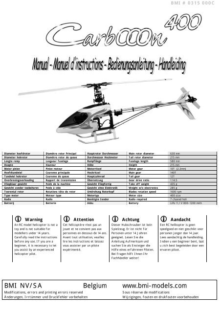
<strong>BMI</strong> # 0315 000C<br />
Diameter hoofdrotor Diamètre rotor Principal Hauptrotor Durchmesser Main rotor diameter 630 mm<br />
Diameter hekrotor Diamètre rotor de queue Durchmesser Heckmotor Tail rotor diameter 215 mm<br />
Lengte romp Longueur fuselage Rumpflänge Fuselage length 580 mm<br />
Hoogte Hauteur Höhe Heigth 215 mm<br />
Motor pinion Pinion moteur Motorritzel Motor gear 10T (2.3mm)<br />
Hoofdtandwiel Couronne principale Heckritzel Main gear 140T<br />
Tandwiel hekrotor Couronne de queue Hauptzahnrad Tail gear 12T<br />
Overbreningsverhouding Rapport de transmission Übersetzung Gear drive ratio 1:14:5<br />
Vliegklaar gewicht Poids de la machine Gewicht Fliegfertig Take off weight 435 g<br />
Gewicht zonder toebehoren Poids à vide Gewicht ohne Elektronik Weight w/o electronics 285 g<br />
Toerental rotor Rotations tête de rotor Umdrehung Rotorkopf Blades rotation speed 1600 rpm<br />
Type motor Moteur type Motortyp Motor size 400 size<br />
Radio Radio Benötigte Sender Radio required 7 channel heli<br />
Batterij Batterie Akku Battery LiPo 11,1 V 800~1200 mAh<br />
Warning<br />
An RC model helicopter is not a<br />
toy and is not suitable for<br />
modellers under 14 years.<br />
Carefully read the instructions<br />
before any use. If you are a<br />
beginner, it is necessary to let<br />
you assist by an experienced<br />
helicopter pilot.<br />
<strong>Attention</strong><br />
Cet hélicoptère n’est pas un<br />
jouet et ne convient pas aux<br />
personnes en dessous de 14 ans.<br />
Avant tout utilisation, veuillez<br />
lire les instructions et laissez<br />
vous assister par un pilote<br />
expérimenté.<br />
Achtung<br />
Dieser Hubschrauber ist kein<br />
Spielzeug. Er ist nicht für<br />
Personen unter 14 Jahren<br />
geeignet. Lesen Sie die<br />
Anleitung Aufmerksam und<br />
suchen Sie als Ensteiger die<br />
Hilfe eines erfahrenen Piloten.<br />
Bei Fragen hilft Ihnen Ihr<br />
Fachhändler weiter!<br />
Aandacht<br />
Een RC helikopter is geen<br />
speelgoed en niet geschikt voor<br />
personen jonger dan 14 jaar.<br />
Lees aandachtig de handleiding.<br />
Indien u een beginner bent, laat<br />
u zich best begeleiden door een<br />
ervaren piloot.<br />
<strong>BMI</strong> NV/SA Belgium www.bmi-<strong>models</strong>.com<br />
Modifications, errors and printing errors reserved<br />
Sous réserve de modifications<br />
Änderungen, Irrtümmer und Druckfehler vorbehalten<br />
Wijzigingen, fouten en drukfouten voorbehouden
Read carefully and fully understand<br />
the instructions before commencing<br />
assembly. It is not recommended for a<br />
child to assemble the model.<br />
When assembling this kit, tools<br />
inclucing cutters are used. Extra care<br />
should be taken to avoid personal<br />
injury.<br />
Read and follow the instructions of all<br />
the parts that are needed, but not<br />
included in this kit (electronics, …).<br />
Keep out of reach of small childeren<br />
as suffocation may occur.<br />
Avoid flying in crowded areas and near<br />
small children.<br />
Make sure no one else is using the<br />
same frequency in your area.<br />
Avoid flying in heavy wind or while it<br />
rains.<br />
R/C Operating instructions<br />
Check all transmitter controls and<br />
trims are in neutral. Switch on the<br />
transmitter.<br />
Switch on the receiver.<br />
Inspect the servo throw and motor<br />
operation before taking-off.<br />
Reverse sequence when shutting down<br />
after flying.<br />
Make sure to disconnect and remove<br />
the batteries after flying.<br />
Check the model after flying and<br />
verify all screws are still fastened.<br />
<br />
<br />
<br />
<br />
<br />
<br />
<br />
Lisez attentivement les instructions<br />
avant de commencer l’assemblage. La<br />
construction du modèle par un enfant<br />
n’est pas recommandé.<br />
L’assemblage de ce kit requiert de<br />
l’outillage (couteau de modélisme).<br />
Manier ces outils avec précaution.<br />
Suivez les instructions d’utilisation des<br />
composants électroniques requis<br />
(options).<br />
Gardez hors de portée des enfants de<br />
bas age.<br />
Evitez de faire évoluer votre modèle à<br />
près de jeunes enfants ou à proximité<br />
de spectateurs.<br />
Assurez-vous que personne d’autre<br />
n’utilise la même fréquence sur le<br />
même terrain que vous. Ceci peut être<br />
source de sérieux accidents.<br />
Ne faites jamais évoluer votre modèle<br />
par vent fort ou sous la pluie.<br />
Procedure de mise en marche<br />
Assurez-vous que les trims soient au<br />
neutre. Allumez l’émetteur.<br />
Allumez le récepteur.<br />
Vérifiez la bonne marche de votre<br />
radiocommande avant de voler.<br />
Faites les opérations inverses après<br />
utilisation.<br />
Débranchez et éloignez les batteries<br />
du modèle.<br />
Contrôlez que toutes les vis soient bien<br />
serrées.<br />
<br />
<br />
<br />
<br />
<br />
<br />
Bevor Sie mit dem Zusammenbau<br />
beginnen, sollten Sie alle Anweisungen<br />
gelesen und verstanden haben. Es ist<br />
nicht empfohlen der Zusemmanbau<br />
durch ein Kind zu machen.<br />
Beim Zusammenbau dieses Bausatzes<br />
werden Messer und andere Werkzeuge<br />
verwendet. Zur Vermeidung von<br />
Verletzungen ist besondere Vorsicht<br />
angebracht.<br />
Wenn Sie elektronische Bauteile (nicht<br />
im Kit enthalten) benutzen, lesen Sie<br />
aufmerksam die Anleitung.<br />
Vermeiden Sie das Fliegen an<br />
überfüllten Plätzen und in der Nähe<br />
von kleinen Kindern.<br />
Prüfen Sie dass niemand in der<br />
Umgebung dieselbe Frequenz benutzt,<br />
denn dadurch können Unfälle<br />
entstehen.<br />
Vermeiden Sie das Fliegen bei starken<br />
Wind oder während Regen.<br />
Kontrollen vor der Flug<br />
Stellen Sie sich sicher dass alle<br />
Trimmhebel gut positioniert sind, und<br />
Sender einschalten.<br />
Empfänger einschalten.<br />
Die Funktion vor Abflug mit dem<br />
Sender überprüfen.<br />
Nach der Betrieb in umgekehrter<br />
Reihenfolge vorgehen.<br />
Die Batterie herausnehmen und<br />
abklemmen.<br />
Überprüfen ob alle Schrauben noch<br />
fixiert sind.<br />
<br />
<br />
<br />
<br />
<br />
<br />
Lees aandachtig en assimileer de<br />
handleiding vooraleer de kit te bouwen.<br />
Het is niet aangeraden de bouw door<br />
een kind uit te laten voeren.<br />
De bouw van deze kit vereist het<br />
gebruik van gereedschap (bvb messen).<br />
Wees heel voorzichtig bij het gebruik<br />
ervan.<br />
Lees ook aandachtig de handleiding van<br />
de componenten die niet in de kit<br />
inbegrepen zijn (electronica).<br />
Vermijd het vliegen in sterke wind of<br />
tijdens regen.<br />
Controleer voor het aanschakelen van<br />
uw zender dat GEEN zelfde frequentie<br />
reeds in gebruik is. Dit kan leiden tot<br />
ongevallen.<br />
Vermijd het vliegen in de buurt van<br />
toeschouwers en kleine kinderen.<br />
Voor de vlucht<br />
Let er op dat alle trims neutraal<br />
staan. Schakel de zender aan.<br />
Ontvanger aanschakelen.<br />
Test alle servo’s en motorfuncties<br />
vooraleer u vliegt.<br />
Na het gebruik eerst ontvanger<br />
uitschakelen en dan de zender.<br />
Batterij uit het model verwijderen en<br />
loskoppelen.<br />
Na het gebruik alle schroeven en<br />
moeren controleren.<br />
UK<br />
We guarantee this product to be free of<br />
defects in materials and workmanship at<br />
the moment of purchase. This guarantee<br />
doesn’t cover any component or piece<br />
demolished into use, modifications or<br />
deteriorations following from the application<br />
of adhesives or other products not<br />
mentioned in the instructions. In no case<br />
our compensation will exceed the<br />
purchase value of the product. We<br />
reserve the right to change or modify<br />
this guarantee without previous notice.<br />
As we have no control on the final<br />
assembly, no responsibility will be<br />
assured or assumed for any damage<br />
resulting from the bad use of the<br />
product. By using this product the user<br />
assumes the total responsibility.<br />
FR<br />
Ce produit est garanti contre tout vice<br />
de construction d’usine au moment de<br />
l’achat. Cette garantie ne couvre pas les<br />
composants détruits lors de l’usage du<br />
produit ou les modifications de<br />
l’ensemble ainsi que de la détérioration<br />
due à l’utilisation de colles ou autres<br />
produits non spécifiés dans la notice.<br />
Nous nous réservons le droit de changer<br />
ou modifier les clauses de cette garantie<br />
sans préavis.<br />
<strong>BMI</strong> s.a. décline toute responsabilité<br />
quant au dommages pouvant résulter de<br />
l’utilisation de ce produit, n’étant pas à<br />
même de contrôler nous-mêmes le<br />
montage et son utilisation correcte.<br />
DE<br />
<strong>BMI</strong> garantiert, dass dieser Produkt<br />
beim Kauf frei von Fabrikations- und<br />
Materialfehlern ist. Schäden durch<br />
falschen Gebrauch oder Montagefehler<br />
werden durch diese Garantie nicht<br />
gedeckt. Sobald das Produkt in Betrieb<br />
genommen wird, übernimmt der Benutzer<br />
aller daraus erwachsende<br />
Verantwortlichkeit. Reklamationen<br />
aufgrund von unsachgemäßer Behandlung<br />
oder Schadensersatzforderungen<br />
aufgrund missbräuchlicher Anwendung<br />
dieses Produkts müssen zurückgewiesen<br />
werden, da der praktische Betrieb<br />
außerhalb unseres Einflussbereiches<br />
liegt.<br />
NL<br />
Gefeliciteerd met uw aankoop. Dit<br />
produkt werd ontwikkeld door<br />
modelbouwers en gebouwd door onze<br />
ingenieurs met het doel een product met<br />
uitzonderlijke eigenschappen te<br />
verwezenlijken. Het is belangrijk dat u<br />
de tijd neemt om aandachtig deze<br />
montagehandleiding tot het einde te<br />
lezen. Dit is een hoog technisch product,<br />
waarin de nieuwste technologische<br />
ontwikkelingen toegepast werden.<br />
<strong>BMI</strong> nv wijst elke verantwoordelijkheid<br />
af van schade als gevolg van het gebruik<br />
van dit produkt, daar wij niet de juiste<br />
inbouw, gebruik en veiligheidsvoorchriften<br />
kunnen controleren<br />
To assemble this model some tools are<br />
needed:<br />
Sharp hobby knife<br />
Needle nose pliers<br />
Phlips screwdriver (large and<br />
small)<br />
Triangle<br />
Scissors<br />
Wire cutter<br />
Thread Lock<br />
Following items are needed for<br />
operation:<br />
Servo: <strong>BMI</strong> # 801780 x 4<br />
or <strong>BMI</strong> # 801847 x 4<br />
LiPo Battery: 11,1V 800-1200mAh<br />
Gyro: <strong>BMI</strong> # 81176<br />
Brushless motor # 85550<br />
Brushless controller # 85511<br />
Afin d’assembler ce modèle, veuillez<br />
utiliser les outils suivant:<br />
<br />
<br />
<br />
<br />
<br />
<br />
<br />
Couteau de modélisme<br />
Pince à becs<br />
Tounevis Philips (grand et petit)<br />
Equerre à dessin<br />
Ciseaux<br />
Pinces coupantes<br />
Frein à filet<br />
Les articles suivants sont necessaries<br />
pour l’utilisation:<br />
Servo: <strong>BMI</strong> # 801780 x 4<br />
ou <strong>BMI</strong> # 801847 x 4<br />
Batterie LiPo: 11,1V 800-1200mAh<br />
Gyro: <strong>BMI</strong> # 81176<br />
Moteur Brushless # 85550<br />
Controleur Brushless # 85511<br />
Folgende Werkzeuge sind erforderlich<br />
zum Bauen dieses Modell<br />
Modellbaumesser<br />
Flachzange<br />
Schraubendreher (gross und<br />
klein)<br />
Winkelstreben<br />
Schere<br />
Seitenschneider<br />
Schraubensicher<br />
Folgende Teile sind erforderlich für<br />
der Gebrauch:<br />
Servo: <strong>BMI</strong> # 801780 x 4<br />
oder <strong>BMI</strong> # 801847 x 4<br />
LiPo Batterie: 11,1V 800-1200mAh<br />
Kreisel: <strong>BMI</strong> # 81176<br />
Brushless Motor # 85550 und<br />
Brushless Drehzahlsteller # 85511<br />
Voor het bouwen van dit model dient u<br />
volgend gereedschap te gebruiken:<br />
Modelbouwmes<br />
Bektang<br />
Kruisschroevendraaier (groot en<br />
klein)<br />
Geodriehoek<br />
Schaar<br />
Kniptang<br />
Borgmiddel<br />
Volgende onderdelen zijn noodzakelijk<br />
voor het gebruik van uw toestel:<br />
Servo: <strong>BMI</strong> # 801780 x 4<br />
of <strong>BMI</strong> # 801847 x 4<br />
LiPo Batterij: 11,1V 800-1200mAh<br />
Gyro: <strong>BMI</strong> # 81176<br />
Brushless motor # 85550<br />
Brushless regelaar # 85511<br />
2
Step 1<br />
Use the parts from Bag B and follow the<br />
following instructions.<br />
1. Clean the main axle.<br />
2. Apply a light oil on the one-way bearing<br />
(047) before sliding the one-way (046) over<br />
the axle.<br />
3. Mount the spur gear (045) on the mainaxle.<br />
Fasten it with the M2 and apply threadlock<br />
on the M2 nut.<br />
<strong>Attention</strong>: Please check that the main axle<br />
and the one-way (047) are level.<br />
Etape 1<br />
Utilisez les pièces du sachet B et suivez les<br />
instructions suivantes.<br />
1. Nettoyez l’axe principale.<br />
2. Appliquez de l’huile fine sur le<br />
roulement de la roue libre (047) avant de<br />
glisser la roue libre (046) sur l’axe.<br />
3. Montez la couronne principale (045)<br />
sur l’axe principale. Montez le vis M2 et<br />
appliquez du frein à filet sur l’écrou.<br />
ATTENTION: Vérifiez que l’axe principale<br />
et la roue libre soient à la même hauteur.<br />
Stap 1<br />
Teile aus Beutel B benutzen und folgende<br />
Schritte folgen.<br />
1. Hauptwelle saubermachen.<br />
2. Leichtes Öl auf der Freilaufwelle (047)<br />
anbrengen. Freilauf (046) über die Welle<br />
schieben.<br />
3. Hauptzahnrad (045) auf die Hauptwelle<br />
montieren. Befestigen mit M2 Schraube<br />
und Schraubensicher auf die Mutter<br />
anbringen.<br />
ACHTUNG: Hauptwelle und Freilauflager sollen<br />
auf die gleiche Höhe montiert werden.<br />
Stap 1<br />
Gebruik de onderdelen uit zakje B en volg de<br />
volgende stappen.<br />
1. Reinig de hoofdas.<br />
2. Breng een lichte olie aan op de vrijloopas<br />
(047) vooraleer de vrijloop (046) over de as te<br />
schuiven.<br />
3. Monteer het hoofdtandwiel (045) op de<br />
hoofdas met de M2 schroef en breng<br />
borgmiddel aan op de M2 moer.<br />
OPGELET: zorg ervoor dat de hoofdas<br />
onderaan gelijk zit met de vrijloopas (047).<br />
3
Step 2<br />
1. Open Bag A an mount the assembled main<br />
gear set from step 1 in the upper part of the<br />
chassis. Mount the collar (057) with the<br />
slanted side towards the chassis.<br />
2. Mount the lower chassis on the upper<br />
chassis with the little screws.<br />
3. Mount the landing gear (Part F).<br />
4. Mount the assembled landing gear (F) on<br />
the lower part of the chassis. Don’t fully<br />
fasten the long rear screws because the<br />
lateral reinforcements still need to be applied.<br />
5. Install the motor and the corresponding<br />
motor pinion and screws. (eventual option)<br />
Etape 2<br />
1. Ouvrez le sachet A et montez la couronne<br />
centrale que vous venez de monter (étape 1) dans<br />
cette partie supérieure du châssis. Montez le<br />
collier (057) avec la partie incliné vers le chassis.<br />
2. Montez le châssis inférieur sur le châssis<br />
supérieur avec les petites vis.<br />
3. Assemblez le train d’atterrisage (sachet F).<br />
4. Montez le train d’atterrisage (F) sur la<br />
partie inférieur du châssis. Ne fixez pas encore<br />
les longues vis arrières, afin d’assembler plus<br />
facilement les renforts transversales<br />
5. Installez le moteur avec le pinion moteur et<br />
vis adéquat. (éventuellement en option)<br />
Schritt 2<br />
1. Beutel A offnen und die Hauptwelle<br />
(Schritt 1) einbauen. (057) mit der schräge<br />
Seite zur Rahmen einbauen.<br />
2. Unterer Rahmen auf oberer Rahmen<br />
montieren mit der kleine Schrauben.<br />
3. Landegestell bauen (Beutel F).<br />
4. Landegestell (F) auf der untere<br />
Rahmen montieren. Hintere lange<br />
schrauben noch nicht festziehen weil die<br />
Verstärkungen noch angebracht werden<br />
mussen.<br />
5. Motor mit passender Ritzel und<br />
Schrauben installieren.<br />
Stap 2<br />
1. Open zakje A en monteer de hoofdas<br />
(stap 1) in het bovenste deel van het chassis.<br />
Monteer bovenaan de borgring (057) met de<br />
schuine kant naar het chassis toe.<br />
2. Onderste chassis op bovenste chassis<br />
monteren met kleine schroeven.<br />
3. Landingsgestel monteren (zakje F).<br />
4. Monteer het landingsgestel (F) op de<br />
onderste helft van het chassis. Draai de<br />
achterste lange schroeven nog niet volledig<br />
aan omdat de zijdelingse verstevigingen nog<br />
aangebracht dienen te worden.<br />
5. Installeer de motor met het bijpassende<br />
tandwiel en schroeven. (eventuele optie)<br />
4
Step 3 - 4<br />
1. Mount the tailrotor (L) as pictured on<br />
the tail boom (E). Install the complete tail on<br />
the tail boom. Please note the correct<br />
placement of the tail booms. The little holes<br />
on the tail boom indicate the correct distance<br />
for the assembly of the tail parts.<br />
2. Mount tail boom (072) onto the chassis.<br />
Pay attention that the tail boom is<br />
perpendiculary mounted. Fixen the (020, 054<br />
& 055).<br />
3. Mount the tail fin (085) and stabilizer<br />
(079) from bag J and attach the two lateral<br />
fixations (081) with the slanted side.<br />
4. Mount the tail rotorblades with the<br />
proper screws.<br />
5. Mount the gyroservo as shown.<br />
6. Mount the servorod (083). Determine<br />
the distance and then fasten the screws.<br />
Etape 3 - 4<br />
1. Montez le rotor anticouple (L) comme<br />
indiqué, sur la poutre de queue (E). Installez la<br />
partie arrière sur la poutre de queue. Faites<br />
attention au bon emplacement de la poutre de<br />
queue. Les petits trous indiquent la distance<br />
pour l’assemblage de la partie arrière.<br />
2. Montez la poutre de queue (072) sur le<br />
châssis. Veillez à ce qu’ elle soit installée<br />
verticalement. Fixez ensuite les vis (020, 054<br />
& 055).<br />
3. Montez le stabilisateur vertical (085)<br />
et le stabilisateur horizontal (079) du sachet<br />
“J” et fixez ensuite les deux renforcements<br />
latéreaux avec les parties découpées de biais<br />
(081) sur le châssis.<br />
4. Montez les pales d’anticouple avec les vis<br />
appropriées.<br />
5. Montez le servo de gyro comme indiqué.<br />
6. Montez la tringlerie (083). Vérifiez<br />
d’abord la distance avant de fixer les vis.<br />
Schritt 3 - 4<br />
1. Heckrotor (L) auf Heckrohr (E)<br />
montieren wie abgebildet. Kompletter Heckteil<br />
montieren auf das Heckrohr. Achten Sie<br />
darauf das die hinterne Locher im Heckrohr<br />
richtig angebracht sind um.<br />
2. Heckrohr (072) vertical auf der Rahmen<br />
montieren. Befesigen mit beigelieferte<br />
Schrauben (020, 054 & 055).<br />
3. Vertikale (085) und horizontale (079)<br />
Stabilisatoren aus Beutel J nehmen und<br />
zunächst die beide Verstärkungsstreben (081)<br />
auf der Rahmen montieren.<br />
4. Heckrotorblätter montieren.<br />
5. Gyroservo wie montieren wie abgebildet.<br />
6. Servostang (083) montieren. Distanz zur<br />
Servo kontrollieren und demnächst<br />
festschrauben.<br />
Stap 3 - 4<br />
1. Monteer de staartrotor (L) zoals<br />
afgebeeld op staartstuk (E). Plaats het<br />
volledige staartstuk op de staartbuis. Let er<br />
op dat je de gaatjes in de staartbuis<br />
achteraan correct plaatst, om zo de juiste<br />
afstand tussen de onderdelen te behouden.<br />
2. Monteer staartbuis (072) volledig op het<br />
chassis. Zorg ervoor dat het staartstuk (E)<br />
loodrecht gemonteerd wordt en draai de<br />
schroeven (020, 054 & 055) aan.<br />
3. Monteer de staartvin (085) en de<br />
stabilo (079) uit zakje J en breng de twee<br />
laterale stangen (081 zakje G) met de schuine<br />
kant (080) op het chassis aan.<br />
4. Monteer de staartbladen met aangepaste<br />
schroeven.<br />
5. Monteer de gyroservo zoals afgebeeld.<br />
6. Monteer de servostuurstang (083).<br />
Bepaal eerst de servoafstand en draai de<br />
schroeven dan pas aan.<br />
5
Step 5<br />
1. Mount the stabilizer bar on the rotor<br />
head (bag I).<br />
2. Mount both paddles (005) and mount<br />
collar (004) on the stabilizer bar with the<br />
adequate screw<br />
3. Mount the Hiller paddles (001). Take<br />
care that the left-right distance is equal<br />
(picture). Fasten all the screws and make<br />
sure that the stabiliser bar is horizontal.<br />
<strong>Attention</strong>: Mount the Hillerpaddles so that<br />
they turn RIGHT.<br />
Etape 5<br />
1. Montez la barre stabilisatrice sur la<br />
tête du rotor (sachet I).<br />
2. Montez les pièces 005 et 004 sur la<br />
barre stabilisatrice avec les vis adéquates.<br />
3. Montez les palettes de Bell (001)<br />
Assurez vous que la distance gauche-droite de<br />
l’axe Hiller est égale (cfr image). Fixer toutes<br />
les vis et assurez-vous que la barre de Bell<br />
soit bien horizontale.<br />
<strong>Attention</strong>: Montez les palettes de Bell de<br />
façon qu’elles tournent vers la DROITE.<br />
Schritt 5<br />
1. Stabilisator auf der Hauptrotor montieren<br />
(Beutel I).<br />
2. 005 und 004 auf die Hiller Welle montieren<br />
mit der richtige Schrauben.<br />
3. Hillerpaddels (001) montieren. Bitte darauf<br />
achten dass der Abstand (links-rechts) egal ist<br />
wie auf das Bild. Schrauben anziehen und<br />
kontrollieren ob die Hiller Welle horizontal liegt.<br />
ACHTUNG: Hillerpaddels so montieren dass sie<br />
nach Rechts drehen.<br />
Stap 5<br />
1. Monteer de stabilisatorstang op de<br />
rotorkop (zakje I).<br />
2. Monteer linker en rechterpaddel (005)<br />
en schuif stelring (004) met bijpassend<br />
schroefje op de stabilisatiestang.<br />
3. Monteer nu de Hillerpaddles (001). Let<br />
er op dat bij het monteren van de Hilleras de<br />
afstand links-rechts evenredig is (zie<br />
tekening), schroef vervolgens alles vast, en<br />
let erop dat de stabilisatorbar horizontaal<br />
staat.<br />
Opgelet, de Hillerpaddles RECHTSDRAAIEND<br />
monteren.<br />
8
Step 6<br />
1. Mount the swashplate (H) on the main<br />
axle. Mount the rotorhead (I) and apply<br />
thread-lock to the M2 nut.<br />
2. Mount the links from bag K as pictured.<br />
3. Mount the three links (052) on the<br />
swashplate, in order to mount the 3<br />
remaining servos.<br />
<strong>Attention</strong>: when using the <strong>BMI</strong> servos 801847,<br />
you don’t need to make any adaptations.<br />
4. Mount the rotorblades (M) on the main<br />
rotor grip (I). Don’t overtighten the<br />
screws, and make sure the blades have<br />
sufficient lateral movement.<br />
Etape 6<br />
1. Montez le plateau cyclique (H) sur l’axe<br />
principale. Montez la tête de rotor (I) et<br />
appliquez du frein filet sur l’écrou M2.<br />
2. Montez la tringlerie du sachet K comme<br />
indiqué.<br />
3. Connectez les trois tringleries (052)<br />
avec le plateau cyclique et montez les<br />
trois servos.<br />
<strong>Attention</strong>: lorsque vous utilisez les servos <strong>BMI</strong><br />
801847, aucune adaptation n’est nécessaire.<br />
4. Montez finalement les pales principales<br />
(M) sur les fixations des pales<br />
principales (I). Ne serrez pas les vis trop<br />
fort, et vérifiez que les pales aient assez<br />
de mouvement latérale.<br />
Schritt 6<br />
1. Swashplate (H) auf die Hauptwelle<br />
montieren. Rotorkopf (I) montieren und<br />
Schraubensicherung anbrengen auf die<br />
Mutter M2.<br />
2. Gestänge (Beutel K) anbrengen wie<br />
abgebildet.<br />
3. Gestänge 052 montieren und verbinden<br />
mit den Servos.<br />
Achtung: Wenn Sie die <strong>BMI</strong> Servos 801847<br />
benutzen können diese ohne anpassung<br />
einbauen.<br />
4. Rotorblätter (M) auf die<br />
Rotorblätterhalter (I) montieren.<br />
Schrauben nicht zu fest anziehen, und<br />
darauf achten dass die Rotorblätter<br />
genügend lateral bewegen können.<br />
Stap 6<br />
1. Monteer de swashplate (H) op de<br />
hoofdas. Monteer de rotorkop (I) met<br />
bijgeleverde schroef en borg de M2 moer.<br />
2. Monteer alle stangen (zakje K), zoals<br />
afgebeeld.<br />
3. De drie stangen (052) monteren op<br />
swashplate, zo kan men de laatste drie servo’s<br />
op hun plaats monteren.<br />
OPGELET; indien met de <strong>BMI</strong> servo’s (801847)<br />
gebruikt zijn er geen aanpassingen vereist.<br />
4. Tijdens het monteren van de rotorbladen<br />
(M) op de rotorbladhouders (I) dienen de<br />
schroeven niet te vast aangetrokken te<br />
worden. Zorg ervoor dat de rotorbladen<br />
voldoende zijdelingse beweging hebben.<br />
9
3200 Kv Brushless motor 25A Brushless controller for # 0315-350 Brushless motor and Controller Standard and heading lock piezo gyro<br />
3600 Kv Brushless motor 25A Brushless Heli controller for # 85550 Aluminium main blade grip set Aluminium swash plate set<br />
Aluminium rotor hub set Aluminium wash-out set Aluminium tail blade grip set Aluminium tail gear box set<br />
Carbon main blades<br />
9 – 10 & 11T pinions<br />
12