
Create successful ePaper yourself
Turn your PDF publications into a flip-book with our unique Google optimized e-Paper software.
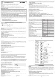
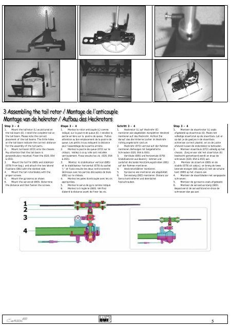
Step 3 - 4<br />
1. Mount the tailrotor (L) as pictured on<br />
the tail boom (E). Install the complete tail on<br />
the tail boom. Please note the correct<br />
placement of the tail booms. The little holes<br />
on the tail boom indicate the correct distance<br />
for the assembly of the tail parts.<br />
2. Mount tail boom (072) onto the chassis.<br />
Pay attention that the tail boom is<br />
perpendiculary mounted. Fixen the (020, 054<br />
& 055).<br />
3. Mount the tail fin (085) and stabilizer<br />
(079) from bag J and attach the two lateral<br />
fixations (081) with the slanted side.<br />
4. Mount the tail rotorblades with the<br />
proper screws.<br />
5. Mount the gyroservo as shown.<br />
6. Mount the servorod (083). Determine<br />
the distance and then fasten the screws.<br />
Etape 3 - 4<br />
1. Montez le rotor anticouple (L) comme<br />
indiqué, sur la poutre de queue (E). Installez la<br />
partie arrière sur la poutre de queue. Faites<br />
attention au bon emplacement de la poutre de<br />
queue. Les petits trous indiquent la distance<br />
pour l’assemblage de la partie arrière.<br />
2. Montez la poutre de queue (072) sur le<br />
châssis. Veillez à ce qu’ elle soit installée<br />
verticalement. Fixez ensuite les vis (020, 054<br />
& 055).<br />
3. Montez le stabilisateur vertical (085)<br />
et le stabilisateur horizontal (079) du sachet<br />
“J” et fixez ensuite les deux renforcements<br />
latéreaux avec les parties découpées de biais<br />
(081) sur le châssis.<br />
4. Montez les pales d’anticouple avec les vis<br />
appropriées.<br />
5. Montez le servo de gyro comme indiqué.<br />
6. Montez la tringlerie (083). Vérifiez<br />
d’abord la distance avant de fixer les vis.<br />
Schritt 3 - 4<br />
1. Heckrotor (L) auf Heckrohr (E)<br />
montieren wie abgebildet. Kompletter Heckteil<br />
montieren auf das Heckrohr. Achten Sie<br />
darauf das die hinterne Locher im Heckrohr<br />
richtig angebracht sind um.<br />
2. Heckrohr (072) vertical auf der Rahmen<br />
montieren. Befesigen mit beigelieferte<br />
Schrauben (020, 054 & 055).<br />
3. Vertikale (085) und horizontale (079)<br />
Stabilisatoren aus Beutel J nehmen und<br />
zunächst die beide Verstärkungsstreben (081)<br />
auf der Rahmen montieren.<br />
4. Heckrotorblätter montieren.<br />
5. Gyroservo wie montieren wie abgebildet.<br />
6. Servostang (083) montieren. Distanz zur<br />
Servo kontrollieren und demnächst<br />
festschrauben.<br />
Stap 3 - 4<br />
1. Monteer de staartrotor (L) zoals<br />
afgebeeld op staartstuk (E). Plaats het<br />
volledige staartstuk op de staartbuis. Let er<br />
op dat je de gaatjes in de staartbuis<br />
achteraan correct plaatst, om zo de juiste<br />
afstand tussen de onderdelen te behouden.<br />
2. Monteer staartbuis (072) volledig op het<br />
chassis. Zorg ervoor dat het staartstuk (E)<br />
loodrecht gemonteerd wordt en draai de<br />
schroeven (020, 054 & 055) aan.<br />
3. Monteer de staartvin (085) en de<br />
stabilo (079) uit zakje J en breng de twee<br />
laterale stangen (081 zakje G) met de schuine<br />
kant (080) op het chassis aan.<br />
4. Monteer de staartbladen met aangepaste<br />
schroeven.<br />
5. Monteer de gyroservo zoals afgebeeld.<br />
6. Monteer de servostuurstang (083).<br />
Bepaal eerst de servoafstand en draai de<br />
schroeven dan pas aan.<br />
5