993/964 Supercharger Kit - Installation Instructions - Vivid Racing
993/964 Supercharger Kit - Installation Instructions - Vivid Racing
993/964 Supercharger Kit - Installation Instructions - Vivid Racing

Create successful ePaper yourself
Turn your PDF publications into a flip-book with our unique Google optimized e-Paper software.
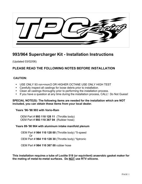
<strong>993</strong>/<strong>964</strong> <strong>Supercharger</strong> <strong>Kit</strong> - <strong>Installation</strong> <strong>Instructions</strong><br />
(Updated 03/02/06)<br />
PLEASE READ THE FOLLOWING NOTES BEFORE INSTALLATION<br />
CAUTION:<br />
• USE ONLY 93 ron+mon/2 OR HIGHER OCTANE USE ONLY HIGH TEST<br />
• Carefully inspect all castings for loose debris prior to installation.<br />
• Clean all castings thoroughly prior to performing the installation process.<br />
• If you have a question at any time during the installation process, CALL! Do Not Guess!<br />
SPECIAL NOTE(S): The following items are needed for the installation which are NOT<br />
included, you can obtain these items from your local dealer.<br />
Years ’96-’98 <strong>993</strong> with Vario-Ram<br />
OEM Part # <strong>993</strong> 110 128 11 (Throttle body)<br />
OEM Part # <strong>993</strong> 110 367 04 (Rubber hose)<br />
Years 89-’90 <strong>964</strong> with aluminum intake manifold plenum<br />
OEM Part # <strong>964</strong> 110 128 00 (Throttle body) *5-speed<br />
Or<br />
OEM Part # <strong>964</strong> 110 128 30 (Throttle body) *tiptronic<br />
OEM Part # <strong>964</strong> 110 367 00 rubber hose<br />
This installation requires a tube of Loctite 518 (or equivilent) anaerobic gasket maker for<br />
the mating of metal-to-metal surfaces. Do NOT use RTV silicone.<br />
PAGE 1
<strong>993</strong>/<strong>964</strong> <strong>Supercharger</strong> <strong>Kit</strong> Parts<br />
PAGE 2
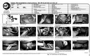
<strong>993</strong>/<strong>964</strong> <strong>Supercharger</strong> <strong>Kit</strong> Cast Parts List<br />
PAGE 3
INSTALLATION STEPS<br />
Step 1. Remove intake manifold. (The injector stacks are normally not removed but do inspect<br />
the injector stacks and rubber couplers for cracks. Replace if necessary). Locate left hold<br />
down bracket and install as shown in figure 1a. Use provided 6mm stud and attach to middle<br />
cooling shroud hold down. Follow the same installation procedure for the right hold down<br />
bracket, (see figure 1b). Make sure the bottom of the right hold down bracket seats flush on<br />
top of the power steering pump bracket. Depending on the model year, you may have to trim<br />
the bottom of the right hold down bracket so that it seats properly on top of the power steering<br />
pump bracket.<br />
Step 2. *<strong>993</strong> ONLY! Relocate smog pump to the right rear shock tower mount. Some<br />
modification to the pump discharge hose will be required. Cut the hose as needed.<br />
(Reference figure 2a) When relocating the pump, locate the inlet plumbing as pictured in<br />
figure 2b. (Please note, when removing the smog pump bracket from the engine reinstall the<br />
6.0mm. fastener to the oil pressure switch housing.)<br />
PAGE 4
Step 3. Install the intake manifold provided as shown in figure 3a. (Note: Loosen upper hose<br />
clamps on injector stacks before installing. Next, pull down evenly with the Right &Left hold<br />
down brackets installed, and then tighten the injector stacks.) For <strong>964</strong>, the fuel pressure<br />
regulator bracket must be removed prior to the installation of the intake manifold. This will allow<br />
the fuel pressure regulator to have some movement, allowing it to clear the manifold. The fuel<br />
pressure regulator can be secured with nylon ties. The hard fuel line near the AC compressor<br />
may be shifted slightly to clear the manifold.<br />
Step 4. Paint the fiberglass Bypass Air Duct and install it between the factory cooling shroud<br />
and Heat Exchanger connection.<br />
Step 5. Install the fan bracket to the fan housing using the supplied (3) 6.0 x 1.0mm. socket<br />
head bolts as shown in figure 5a. (Note: The fan bracket must properly rest on the factory fan<br />
housing as it also supports the nose of the supercharger. Trim the factory plastic cooling<br />
shroud so the entire footing of the fan bracket rest directly on the factory fan housing. Part of<br />
the fan bracket will over lap the fiberglass bypass air duct installed earlier, this will keep the<br />
duct in place.)<br />
PAGE 5
Step 6. Locate the provided throttle cable stop. Carefully remove the rubber grommet from the<br />
engine sheet metal and pull through to the underside of the vehicle. Install the Throttle Stop as<br />
shown in figure 6. (Note: The throttle stop should face upward.) and then pull the cable back<br />
through the sheet metal. In this step, you are using the provided throttle cable stop on the<br />
backside of the engine sheet metal to shorten the reach of the cable. If this step is not<br />
performed properly you will experience diminished performance since you will never run at full<br />
throttle! You must check for the throttle plate to make sure it opens fully once the installation is<br />
completed. This should also be checked periodically.<br />
PAGE 6
Step 7. Remove the alternator pulley and fan pulley, then install the provided fan pulley with<br />
the original nut and conical washer. (Note: Use Red Loctite!) Remove the belt tension sensor<br />
and bypass the circuit by connection the two wires.<br />
Step 8. Raise the vehicle and get ready to change the crank pulley. For <strong>993</strong>, remove the<br />
catalytic converters, mufflers, and the cross-over heat exchanger pipe. For <strong>964</strong>, only remove<br />
the center muffler. (Use care. Do not break off hardware. Use heat if necessary to loosen<br />
hardware.) Remove the engine support bracket (motor mount), this will allow the front of the<br />
engine to tilt down, so you can remove the crank pulley. Make sure the engine is supported so<br />
that all the weight is not resting on the transmission mounts. Remove the factory crank pulley<br />
and install the supplied crank pulley. For <strong>993</strong>, use the provided hub flange. Install the hub<br />
flange on the new crank pulley using 6 x 1.0mm “flange” bolts. (Note: Always reinstall the<br />
hub bolts and crank pulley bolt with Red Loctite!)<br />
PAGE 7
Step 9. With the engine support bracket (motor mount) on the bench, verify your bracket has<br />
an extra layer welded on from the factory (as shown in figure 9a). If your bracket does NOT<br />
have the extra layer, then add alignment shims to the spacer in the bottom hole of the tension<br />
plate. You want the bottom spacer to be about the same height as the top. (as shown in<br />
figure 9b and figure 9c). Next, center punch and drill holes through the mount using the<br />
supplied template (as shown in figure 9d). Install the tensioner plate and coil bracket (<strong>993</strong><br />
only) using the provided hardware and spacers as shown in figure 9e. (Note: The coil<br />
bracket is only used for <strong>993</strong> installations! <strong>964</strong> coil assemblies remain in the factory<br />
locations.) Install the coil assemblies as shown in figure 9f.<br />
PAGE 8
Step 10. Reinstall the engine support bracket and exhaust. Next step is to prepare the<br />
supercharger.<br />
Step 11. Build up supercharger assembly as shown in figure 11a. Note: The inlet manifold<br />
uses (2) 8.00x1.25 studs w/jap nuts (smaller head). Seal with Loctite 518, then attach<br />
compressor bypass valve to the outlet manifold using the 6.0x1.0 socket head bolts and seal<br />
with Loctite 518. Next, mount to the supercharger using (3) 8.0x1.0 socket head bolts and one<br />
stud. Note: Install the (3) supercharger hold down bolts ( (2) 10 x 100mm. & (1) 10x<br />
90mm).<br />
Step 12. Install the supercharger assembly as shown in figure 12a, bolting the supercharger<br />
to the fan bracket and the intake manifold. '96-up cars refer to figure 12b for routing of the AC<br />
lines prior to installing supercharger.<br />
PAGE 9
Step 13. Refer to figure 13a and install the discharge elbow and XS pressure relief valve.<br />
Make sure the vent port on top of the XS pressure relief valve is left open to the atmosphere.<br />
Locate the fuel pressure test port on the left side fuel rail (driver's side in USA). Remove the<br />
test port cap and remove the schrader valve from inside the port. Install the supplied fuel<br />
injector assembly onto the the test port using the 90 degree fitting. The fuel injector itself goes<br />
into the brass compression fitting on the discharge elbow. Make sure the injector is positively<br />
pushed into the brass fitting and locked in place. You should check it again later.<br />
Step 14. Install the air flow meter, idle motor, and air filter. Use the short aluminum tube<br />
provided to extend the air flow meter out. For <strong>993</strong>, the air filter clamps directly on the air flow<br />
meter. For <strong>964</strong>, use the adaptor provided. Hook up engine vacuum lines, refer to the supplied<br />
drawing (<strong>964</strong>/<strong>993</strong> Vac. Line) . If the vehicle you are working on gets a new throttle body &<br />
rubber hose, make sure the inlet air temp sensor goes into the new rubber hose. The<br />
next step is to install the Engine Management System, but before that, you can start the<br />
engine and let it idle to make sure there are no vacuum leaks. You can also check for proper<br />
belt alignment. You may have to a shim the tensioner to get proper belt alignment. Call us for<br />
assistance.<br />
Step 15. Install Engine Management System (EMS) as per supplied drawing (<strong>964</strong>/<strong>993</strong> EMS<br />
Diag.) . We recommend soldering all connections. NOTE: Make sure the DME box has a<br />
factory (stock) chip in it otherwise you may damage the engine. Do not get 12-volt<br />
source from ignition coil ! Do not remove any magnetic shielding from the crank senor<br />
harness !<br />
PAGE 10
Step 16. Testing procedure for the Engine Management System. Test the injector function by<br />
putting a noid (test) light on the injector connector. This light should illuminate under positive<br />
manifold pressure only. This indicates the proper function of the injector under boost<br />
conditions. Make sure the injector connector is FIRMLY pushed on the injector all the<br />
way! You will have to wiggle and push hard.<br />
DO NOT ATTEMPT TO TEST DRIVE CAR IF THIS PROCEDURE DOES NOT GO AS<br />
OUTLINED. Any problems call immediately @ 410-799-7223.<br />
PAGE 11
<strong>964</strong>/<strong>993</strong> Vac. Line<br />
PAGE 12
<strong>964</strong>/<strong>993</strong> EMS Diag<br />
WARNING: USE ONLY WITH STOCK DME!<br />
<strong>993</strong> – Mount EMS box in the engine compartment on the fuse panel lid located at the left rear<br />
corner.<br />
<strong>964</strong> – Mount EMS box in the engine compartment on the back firewall away from the ignition<br />
coils.<br />
Once the EMS box is mounted, located the BLACK 3-wire connector for the engine crank<br />
sensor. It is near the left strut tower. Confirm it is the crank sensor connector because the<br />
cylinder head temp sensor is located in the same general area. If you are not sure, follow the<br />
wire into the transmission bell housing.<br />
Refer to the drawing below. Carefully cut into the WHITE wire as close to the connector as<br />
possible to ensure an optimum crank signal. It is very important that you DO NOT remove any<br />
of the magnetic shielding from the harness.<br />
NOTE: Make sure the spark plug wires and ignition coils are in good condition and free of<br />
cracks. Worn out ignition components will create magnetic interference and will greatly<br />
decrease the performance. We recommend using factory spark plug wires and ignition coils.<br />
Some of the aftermarket parts are not as well shielded magnetically.<br />
PAGE 13