Installation Instructions - Vivid Racing
Installation Instructions - Vivid Racing
Installation Instructions - Vivid Racing

Create successful ePaper yourself
Turn your PDF publications into a flip-book with our unique Google optimized e-Paper software.
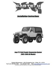
<strong>Installation</strong> <strong>Instructions</strong>6” Performance Suspension System1999-2003 GM 4WD K1500 P/U & SUVFabtech Motorsports 4331 Eucalyptus Ave. Chino, CA 91710Tech Line 909-597-7800 Fax 909-597-7185 Web www.fabtechmotorsports.com
www.fabtechmotorsports.com6” 1999-2003 GM 4WD K1500FTS21000 / FTS21001 / FTS21002 / FTS21003PARTS LISTFTS21000 99-00 Box 1 of 2 All MODELS FTS21001 1999 P/U only Box 2 of 21 FT10013D Spindle -Driverside 1 FT20021 Front Crossmember1 FT10013P Spindle - Passenger side 1 FT20022 Rear Crossmember2 FT20206 CV Spacers 1 FT20048 Impact Strut Rear Mount 1999 only1 FT20034 Skid Plate 2 FT20049 Impact Strut 1999 only1 FT20027 Diff Drop bracket (Pass) 2 FTBK4 4" Blocks1 FT20028 Diff Drop bracket (Drv) 4 FT1500U-3 U Bolts2 FT20040 Sway Bar links 2 FT20024 Add a Leafs1 FT20036 Bushing Kit 2 CB-07X5 Center Pin Bolt1 FT20026 Hardware 2 NUT-HF-07 Center Pin Nuts1 FT20038 Hardware 2 FT20025 Rear Bump stop Spacers1 FT20039 Hardware Kit2 FT20144 Torsion Bar Bracket1 FT916H U Bolt HardwareFTS21002 2000-04 P/U Box 2 of 2 FTS21003 2000-04 SUV Box 2 of 21 FT20021 Front Crossmember 1 FT20021 Front Crossmember1 FT20022 Rear Crossmember 1 FT20022 Rear Crossmember2 FT20054 Impact Strut Mount 2 FT20054 Impact Strut Rear Mount2 FT20023 Impact Strut 2 FT20023 Impact Strut2 FTBK4 4" Blocks 1 FT20055 Hardware Kit4 FT1500U-3 U Bolts 2 FT20052 Torsion Bar Mount1 FT916H U Bolt Hardware2 FT20024 Add a Leafs2 CB-07X5 Center Pin Bolt2 NUT-HF-07 Center Pin Nuts2 FT20025 Rear Bump stop Spacers1 FT20039 Hardware Kit2 FT20144 Torsion Bar BracketNOTE- SUV Models Require FTS1599-2 Rear Kit to complete installationDO NOT ALTER THE FINISH OF THESE COMPONENTS, EXAMPLE- CHROMING, ZINC PLATING ORPAINTING. CHANGING THE FINISH CAN CAUSE STRUCTURAL FATIGUEOF COMPONENTS.SUSPENSION SYSTEM MUST BE INSTALLED WITH FABTECH SHOCK ASBORBERS
HARDWARE LIST:FT20026FT20038Qua DescriptionQua Description2 5/8-11x 5-1/2" Hex Cap Bolt 4 1/2-13 X 3 Button Head2 5/8-11x 4-1/2" Hex Cap Bolt 12 10mm x 1.5 x 70mm4 5/8-11 Steel Lock Nut 12 10mm Flat Washer8 5/8" SAE Flat Washer 1 Thread lock Compound2 3/8"-16 Nyloc Lock Nut 1 1/2-13 x 1-1/4" Hex Cap Bolt1 9/16-12 x 5" Hex Cap Bolt 1 1/2-13 Steel Lock Nut1 9/16-12 x 4" 2 1/2" SAE Flat Washer2 9/16-12 x 1-3/4" 6 7" Tyraps4 10mm x 1.5 x 60mm8 9/16" SAE Flat Washer4 10mm Flat Washer4 9/16-12 Steel Lock Nut2 1/4-20 x 3/4" Hex Cap Bolt FT200392 1/4" SAE Flat Washer Qua Description2 1/4" Split Lock Washer 4 7/16-14 x 3-1/2" Hex Cap BoltFT20055 2 1/2-13 x 1-1/4" Hex Cap BoltQua Description 4 7/16-14 x 1-1/4" Hex Cap Bolt4 7/16-14 x 3-1/2" Hex Cap Bolt 8 7/16-14 Nyloc Lock Nut2 1/2-13 x 1-1/4" Hex Cap Bolt 2 1/2-13 Steel Lock Nut4 7/16-14 x 1-1/4" Hex Cap Bolt 16 7/16" SAE Flat Washer8 7/16-14 Nyloc Lock Nut 4 1/2" SAE Flat Washer2 1/2-13 Steel Lock Nut 8 7/16-14 x 1-1/4" Hex Cap Bolt16 7/16" SAE Flat Washer 8 7/16-14 Steel Lock Nut4 1/2" SAE Flat Washer 16 7/16" SAE Flat Washer2 9/16-12 x 3" Hex Cap Bolt 2 10mm-1.5 x 25mm2 9/16-12 Steel Lock Nut 2 10MM Split Lock Washer4 9/16" SAE Flat WasherTOOL LIST: (NOT INCLUDED)• FLOOR JACK & JACK STANDS• ASSORTED METRIC AND S.A.E SOCKETS, & WRENCHES• LARGE C CLAMP OR C CLAMP VISE GRIPS• DIE GRINDER WITH CUTOFF WHEEL OR SAWZALL• TORSION BAR REMOVAL TOOL• TORQUE WRENCH•VEHICLES THAT WILL RECEIVE OVERSIZED TIRES SHOULD CHECK BALL JOINTS, TIE RODS ENDS AND IDLER ARMEVERY 2500-5000 MILES FOR WEAR AND REPLACE AS NEEDEDCHECK ALL PARTS INCLUDED IN THIS KIT TO THE PARTS LIST ABOVE BEFORE BEGINNING INSTALLATION OF THEKIT. IF ANY PIECES ARE MISSING, CONTACT FABTECH AT 909-597-7800READ ALL INSTRUCTIONS THOROUGHLY FROM START TO FINISH BEFORE BEGINNING INSTALLATION! IF THESEINSTRUCTIONS ARE NOT PROPERLY FOLLOWED, SEVERE FRAME, DRIVELINE AND / OR SUSPENSION DAMAGE MAYRESULT.NOTE- PRIOR TO THE INSTALLATION OF THIS SUSPENSION SYSTEM A FRONT END ALIGNMENT MUST BEPERFORMED AND RECORDED. DO NOT INSTALL THIS SYSTEM IF THE VEHICLE ALIGNMENT IS NOT WITHINFACTORY SPECIFICATIONS. CHECK FOR FRAME AND SUSPENSION DAMAGE PRIOR TO INSTALLATION. THISSUSPENSION SYSTEM DOES NOT REQUIRE WELDING FOR INSTALLATION. DO NOT WELD ANY OF THESECOMPONENTS.
THE INSTALLATION OF THIS SUSPENSION SYSTEM SHOULD BE PERFORMED BY TWOPROFESSIONAL MECHANICS.FRONT SUSPENSION INSTRUCTIONS:1. With the vehicle on level ground set the emergency brake andblock the rear tires. Jack up the front end of the truck andsupport the frame rails with jack stands. NEVER WORKUNDER AN UNSUPPORTED VEHICLE! Remove the fronttires.2. Locate the torsion bar adjusting cams and threaded bolts.Measure exposed threads of torsion bar adjusting bolts andrecord for reinstallation. Mark torsion bars indicating driver andpassenger. Using a torsion bar removal tool unload the torsionbars and remove the crossmember and bars. Retain thehardware for reinstallation. NOTE- Do not attempt to unload orremove torsion bars without the proper torsion bar tool. TorsionBars are under extreme spring load.10. Remove the upper and lower ball joint nuts. Disconnect theupper and lower ball joints from the steering knuckle by strikingthe knuckle with a large hammer next to each ball joint on theknuckle to dislodge the ball joints. Use care not to hit the balljoints when removing. Retain nuts and discard knuckle. SEEPHOTO BELOW3. Remove the sway bar link ends from the sway bar and lowercontrol arm and discard.4. Remove the stock shocks and discard.5. Remove the stock lower rubber bump stops from the frameand discard.6. Disconnect the tie rod ends from the steering knuckle bystriking the knuckle to dislodge the tie rod end. Use care not todamage the tie rod end when removing. SEE PHOTO BELOW11. Remove the lower control arms from the frame and retainthe hardware for reinstallation.12. Remove front factory differential skid plate and splashshield and discard. Retain hardware for front crossmemberinstallation.13. Disconnect front driveshaft from differential housing andretain bolts and u joint clamps for reinstallation.14. Disconnect the electrical connection including the tworetaining clamps and the vacuum line from differential housing.15. Remove the differential rear crossmember and discard.Remove differential housing assembly from vehicle. Retainhardware for reinstallation.16. Locating the factory rear differential crossmember mount onthe driver side mark and cut the “L” mount flush from the sideof frame pocket with a Sawzall or Die Grinder. SEE PHOTOBELOW7. Unplug the ABS brake connection from the frame and controlarm. Remove the brake hose bracket from the steering knuckle.Remove the caliper from the rotor and place above the uppercontrol arm during this portion of the installation.8. Remove the wheel stud clips and discard. Remove brakerotor from the steering knuckle. Remove bearing cover, axlenut, washer, axle shaft and hub bearing and retain parts andhardware for reinstallation.9. Disconnect CV axles from differential housing and remove.
17. Locate the mounting bushing eye on the upper front side ofthe differential housing and mark the housing with a cut linesmooth to the housing. Using a sawzall cut the entire ear off thehousing. SEE BELOW PHOTODiff Housing Bracket21. Locate and install the Fabtech rear crossmember into thefactory lower control arm pockets using the stock hardware andtorque to 90lbs. Locate and install the Fabtech urethane bumpstops to the angled portion of the crossmember using the 3/8”nuts from Hardware Kit FT20026 and torque to 15lbs SEEBELOW PHOTO18. On the driver side of the differential housing, above the rearbushing mount mark and cut/grind with a die grinder thealuminum fins vertically upward to allow housing to sit intonew crossmember mount. SEE PHOTO BELOW22. Locate and install the Fabtech Passenger side Diff bracket tothe bottom of the factory mount with the wide end of thebracket to front of the vehicle using the stock hardware. Torqueto 70lbs. SEE BELOW PHOTOPhoto shown with aluminum fins cut19. Locate the C shaped Fabtech differential bracket and installbushings and sleeve in bracket from Bushing Kit FT20036.20. Place differential bracket to the differential housing andremove the appropriate 4 housing bolts. Bracket should bepositioned with the bushing eye to the top side of the housing.Using provided the 10mm x 1.5 x 60mm bolts and washers inhardware kit FT20026 attach the differential bracket to housingand torque to 30 lbs. using thread lock compound. Note- Someleakage of the differential oil is normal during this process.Recheck and fill diff housing oil once differential is mounted invehicle. SEE PHOTO NEXT COLUMN
23. Place the differential housing into the rear crossmemberusing 9/16”-12 x 4” bolt, nut and washers on the driver side and9/16”-12 x 1-3/4” bolts, nuts and washers on the passenger sidefrom hardware kit FT20026, leave loose. SEE PHOTO BELOW26. Torque the rear driver side diff bushing bolt to 70lbs andpassenger side diff bushing bolts to 70lbs.27. Install the lower control arms into the new crossmembersusing the 5/8” x 5-1/2” and 5/8” x 4-1/2” bolts nuts and washersfrom hardware kit FT20026. Torque to 125lbs.28. Using ½” x 1-1/4” Bolt, nut and washers attach the rear ofthe skid plate to the bottom of the rear crossmember and torqueto 70lbs.29. Torque the front crossmember frame pocket bolts to 125lbsand the bottom bolts to125lbs.24. Locate and install the Fabtech front crossmember into thefactory lower control arm pockets using the stock hardware,leave loose. Locate the access hole on the bottom of thecrossmember to thread the factory bolts into the factory skidplate bolt holes. Leave loose. SEE PHOTO BELOW30. Locate the steering knuckle FT10013D for the driver side.Attach the upper control arm to the new knuckle using thefactory hardware and torque to 35LBS. Attach the lowercontrol arm to the knuckle using the stock hardware and torqueto 70 lbs.31. Reinstall the hub bearing assembly using the stock hardwareand torque flange bolts to 125lbs. Reinstall brake rotor andcaliper. Torque caliper bolts to 30lbs.32. Re-route the brake hose to the steering knuckle using thefactory steel guide clamp to the back of the steering knuckle andattach with ¼” x 3/4” bolt and washer from Hardware kitFT20026. Torque to 10LBS. Check to make sure that the brakehose is routed as to allow full turning radius to the steeringwithout tire or suspension component contact. Route the ABSline to the front leg of the upper control arm next to the brakehose. Using provided plastic tyraps secure line and hose to theupper control arm away from the tire and wheel. SEE PHOTOBELOW25. Position the front differential urethane bushing mount intothe front crossmember tabs. Locate and install the differentialskid plate around the differential housing bushing using9/16”-12x5” bolt, nut and washers from hardware kit FT20026.Torque to 70lbs. SEE PHOTO BELOW33. Reinstall axle shaft through new knuckle and torque axle nutto 150 lbs. and install bearing cover.
34. Locate and install the Fabtech CV spacers between the CVaxle and the differential housing using 10mm x 70mm bolt andwasher from Hardware kit FT20038 with the provided threadlock compound and torque to 55 lbs. in a cross pattern.SEE PHOTO BELOW40. Locate and install the bushings and sleeves into the ImpactStrut bars. Attach the Impact Struts into the tabs on the backside of the lower control arm crossmember and rearward to theImpact Strut crossmember using 7/16” x 3-1/2” bolts, nuts andwashers from Hardware kit FT20038. Torque to 45lbs. NOTE-On 1999 models there will be two ½” bolts, nuts and washersleft over from this installation and can be discarded.Impact Strut Crossmember Mount instructions for2000-2003 Models-41. Locate and place the Impact Strut mounts to the bottom ofthe transmission crossmember aligning the three factory holes tothe mounts. Using 7/16” x 3-1/2” bolts and ½” x 1-1/4” bolts,nuts and washers from Hardware attach the mount to thecrossmember and torque the 7/16” bolts to and the ½” bolts to45lbs. SEE PHOTO BELOW35. Reattach the vacuum hose and electrical plug to the diff.36. Reattach the driveshaft to the differential yoke using thestock hardware and torque to 19lbs.37. Locate and install the Fabtech sway bar link ends with theprovided urethane bushings and washers using ½” x 3”Buttonhead bolts from Hardware kit 20038. Torque to 10lbs.SEE PHOTO BELOW42. Locate and install the bushings and sleeves into the ImpactStrut bars. Attach the Impact Struts into the tabs on the backside of the lower control arm crossmember and rearward to theImpact Strut mounts using 7/16” x 3-1/2” bolts, nuts andwashers from Hardware. Torque to 45lbs.38. Locate and install front shocks using the stock hardware andtorque the upper mount to 15lbs and lower to 55lbs.Resume installation for all models-43. Locate the torsion bar drop down mounts and installbushings and sleeves. Placing the Fabtech mount with thebushing eye directly below the factory torsion bar bushing eye,clamp to the mount to the bottom and side of the frame. Locatethe center of each hole, center punch the frame and drill outframe to 7/16” diameter. Attach torsion bar mounts using7/16” x 1-1/4” bolts, nuts and washers. Torque to 65lbs. Repeatsame procedure for the opposite side. SEE PHOTO BELOWImpact Strut Crossmember Mount instructions for 1999Models ONLY-39. Locate and install rear impact strut crossmember mount onthe outside of the frame rails, forward of the transmissioncrossmember. The outer flat portion of the new crossmembershould be positioned over the two factory frame holes on eachside of the frame with the bar sweeping rearward. Using 7/16” x1-1/4” bolts, nuts and washers from Hardware kit 20038 torqueto 45lbs .
44. Re install the driver and passenger side torsion bars with thefactory torsion bar crossmember installed into the new TorsionBar mounts using the factory hardware and torque to 70lbs.45. Set Torsion Bar adjusters to the recorded threadmeasurement from the disassembly.50. Locate and install the rear lift blocks with the provided shortcenter pin on the bottom of the block, to the axle. The short endof the block should face to the front of the vehicle. Using theprovided U bolts, nuts and washers align axle, lift blocks, andsprings and torque to U Bolts to 90lbs.. SEE PHOTO BELOW46. Install front tires and wheels. Torque lug nuts to wheelmanufacturers specifications.REAR P/U SUSPENSION INSTRUCTIONS:(See <strong>Instructions</strong> from FTS1599-2 for rear SUV’s)47. Jack up the rear end of the vehicle and support the framerails with jack stands. Supporting the rear differential removeand discard the rear shocks, u bolts and blocks. Lower axledown slowly. Use care not to over extend the brake hose.48. Clamp the leaf spring in the middle of the spring andremove the center bolt. SEE PHOTO BELOW51. Remove rear rubber bump stops and install extensionbracket using 10mm x 25mm bolt and lock washer, Torque to20lbs. Reinstall factory rubber bumps stop to the bottom of thenew bracket.52. Install new Fabtech shocks with the factory hardware andtorque upper bolts to 65lbs and lower bolts to 65lbs.53. Recheck all bolts for proper torque. Recheck brake hosesand lines for proper clearances.54. Check the fluid in the front differential and fill if need withfactory specification differential oil.49. Separate the springs and install the provided add a leaf withthe new center bolt in a pyramid pattern smallest on the bottomgraduating to the longest on top. The factory flat overload leafshould remain on the bottom of the pack. Clamp the spring andtighten the center bolt as not to leave a gap between the springs.Cut the thread of the bolt smooth with the nut. The nut shouldbe on the top of the leaf spring pack.55. Install tires and wheels and torque lug nuts to wheelmanufacturers specifications. Turn front tires left to right andcheck for appropriate tire clearance. Note- Some tires mayrequire trimming of the front plastic bumper valance.56. Check front end alignment and set to factory specifications.
RETORQUE ALL NUTS, BOLTS AND LUGS AFTER 50 MILES AND PERIODICALLY THEREAFTER.Product Warranty and Warnings-Fabtech provides a Limited Lifetime Warranty to the original retail purchaser who owns the vehicle, on which the product was originally installed, fordefects in workmanship and materials.The Limited Lifetime Warranty excludes the following Fabtech items; bushings, bump stops, ball joints, tie rod ends, limiting straps, cross shafts, heimjoints. These parts are subject to wear and are not considered defective when worn. They are warranted for 60 days from the date of purchase fordefects in workmanship.Coil over take apart shocks are considered a serviceable shock with a one year warranty on leakage only. Service seal kits are available separately forfuture maintenance. All other shocks are covered under our Limited Lifetime Warranty.Fabtech does not warrant any product for finish, alterations, modifications and/or installation contrary to Fabtech’s instructions. Alterations to the finishof the parts including but not limited to painting, powdercoating, plating and/or welding will void all warranties. Some finish damage may occur toparts during shipping which is considered normal and is not covered under warranty.Fabtech products are not designed nor intended to be installed on vehicles used in race applications or for racing purposes or for similar activities. (A“RACE” is defined as any contest between two or more vehicles, or any contest of one or more vehicle against the clock, whether or not such contest isfor a prize). This warranty does not include coverage for police or taxi vehicles, race vehicles, or vehicles used for government or commercial purposes.Also excluded from this warranty are sales outside of the United States of America.<strong>Installation</strong> of most suspension products will raise the center of gravity of the vehicle and will cause the vehicle to handle differently than stock. It mayincrease the vehicle’s susceptibility to a rollover, on road and off road, at all speeds. Extreme care should be taken to operate the vehicle safely at alltimes to prevent rollover or loss of control resulting in serious injury or death. Fabtech front end Desert Guards may impair the deployment or operationof vehicles equipped with supplemental restraining systems/air bag systems and should not be installed if the vehicle is equipped as so.Fabtech makes every effort to ensure suspension product compatibility with all vehicles listed in the catalog, but due to unknown auto manufacturersproduction changes and/or inconstancies by the auto manufacturer, Fabtech cannot be responsible for 100% compatibility, including the fitment of tireand wheel sizes listed. The Tire and Wheel sizes listed in Fabtech’s catalog are only a guideline for street driving with noted fender trimming. Fabtech isnot responsible for damages to the vehicle’s body or tires.Fabtech’s obligation under this warranty is limited to the repair or replacement, at Fabtech option, of the defective product only. All costs of removal,installation or re-installation, freight charges, incidental or consequential damages are expressly excluded from this warranty. Fabtech is not responsiblefor damages and/or warranty of other vehicle parts related or non related to the installed Fabtech product. This warranty is expressly in lieu of all otherwarranties expressed or implied. This warranty shall not apply to any product that has been subject to accident, negligence, alteration, abuse or misuseas determined by Fabtech.Fabtech suspension components must be installed as a complete system including shocks as shown in our current catalog. All warranties will becomevoid if Fabtech parts are combined and/or substituted with other aftermarket suspension products. Combination and/or substitution of other aftermarketsuspension parts may cause premature wear and/or product failure resulting in an accident causing injury or death. Fabtech does not warrant products notmanufactured by Fabtech.<strong>Installation</strong> of Fabtech product may void the vehicles factory warranty; it is the consumer’s responsibility to check with their local vehicle’s dealer forwarranty disposition before the installation of the product.It is the responsibility of the distributor and/or the retailer to review all warranties and warnings of Fabtech products with the consumer prior topurchase.Fabtech reserves the right to supercede, discontinue, change the design, finish, part number and, or application of parts when deemed necessary withoutwritten notice. Fabtech is not responsible for misprints or typographical errors within the catalog or price sheet.Instruction Sheet Part #- FT21000,1,2,3i04/20/04jj