Installation Instructions - Vivid Racing
Installation Instructions - Vivid Racing
Installation Instructions - Vivid Racing

You also want an ePaper? Increase the reach of your titles
YUMPU automatically turns print PDFs into web optimized ePapers that Google loves.
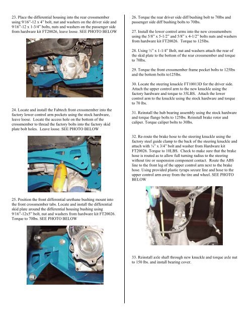
23. Place the differential housing into the rear crossmemberusing 9/16”-12 x 4” bolt, nut and washers on the driver side and9/16”-12 x 1-3/4” bolts, nuts and washers on the passenger sidefrom hardware kit FT20026, leave loose. SEE PHOTO BELOW26. Torque the rear driver side diff bushing bolt to 70lbs andpassenger side diff bushing bolts to 70lbs.27. Install the lower control arms into the new crossmembersusing the 5/8” x 5-1/2” and 5/8” x 4-1/2” bolts nuts and washersfrom hardware kit FT20026. Torque to 125lbs.28. Using ½” x 1-1/4” Bolt, nut and washers attach the rear ofthe skid plate to the bottom of the rear crossmember and torqueto 70lbs.29. Torque the front crossmember frame pocket bolts to 125lbsand the bottom bolts to125lbs.24. Locate and install the Fabtech front crossmember into thefactory lower control arm pockets using the stock hardware,leave loose. Locate the access hole on the bottom of thecrossmember to thread the factory bolts into the factory skidplate bolt holes. Leave loose. SEE PHOTO BELOW30. Locate the steering knuckle FT10013D for the driver side.Attach the upper control arm to the new knuckle using thefactory hardware and torque to 35LBS. Attach the lowercontrol arm to the knuckle using the stock hardware and torqueto 70 lbs.31. Reinstall the hub bearing assembly using the stock hardwareand torque flange bolts to 125lbs. Reinstall brake rotor andcaliper. Torque caliper bolts to 30lbs.32. Re-route the brake hose to the steering knuckle using thefactory steel guide clamp to the back of the steering knuckle andattach with ¼” x 3/4” bolt and washer from Hardware kitFT20026. Torque to 10LBS. Check to make sure that the brakehose is routed as to allow full turning radius to the steeringwithout tire or suspension component contact. Route the ABSline to the front leg of the upper control arm next to the brakehose. Using provided plastic tyraps secure line and hose to theupper control arm away from the tire and wheel. SEE PHOTOBELOW25. Position the front differential urethane bushing mount intothe front crossmember tabs. Locate and install the differentialskid plate around the differential housing bushing using9/16”-12x5” bolt, nut and washers from hardware kit FT20026.Torque to 70lbs. SEE PHOTO BELOW33. Reinstall axle shaft through new knuckle and torque axle nutto 150 lbs. and install bearing cover.