HCD-220 (3-V Blade) - Greenheck
HCD-220 (3-V Blade) - Greenheck
HCD-220 (3-V Blade) - Greenheck

Create successful ePaper yourself
Turn your PDF publications into a flip-book with our unique Google optimized e-Paper software.
Application and Design<br />
Ratings (See pages 2 and 3 for specific limitations)<br />
Pressure: Up to 15 in. wg (3.7 kPa) -<br />
differential pressure<br />
Velocity: Up to 4000 fpm (20.3 m/s)<br />
Temperature: -60°F to 600°F (-51°C to 315°C). Consult<br />
factory for other temperatures.<br />
H*<br />
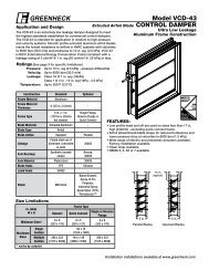
<strong>HCD</strong>-<strong>220</strong><br />
Industrial Control Damper<br />
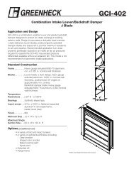
Model <strong>HCD</strong>-<strong>220</strong> is a heavy duty flanged industrial control damper. It is designed to control airflow and provide shut off in HVAC<br />
or industrial process control systems. <strong>HCD</strong>-<strong>220</strong> has a variety of optional features that allows this damper to be tailored to your<br />
application. This model is available with parallel or opposed blade action.<br />
Standard Construction<br />
Standard<br />
Optional<br />
Frame Depth (C) 8 in. (203mm) 10 in. (254mm)<br />
Frame Material Galvanized Steel 304SS, 316SS, Painted<br />
Frame Type<br />
Flanged Channel<br />
Frame Thickness 14 ga. (2mm) 10 ga. (3.5mm)<br />
12 ga. (2.7mm)<br />
Flange Width (D) 2 in. (51mm) 1 1/2 in. (38mm)<br />
2 1/2 in. (64mm)<br />
<strong>Blade</strong> Action Parallel Opposed<br />
<strong>Blade</strong> Material Galvanized Steel 304SS, 316SS, Painted<br />
<strong>Blade</strong> Seals None EPDM, Silicone<br />
<strong>Blade</strong> Thickness 12 ga. (2.7mm) 10 ga. (3.5mm)<br />
<strong>Blade</strong> Type<br />
3V<br />
Linkage Plated Steel 304SS, 316SS<br />
Jamb Seals None 301SS, 316SS<br />
Axle Diameter 3/4 in. (19mm) -<br />
Axle Bearing<br />
Stainless Steel<br />
Sleeve<br />
External Bronze Sleeve,<br />
External Relubricable<br />
Ball, Outboard Bronze,<br />
Outboard Relubricable<br />
Ball<br />
Axle Material Plated Steel 303SS, 316SS<br />
Axle Seals None O-ring, Double Gland<br />
Stuffing Box<br />
Paint Finishes None Epoxy,<br />
Hi Pro Polyester,<br />
Hi Temperature<br />
Aluminum,<br />
Hi Temperature Silver,<br />
Industrial Epoxy<br />
Permatector<br />
Size Limitations<br />
W x H<br />
Minimum<br />
Maximum Size<br />
Size Single Section Multi - Section<br />
Inches 6 1/2 x 6 48 x 96 96 x 96<br />
mm 165 x 152 1219 x 2438 2438 x 2438<br />
* Actual Inside Dimension<br />
** The W dimension is ALWAYS parallel<br />
with the damper blade length<br />
Features:<br />
• Linkage is external heavy duty type with galvanized steel<br />
clevis arms and tie bars and plated steel pivot pins.<br />
• <strong>Blade</strong>s are reinforced with 3 longitudinal structurally<br />
designed vee's.<br />
• <strong>Blade</strong>s run vertically**, consult factory.<br />
• Wide mounting flanges can be ordered with bolt holes,<br />
customized to match your requirements.<br />
Options:<br />
• Position Indicator<br />
- Open Closed Indicator (OCI)<br />
- External Switch<br />
W*<br />
Installation instructions available at www.greenheck.com.<br />
C<br />
D
Pr essur e ( in. w g)<br />
230<br />
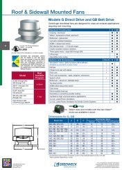
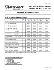
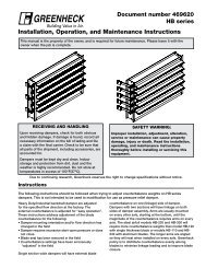
Performance Data<br />
Pressure Limitations<br />
20<br />
96<br />
16 15 in. w g<br />
on a maximum blade deflection of L/360.<br />
4000 fpm<br />
12<br />
Temperature 8.5 in. w g Limitations 72<br />
8<br />
<strong>Blade</strong> seals:<br />
4<br />
(-40° to 60 +204°C)<br />
0 0 12 24 36 48 60 72 (-29° to 48 +121°C) 5000 fpm<br />
Damper Width ( in.)<br />
Jamb seals:<br />
Pr essur e Limitations<br />
The chart at the right shows conservative pressure limitations based<br />
Silicone Rubber -40° to +400°F<br />
Damper Height ( in. )<br />
EPDM -20° to +250°F<br />
For higher temperatures consult <strong>Greenheck</strong><br />
Flexible stainless steel -40° to +400°F<br />
(-40° to +204°C)<br />
24<br />
Velocity Limitations<br />
The chart at far right shows conservative velocity limitations based<br />
on damper size.<br />
0<br />
12 36 48 60<br />
Damper Width ( in.)<br />
Ve locity Limitations<br />
Pr essur e ( in. w g)<br />
16<br />
12<br />
8.5 in. w g<br />
8<br />
4<br />
15 in. w g<br />
0 12 24 36 48<br />
Damper Width ( in.)<br />
Pr essur e Limitations<br />
<strong>220</strong><br />
Damper Height ( in.)<br />
96<br />
72<br />
60<br />
48<br />
36<br />
24<br />
12<br />
0<br />
<strong>HCD</strong>-<strong>220</strong><br />
3000 fpm<br />
3500 fpm<br />
4000 fpm<br />
12 24 36 48<br />
Damper Width ( in.)<br />
Ve locity Limitations<br />
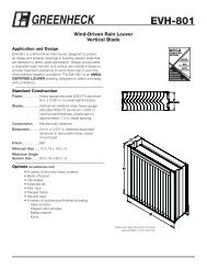
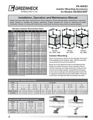
Pressure Drop Data<br />
This pressure drop data was conducted in accordance with AMCA Standard 500-D using the three configurations shown. All<br />
data has been corrected to represent standard air at a density of .075 lb/ft 3 (1.2 kg/m 3 ).<br />
Actual pressure drop found in any HVAC system is a combination of many factors. This pressure drop information along with an<br />
analysis of other system influences should be used to estimate actual pressure losses for a damper installed in a given HVAC<br />
system.<br />
AMCA Test Figures<br />
Figure 5.3 Illustrates a fully ducted damper. This configuration has the lowest pressure drop of the three test configurations<br />
because entrance and exit losses are minimized by straight duct runs upstream and downstream of the damper.<br />
Figure 5.2 Illustrates a ducted damper exhausting air into an open area. This configuration has a lower pressure drop than<br />
Figure 5.5 because the entrance losses are minimized by a straight duct run upstream of the damper.<br />
Figure 5.5 Illustrates a plenum mounted damper. This configuration has the highest pressure drop because of the high<br />
entrance and exit losses due to the sudden changes of area in the system.<br />
5D<br />
6D<br />
Fig. 5.3<br />
5D<br />
D=<br />
4 (W) (H)<br />
3.14<br />
Fig. 5.2<br />
Fig. 5.5
3<br />
performance data<br />
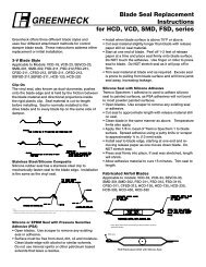
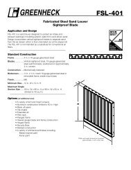
Leakage Data<br />
Static Pressure Difference (in. wg)<br />
Pr essur e Loss ( in. w g )<br />
15<br />
10<br />
9<br />
8<br />
7<br />
6<br />
5<br />
4<br />
3<br />
2<br />
1.0<br />
.9<br />
.8<br />
.7<br />
.6<br />
.5<br />
.4<br />
.3<br />
.2<br />
2.00<br />
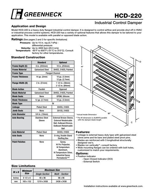
Pressure Drop<br />
36 in. x 36 in. (914mm x 914mm) Damper<br />
<strong>220</strong><br />
1.00<br />
.80<br />
.60<br />
.40<br />
.20<br />
.10<br />
.08<br />
.06<br />
.04<br />
.02<br />
.02<br />
2 3 4 5 6 7 8 9 10 2 3<br />
x 100 x 1000<br />
With Seals<br />
Velocity (fpm)<br />
120<br />
Without Seals<br />
1 2 3 4 5 6 7 8 910 20 30 4050 60 708090100 150<br />
Air Leakage in CFM/Sq. Ft.<br />
5. 5<br />
5 .2<br />
5 .3<br />
2 4 6 8 10 2 4<br />
x 100 x 1000<br />
Velocity (fpm)<br />
.02<br />
Pr essur e Loss ( in. w g )<br />
.6<br />
.5<br />
.4<br />
.3<br />
.2<br />
.10<br />
.09<br />
.08<br />
.07<br />
.06<br />
.05<br />
.04<br />
.03<br />
.0 2<br />
Static Pr essur e Dif fer ence (in. wg)<br />
Static Pr essur e Dif fer ence (in. wg)<br />
1. 0<br />
.9<br />
.8<br />
.7<br />
.6<br />
.5<br />
.4<br />
8. 5<br />
8<br />
7<br />
6<br />
5<br />
4<br />
3<br />
2<br />
1. 0<br />
.9<br />
.8<br />
.7<br />
.6<br />
.5<br />
.4<br />
.3<br />
.2<br />
2<br />
<strong>HCD</strong>-<strong>220</strong><br />
3 4 5 6 7 8 9 10 2 3 4<br />
x 100 x 1000<br />
Velocity (fpm)<br />
.3<br />
.2<br />
230/330<br />
1 2 3 4 5 6 7 8 9 10<br />
W ith S e a ls<br />
1 2 3 4 5 6 7 8 9 10<br />
Air Leakage in<br />
4 5 6 7 8 910<br />
2 3 4 5<br />
x 100 x 1000<br />
Velocity (fpm)<br />
Damper leakage (with blades fully closed) varies based on the type of low leakage seals applied. Model <strong>HCD</strong>-120 is available<br />
with no jamb seals (standard) or with stainless steel jamb seals and EPDM or silicone rubber blade seals. Leakage testing was<br />
conducted in accordance with AMCA Standard 500-D and is expressed as CFM per sq.ft. of damper face area. All data has<br />
been corrected to represent standard air at a density of .075 lb/ft 3 (1.2 kg/m 3 ).<br />
5.5<br />
5.2<br />
5.3<br />
13<br />
Air Leakage in<br />
Leakage<br />
36 in. x 36 in. (914mm x 914mm) Damper<br />
(based on 5 in. lb/ft 2 of torque)<br />
22 0<br />
230/3<br />
15<br />
15<br />
10<br />
9<br />
8<br />
7<br />
6<br />
10<br />
9<br />
8<br />
7<br />
6<br />
5<br />
5<br />
Static Pr essur e Dif fer ence (in. wg)<br />
4<br />
3<br />
2<br />
1. 0<br />
.9<br />
.8<br />
.7<br />
.6<br />
.5<br />
W it h S e a ls<br />
W it h o u t S e a ls<br />
Static Pr essur e Dif fer ence (in. wg)<br />
4<br />
3<br />
2<br />
1. 0<br />
.9<br />
.8<br />
.7<br />
.6<br />
.5<br />
W it h S e a ls<br />
.4<br />
.4<br />
.3<br />
.3<br />
.2<br />
.2<br />
1 2 3 4 5 6 7 8 910 20 30 40 50 60 70 80 90100 200<br />
Air Leakage in CFM/Sq. Ft.<br />
1 2 3 4 5 6 7 8 9 10<br />
Air Leakage in CFM/
BOLT HOLES<br />
<strong>HCD</strong>-<strong>220</strong><br />
Bolt holes are available as an option. <strong>Greenheck</strong>'s standard pattern is 7/16 in. (11mm) diameter holes (M dimension) spaced 6<br />
in. (152mm) on center (L dimension). Also, available is custom bolt hole pattern within the limitations of the chart below.<br />
Dim.<br />
W<br />
Standard<br />
-<br />
Formula<br />
-<br />
VARIABLE<br />
FORMULA<br />
Description<br />
W = DAMPER WIDTH<br />
Damper Width H = DAMPER HEIGHT<br />
D = FLANGE WIDTH<br />
H - - Damper Height L = HOLE SPACING STD. = 6<br />
D - - Flange WidthM = MOUNTING HOLE DIAMETER STD. = .4375<br />
Y = JAMB GAGE LINE D/2<br />
L 6 in.<br />
- Hole SpacingV = NO. OF SPACES IN HEAD/SILL INT((W-1.5)/L)<br />
(152mm)<br />
F = NO. OF SPACES IN JAMB INT((H+2*Y)/L)<br />
U = FIRST/LAST SPACE IN HEAD/SILL (W-(L*V))/2<br />
M 7/16 in.<br />
- Mounting Hole Diameter<br />
J = FIRST LAST SPACE IN JAMB (H+2*D-(L*F))/2<br />
(11mm)<br />
Y - D/2 Jamb Gauge Line<br />
V - INT((W-1.5)/L) Number of Spaces in Head/Sill<br />
F - INT((H+2*Y)/L) Number of Spaces in Jamb<br />
U - (W-(L*V))/2 First/Last Spce in Head/Sill<br />
J - (H+2*D - (L*F))/2 First Last Space in Jamb<br />
Specifications<br />
Industrial grade control dampers meeting the following<br />
specifications shall be furnished and installed where shown<br />
on plans and/or as described in schedules.<br />
Dampers shall consist of: a 14 ga. (2mm) galvanized steel<br />
channel frame with 8 in. (203mm) minimum depth and 2 in.<br />
(51mm) flanges; 3V type blades fabricated from 12 ga. (2.7mm)<br />
galvanized steel; 3 ⁄4 in. (19mm) dia. plated steel axles turning<br />
in stainless steel sleeve bearings; and external (out of the<br />
airstream) blade-to-blade linkage.<br />
Damper manufacturer's printed application and performance<br />
data including pressure, velocity and temperature limitations<br />
shall be submitted for approval showing damper suitable for<br />
pressures to 15 in. wg (3.7 kPa), velocities to 4000 fpm<br />
(20.3 m/s) and temperatures to 1500°F (816°C). Testing<br />
and ratings to be in accordance with AMCA Standard<br />
500-D.<br />
Specifier may add the following:<br />
Dampers shall be equipped with blade and jamb seals<br />
for low leakage performance. <strong>Blade</strong> seals shall be: select<br />
one of the following EPDM synthetic rubber for 250°F<br />
(121°C) maximum temperature, or Silicone Rubber for<br />
400°F (204°C) maximum temperature. Jamb seals shall be<br />
flexible stainless steel.<br />
Basis of design is <strong>Greenheck</strong> model <strong>HCD</strong>-<strong>220</strong>.<br />
Copyright © 2013 <strong>Greenheck</strong> Fan Corporation<br />
<strong>HCD</strong>-<strong>220</strong> Rev. 11 Sept 2013