motor-driver
motor-driver
motor-driver
You also want an ePaper? Increase the reach of your titles
YUMPU automatically turns print PDFs into web optimized ePapers that Google loves.
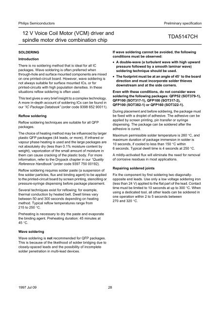
Philips Semiconductors<br />
12 V Voice Coil Motor (VCM) <strong>driver</strong> and<br />
spindle <strong>motor</strong> drive combination chip<br />
Preliminary specification<br />
TDA5147CH<br />
SOLDERING<br />
Introduction<br />
There is no soldering method that is ideal for all IC<br />
packages. Wave soldering is often preferred when<br />
through-hole and surface mounted components are mixed<br />
on one printed-circuit board. However, wave soldering is<br />
not always suitable for surface mounted ICs, or for<br />
printed-circuits with high population densities. In these<br />
situations reflow soldering is often used.<br />
This text gives a very brief insight to a complex technology.<br />
A more in-depth account of soldering ICs can be found in<br />
our “IC Package Databook” (order code 9398 652 90011).<br />
Reflow soldering<br />
Reflow soldering techniques are suitable for all QFP<br />
packages.<br />
The choice of heating method may be influenced by larger<br />
plastic QFP packages (44 leads, or more). If infrared or<br />
vapour phase heating is used and the large packages are<br />
not absolutely dry (less than 0.1% moisture content by<br />
weight), vaporization of the small amount of moisture in<br />
them can cause cracking of the plastic body. For more<br />
information, refer to the Drypack chapter in our “Quality<br />
Reference Handbook” (order code 9397 750 00192).<br />
Reflow soldering requires solder paste (a suspension of<br />
fine solder particles, flux and binding agent) to be applied<br />
to the printed-circuit board by screen printing, stencilling or<br />
pressure-syringe dispensing before package placement.<br />
Several techniques exist for reflowing; for example,<br />
thermal conduction by heated belt. Dwell times vary<br />
between 50 and 300 seconds depending on heating<br />
method. Typical reflow temperatures range from<br />
215 to 250 °C.<br />
Preheating is necessary to dry the paste and evaporate<br />
the binding agent. Preheating duration: 45 minutes at<br />
45 °C.<br />
If wave soldering cannot be avoided, the following<br />
conditions must be observed:<br />
• A double-wave (a turbulent wave with high upward<br />
pressure followed by a smooth laminar wave)<br />
soldering technique should be used.<br />
• The footprint must be at an angle of 45° to the board<br />
direction and must incorporate solder thieves<br />
downstream and at the side corners.<br />
Even with these conditions, do not consider wave<br />
soldering the following packages: QFP52 (SOT379-1),<br />
QFP100 (SOT317-1), QFP100 (SOT317-2),<br />
QFP100 (SOT382-1) or QFP160 (SOT322-1).<br />
During placement and before soldering, the package must<br />
be fixed with a droplet of adhesive. The adhesive can be<br />
applied by screen printing, pin transfer or syringe<br />
dispensing. The package can be soldered after the<br />
adhesive is cured.<br />
Maximum permissible solder temperature is 260 °C, and<br />
maximum duration of package immersion in solder is<br />
10 seconds, if cooled to less than 150 °C within<br />
6 seconds. Typical dwell time is 4 seconds at 250 °C.<br />
A mildly-activated flux will eliminate the need for removal<br />
of corrosive residues in most applications.<br />
Repairing soldered joints<br />
Fix the component by first soldering two diagonallyopposite<br />
end leads. Use only a low voltage soldering iron<br />
(less than 24 V) applied to the flat part of the lead. Contact<br />
time must be limited to 10 seconds at up to 300 °C. When<br />
using a dedicated tool, all other leads can be soldered in<br />
one operation within 2 to 5 seconds between<br />
270 and 320 °C.<br />
Wave soldering<br />
Wave soldering is not recommended for QFP packages.<br />
This is because of the likelihood of solder bridging due to<br />
closely-spaced leads and the possibility of incomplete<br />
solder penetration in multi-lead devices.<br />
1997 Jul 09 28


