motor-driver
motor-driver
motor-driver

You also want an ePaper? Increase the reach of your titles
YUMPU automatically turns print PDFs into web optimized ePapers that Google loves.
Philips Semiconductors<br />
12 V Voice Coil Motor (VCM) <strong>driver</strong> and<br />
spindle <strong>motor</strong> drive combination chip<br />
Preliminary specification<br />
TDA5147CH<br />
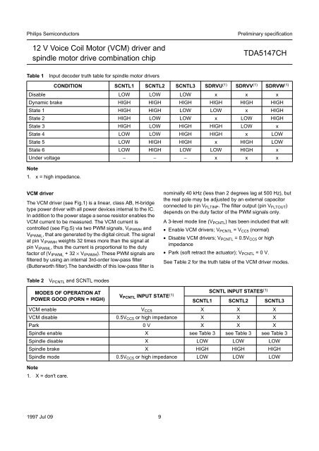
Table 1<br />
Input decoder truth table for spindle <strong>motor</strong> <strong>driver</strong>s<br />
CONDITION SCNTL1 SCNTL2 SCNTL3 SDRVU (1) SDRVV (1) SDRVW (1)<br />
Disable LOW LOW LOW x x x<br />
Dynamic brake HIGH HIGH HIGH HIGH HIGH HIGH<br />
State 1 HIGH HIGH LOW LOW x HIGH<br />
State 2 HIGH LOW LOW x LOW HIGH<br />
State 3 HIGH LOW HIGH HIGH LOW x<br />
State 4 LOW LOW HIGH HIGH x LOW<br />
State 5 LOW HIGH HIGH x HIGH LOW<br />
State 6 LOW HIGH LOW LOW HIGH x<br />
Under voltage − − − x x x<br />
Note<br />
1. x = high impedance.<br />
VCM <strong>driver</strong><br />
The VCM <strong>driver</strong> (see Fig.1) is a linear, class AB, H-bridge<br />
type power <strong>driver</strong> with all power devices internal to the IC.<br />
In addition to the power stage a sense resistor enables the<br />
VCM current to be measured. The VCM current is<br />
controlled (see Fig.5) via two PWM signals, V IPWMH and<br />
V IPWML , that are generated by the digital circuit. The signal<br />
at pin V IPWMH weights 32 times more than the signal at<br />
pin V IPWML , thus the current is proportional to the duty<br />
factor of (V IPWML +32×V IPWMH ). These PWM signals are<br />
filtered by using an internal 3rd-order low-pass filter<br />
(Butterworth filter).The bandwidth of this low-pass filter is<br />
nominally 40 kHz (less than 2 degrees lag at 500 Hz), but<br />
the real pole may be adjusted by an external capacitor<br />
connected to pin V FLTINP . The filter output (pin V FLTOUT )<br />
depends on the duty factor of the PWM signals only.<br />
A 3-level mode line (V PCNTL ) has been included that will:<br />
• Enable VCM <strong>driver</strong>s; V PCNTL =V CC5 (normal)<br />
• Disable VCM <strong>driver</strong>s; V PCNTL = 0.5V CC5 or high<br />
impedance<br />
• Park (soft retract the actuator); V PCNTL =0V.<br />
See Table 2 for the truth table of the VCM <strong>driver</strong> modes.<br />
Table 2<br />
V PCNTL and SCNTL modes<br />
MODES OF OPERATION AT<br />
SCNTL INPUT STATES (1)<br />
V<br />
POWER GOOD (PORN = HIGH) PCNTL INPUT STATE (1) SCNTL1 SCNTL2 SCNTL3<br />
VCM enable V CC5 X X X<br />
VCM disable 0.5V CC5 or high impedance X X X<br />
Park 0 V X X X<br />
Spindle enable X see Table 3 see Table 3 see Table 3<br />
Spindle disable X LOW LOW LOW<br />
Spindle brake X HIGH HIGH HIGH<br />
Spindle mode 0.5V CC5 or high impedance LOW LOW LOW<br />
Note<br />
1. X = don't care.<br />
1997 Jul 09 9