motor-driver
motor-driver
motor-driver
You also want an ePaper? Increase the reach of your titles
YUMPU automatically turns print PDFs into web optimized ePapers that Google loves.
Philips Semiconductors<br />
12 V Voice Coil Motor (VCM) <strong>driver</strong> and<br />
spindle <strong>motor</strong> drive combination chip<br />
Preliminary specification<br />
TDA5147CH<br />
FUNCTIONAL DESCRIPTION<br />
Spindle <strong>driver</strong>s<br />
The spindle section (see Fig.2) contains both the low and<br />
high side <strong>driver</strong>s (configured as H bridges) for a<br />
three-phase DC brushless <strong>motor</strong>. Back EMF (Electro<br />
Motive Force) sensing of the commutation rate<br />
(pin SENWIS) is an output to an external digital ASIC<br />
circuit. This circuit should provide the input commutation<br />
control as well. Consequently, all speed control, start-up<br />
routine and commutation control will be generated by the<br />
external digital circuit.<br />
The SIPWM signal from the digital circuit is used to control<br />
the spindle current. This PWM signal is internally filtered.<br />
The output of this filter depends solely on the duty factor.<br />
The pole location of this first order low-pass filter is<br />
controlled by an external capacitor at pin SPWMFLT.<br />
Dynamic braking is possible only during non power-down<br />
situations and must be initiated by the digital circuit.<br />
A 3- level mode line (pin SMODE1) allows for:<br />
• Induction sensing in pre-start-up (SMODE1 = 0.5V CC5<br />
or high impedance)<br />
• PWM control during start-up (SMODE1 = 0 V)<br />
• Linear control (SMODE1 = V CC5 ).<br />
SENSING MODE<br />
The induction sensing mode can be used to sense the<br />
rotor position and to spin-up with high current.<br />
To sense the rotor position, one of the BEMF sensor<br />
outputs (pin SENWIS) will be shared with the voltage<br />
comparator that is used for the induction sensing function.<br />
Prior to start-up each phase is excited for a short period of<br />
time. The current from each coil can be monitored via the<br />
multiplexed output (SENWIS). By comparing the rise times<br />
of each phase the rotor position can be determined.<br />
In cases where the spindle <strong>motor</strong> requires more current to<br />
spin-up, the sensing mode is used with the exception that<br />
the output SENWIS is ignored. The output <strong>driver</strong>s are<br />
operated in saturation in the sensing mode, so the <strong>motor</strong><br />
current is only limited by the power supply. This condition<br />
of induction sense mode can be used to overcome the<br />
head friction and must only be used when needed.<br />
PWM MODE<br />
The PWM mode is normally used during the start-up<br />
phase. Maximum drive voltage is applied to the low <strong>driver</strong>s<br />
to obtain high start-up torque. The purpose of the PWM<br />
mode is to drive the low <strong>driver</strong>s into saturation, because<br />
saturation reduces the power dissipation during start-up.<br />
When the spindle current reaches the value destined by<br />
the duty factor of the signal at pin SIPWM, a one-shot is<br />
fired. The output of the one-shot remains HIGH for the<br />
programmed off-time (t off ) set by the RC-network at<br />
pin SPWMTC. The one-shot is not retriggerable for<br />
approximately 10% of the off-time, giving a minimum for<br />
the on-time of 0.1t off . During the off-time, the lower spindle<br />
output <strong>driver</strong>s are switched off. The on-time of the <strong>driver</strong>s<br />
is determined by the charging time of the coil current.<br />
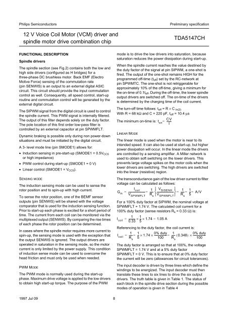
The turn-off time follows: t off =R×C ln(2)<br />
With R = 68 kΩ and C = 220 pF, t off = 10.4 µs<br />
The minimum on-time is:<br />
LINEAR MODE<br />
t on<br />
CV<br />
--------<br />
I<br />
The linear mode is used when the <strong>motor</strong> is near to its<br />
intended speed. It can also be used at start-up, but higher<br />
power dissipation will occur. In the linear mode the <strong>driver</strong>s<br />
are controlled by a sensing amplifier. A Miller network is<br />
used to obtain soft switching on the lower <strong>driver</strong>s. This<br />
prevents large voltage spikes on the <strong>motor</strong> coils when the<br />
lower <strong>driver</strong>s are switching. The high <strong>driver</strong>s are switched<br />
into the linear (resistive) region.<br />
The transconductance gain of the low <strong>driver</strong> current to filter<br />
voltage can be calculated as follows:<br />
I coil 1 ⎧ V SISENH<br />
⎫ 1 1<br />
G m<br />
= --------------------------- = ------ ⎨---------------------------<br />
⎬=<br />
------ = -- = A/V<br />
⎩ ⎭ 5<br />
V SPWMFLT<br />
R s<br />
For a 100% duty factor at SIPWM, the nominal voltage at<br />
SPWMFLT = 1.74 V. The calculated coil current for a<br />
100% duty factor (sense resistors R s = 0.33 Ω) is:<br />
Referencing to the duty factor, the coil current is:<br />
The duty factor is arranged so that at 100%, the voltage<br />
SPWMFLT = 1.74 V and at a 5% duty factor<br />
SPWMFLT = 0 V. This is to ensure that at 0% duty factor<br />
the current will be zero (allowances for circuit tolerances).<br />
The input decoder is driven by three lines which define the<br />
windings to be energized. The input decoder must then<br />
translate these lines to six lines to drive the six output<br />
<strong>driver</strong>s. The truth table is given in Table 1. The status of<br />
each block in the spindle drive section during the possible<br />
modes of operation is given in Table 4<br />
=<br />
V SPWMFLT<br />
1 1<br />
I coil<br />
= ---------- × -- × 1.74 = 1.05 A<br />
0.33 5<br />
1<br />
I coil<br />
= ------ =<br />
R s<br />
1<br />
-- × 1.74<br />
5<br />
0% duty<br />
× --------------------<br />
100<br />
=<br />
R s<br />
R s<br />
1<br />
0% duty<br />
------ ( 0.348)<br />
× --------------------<br />
100<br />
1997 Jul 09 8


