Short description protocol ES40 - Krohne
Short description protocol ES40 - Krohne
Short description protocol ES40 - Krohne
You also want an ePaper? Increase the reach of your titles
YUMPU automatically turns print PDFs into web optimized ePapers that Google loves.
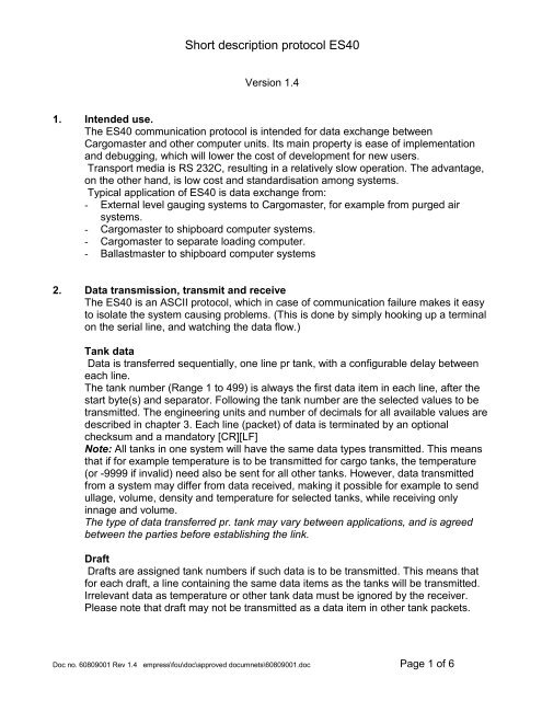
<strong>Short</strong> <strong>description</strong> <strong>protocol</strong> <strong>ES40</strong><br />
Version 1.4<br />
1. Intended use.<br />
The <strong>ES40</strong> communication <strong>protocol</strong> is intended for data exchange between<br />
Cargomaster and other computer units. Its main property is ease of implementation<br />
and debugging, which will lower the cost of development for new users.<br />
Transport media is RS 232C, resulting in a relatively slow operation. The advantage,<br />
on the other hand, is low cost and standardisation among systems.<br />
Typical application of <strong>ES40</strong> is data exchange from:<br />
- External level gauging systems to Cargomaster, for example from purged air<br />
systems.<br />
- Cargomaster to shipboard computer systems.<br />
- Cargomaster to separate loading computer.<br />
- Ballastmaster to shipboard computer systems<br />
2. Data transmission, transmit and receive<br />
The <strong>ES40</strong> is an ASCII <strong>protocol</strong>, which in case of communication failure makes it easy<br />
to isolate the system causing problems. (This is done by simply hooking up a terminal<br />
on the serial line, and watching the data flow.)<br />
Tank data<br />
Data is transferred sequentially, one line pr tank, with a configurable delay between<br />
each line.<br />
The tank number (Range 1 to 499) is always the first data item in each line, after the<br />
start byte(s) and separator. Following the tank number are the selected values to be<br />
transmitted. The engineering units and number of decimals for all available values are<br />
described in chapter 3. Each line (packet) of data is terminated by an optional<br />
checksum and a mandatory [CR][LF]<br />
Note: All tanks in one system will have the same data types transmitted. This means<br />
that if for example temperature is to be transmitted for cargo tanks, the temperature<br />
(or -9999 if invalid) need also be sent for all other tanks. However, data transmitted<br />
from a system may differ from data received, making it possible for example to send<br />
ullage, volume, density and temperature for selected tanks, while receiving only<br />
innage and volume.<br />
The type of data transferred pr. tank may vary between applications, and is agreed<br />
between the parties before establishing the link.<br />
Draft<br />
Drafts are assigned tank numbers if such data is to be transmitted. This means that<br />
for each draft, a line containing the same data items as the tanks will be transmitted.<br />
Irrelevant data as temperature or other tank data must be ignored by the receiver.<br />
Please note that draft may not be transmitted as a data item in other tank packets.<br />
Doc no. 60809001 Rev 1.4 empress\fou\doc\approved documnets\60809001.doc Page 1 of 6
Error indication<br />
Invalid data is indicated by sending -9999 in the data field, for example after failure of<br />
a transducer or lack of user input data.<br />
Cargo line pressure<br />
Tank numbers above 900 are used to indicate load-line pressure data rather than tank<br />
data. 900 is added to the line pressure number before transmission, and the only data<br />
transmitted is pressure and, optionally, alarm status. The format of the data packets<br />
containing cargo line pressure will vary from the format of the tank data packets.<br />
System data<br />
As an option at the beginning of each transmit cycle, system data (trim, list, and<br />
atmospheric pressure) may be transferred on a separate line. The format of this data<br />
packet is fixed, and is indicated by setting zero in the tank no field.<br />
Data transmitted will be:<br />
[start][sep]0[sep]Trim[sep]List[sep]Atmospheric pressure.<br />
The start byte(s), separator and optional check sum will be used as globally configured<br />
for the system.<br />
The example in chapter 5 includes the system packet.<br />
Start byte(s).<br />
The start-byte is configurable. It is strongly recommended to use a printable character<br />
in the decimal ASCII range 33 to 42, or ASCII 64. The default is ASCII 64 (@).<br />
The number of start bytes is also configurable to allow for synchronisation bytes,<br />
please pay attention to the checksum <strong>description</strong> below when using multiple start<br />
bytes.<br />
Separator<br />
One separator is used between data items. The byte may be configured using the<br />
same guidelines as for the start byte, but the ASCII value of the start and separator<br />
byte may not take the same value. The default separator is space (ASCII 32), which is<br />
strongly recommended.<br />
The separator byte is inserted between all data items, also between the start byte and<br />
the tank no, but not before the [CR][LF] packet terminator.<br />
Stop bytes.<br />
To terminate each data packet, [CR][LF] is always used.<br />
Checksum.<br />
The use of checksum is optional. If used, the checksum is the eight bit sum of all<br />
preceding characters on the same line. Regardless of the number of start bytes used,<br />
only one start byte is to be used for checksum calculation. The [CR][LF] packet<br />
terminator is succeeding the checksum, and is therefore not included in the<br />
calculation.<br />
The decimal value of the checksum is transmitted as three ASCII characters in order<br />
to avoid non-printable characters in the telegram.<br />
The examples in chapter 5 include calculated checksum.<br />
Doc no. 60809001 Rev 1.4 empress\fou\doc\approved documnets\60809001.doc Page 2 of 6
3. Units.<br />
Units for data transfer are:<br />
Temperature: 0C with one decimal (Tank average or any sensor temp)<br />
Draft: Meters with three decimals (Specify as level)<br />
Innage (flot.lev): Meters with three decimals (Level in flotation centre)<br />
Innage (level): Meters with three decimals (Level at manual ref. point)<br />
Ullage: Meters with three decimals (Ullage at manual ullage hatch)<br />
Inert gas pressure: mmWg with no decimals<br />
Weight: Metric ton with three decimals.<br />
Volume: m3 with three decimals<br />
Volume % of full: % with two decimals<br />
Ref. temperature: 0C with one decimal (Ref. temperature 1 or 2 from operator)<br />
Density: Density in air with five decimals, t/m3 (Actual dens., measured dens. or any operator input dens.)<br />
Density coefficient: Density change pr. 0C with five decimals, t/(m3 0C) Loadrate: m3 /h with one decimal<br />
Tank name: String of max. 8 characters<br />
Pressure: mmWg with no decimals for any tank pressure sensor.<br />
Tank type:<br />
First byte:<br />
Two consecutive bytes (No separator between bytes):<br />
Bit 7 - 0<br />
Bit 6 - 1<br />
Bit 5 - 1 = Variable solid (Load calculator only)<br />
Bit 4 - 1 = Constant solid (Load calculator only)<br />
Bit 3 - 1 = Misc. tank<br />
Bit 2 - 1 = Fuel tank<br />
Bit 1 - 1 = Ballast tank<br />
Bit 0 - 1 = CARGO tank<br />
Second byte:<br />
Bit 7 - 0<br />
Bit 6 - 1<br />
Bit 5 - Density display type *)<br />
Bit 4 - Density display type *)<br />
Bit 3 - Density display type *)<br />
Bit 2 - 1 = Online tank / 0 = Offline tank<br />
Bit 1 - 1 = Temp. tank<br />
Bit 0 - 1 = Draft tank<br />
*) Density display type:<br />
0 = Linear (Density @15 0 C and coefficient)<br />
1 = API CRUDE<br />
2 = API PRODUCT<br />
3 = API LUB OIL<br />
4 = API BALLAST<br />
5 = ASTM54b<br />
6 = Future use<br />
7 = Future use<br />
Doc no. 60809001 Rev 1.4 empress\fou\doc\approved documnets\60809001.doc Page 3 of 6
Alarm status: Three consecutive bytes (No separator between bytes):<br />
First byte:<br />
Bit 7 - 0<br />
Bit 6 - 1<br />
Bit 5 - Future use<br />
Bit 4 - 1 = Horn on (Set to 1 if horn is on)<br />
Bit 3 - 1 = Sensor disabled<br />
Bit 2 - 1 = Hardware error on tank/line measurement<br />
Bit 1 - 1 = Alarm active (Active =1, Acknowledged=0)<br />
Bit 0 - 1 = Any alarm (active or acknowledged) in tank/line-pressure<br />
Second byte:<br />
Bit 7 - 0<br />
Bit 6 - 1<br />
Bit 5 - 1 = High High level<br />
Bit 4 - 1 = High level<br />
Bit 3 - 1 = Low level<br />
Bit 2 - 1 = Low Low level<br />
Bit 1 - 1 = High inert pressure (High pressure for line pressure)<br />
Bit 0 - 1 = Low inert pressure (Low pressure for line pressure)<br />
Third byte:<br />
Bit 7 - 0<br />
Bit 6 - 1<br />
Bit 5 - Future use<br />
Bit 4 - Future use<br />
Bit 3 - Future use<br />
Bit 2 - 1 = High temperature<br />
Bit 1 - 1 = Low temperature<br />
Bit 0 - 1 = Density difference (Deviation manual/measured density)<br />
Line pressure: mmWg with no decimals<br />
Atmospheric press.: mmWg with no decimals<br />
Trim: Degrees (360) with five decimals, Negative aft<br />
List: Degrees (360) with five decimals, Negative port<br />
Note:<br />
All above values are valid for output from Cargomaster. The following values are valid for<br />
input, taking the same units and number of decimals as for output:<br />
Ullage Volume Vol% Temperature (Average only)<br />
Inert press Density (As output) Density expansion Atmospheric pressure<br />
Level (Flot.) Dens. ref. temps. Trim List<br />
Level (Ref. Pt.)<br />
Doc no. 60809001 Rev 1.4 empress\fou\doc\approved documnets\60809001.doc Page 4 of 6
4. Handshaking, data format and speed.<br />
The <strong>protocol</strong> uses no handshaking or control flow signals. Neither is there a need to<br />
request data, as each sender transmits the agreed data sequentially in an endless<br />
loop.<br />
This means that an ASCII terminal (or a PC with terminal emulator) can be hooked up<br />
on the line to check the data flow from each node in the system. (RX, TX and ground<br />
are the only lines connected.)<br />
Hardware data format:<br />
Speed: 300 to 19200 Baud. Default 9600 Baud<br />
Stop bits: 1 or 2. Default 1<br />
Start bits: 1<br />
Parity: Odd/even/none Default none<br />
Packet delay.<br />
The delay between each line(packet) of data is configurable. A typical system will<br />
delay 0.3 seconds between the start of each line.<br />
5. Example.<br />
A typical sequence (Start byte=$, Separator=space, Checksum included) to transmit:<br />
System data<br />
Innage, ullage, volume, volume%, inert pressure, 4 temperatures for tank 1 to 5<br />
Line pressure points 1 to 4<br />
$ 0 -0.06356 0.08881 9200 181<br />
$ 1 0.000 14.574 0.000 0.00 6 25.4 25.5 25.4 25.4 221<br />
$ 2 0.000 14.582 0.000 0.00 -14 25.2 25.3 25.2 25.2 049<br />
$ 3 0.000 14.566 0.000 0.00 9 -9999.0 -9999.0 -9999.0 25.2 210<br />
$ 4 0.000 14.570 0.000 0.00 3 -9999.0 -9999.0 -9999.0 25.2 200<br />
$ 5 0.000 14.560 0.000 0.00 -10 -9999.0 -9999.0 -9999.0 25.2 035<br />
$ 901 6617 242<br />
$ 902 7189 248<br />
$ 903 7786 252<br />
$ 904 9112 238<br />
Detail of the first line of the above telegram:<br />
$ 0 - 0 . 0 6 3 5 6 0 . 0 8 8 8 1 9 2 0 0 1 8 1 CR LF<br />
The above cycle will be transmitted in an endless loop.<br />
Doc no. 60809001 Rev 1.4 empress\fou\doc\approved documnets\60809001.doc Page 5 of 6
6. Options<br />
As implemented by Scana Skarpenord, the above <strong>protocol</strong> may be substituted by the<br />
Simrad "Standard AVM" <strong>protocol</strong>. The implementation will generate one line (packet)<br />
of data pr tank, and treats the tank number as an analogue value. In all other aspects<br />
(i.e error indication, separators, checksum etc.) the Simrad AVM <strong>protocol</strong> <strong>description</strong><br />
(Doc.no.sa13304) is followed.<br />
Langesund, Sep 10. 1999<br />
H.Hogner<br />
Doc no. 60809001 Rev 1.4 empress\fou\doc\approved documnets\60809001.doc Page 6 of 6


