Test set-up CoMeT - Bmund.de
Test set-up CoMeT - Bmund.de
Test set-up CoMeT - Bmund.de

Create successful ePaper yourself
Turn your PDF publications into a flip-book with our unique Google optimized e-Paper software.
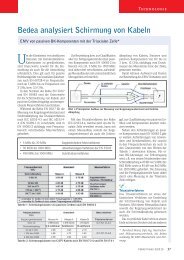
e<strong>de</strong>a – Rosenberger<br />
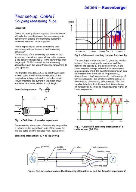
<strong>Test</strong> <strong>set</strong>-<strong>up</strong> <strong>CoMeT</strong><br />
Co<strong>up</strong>ling Measuring Tube<br />
log|T|<br />
General:<br />
Due to increasing electromagnetic disturbances of<br />
all kinds, the investigation of the electromagnetic<br />
behaviour of electric and electronic equipment<br />
becomes more and more important.<br />
This is especially for cables concerning their<br />
electromagnetic performance and screening<br />
behaviour.<br />
The measure of the screening behaviour of the<br />
screens of coaxial and symmetrical cable screens<br />
is the transfer impedance Z T in the lower frequency<br />
range <strong>up</strong> to 50 MHz as well as the screening<br />
attenuation a S in the <strong>up</strong>per frequency range from 30<br />
MHz <strong>up</strong>wards.<br />
The transfer impedance Z T of an electrically short<br />
uniform cable is <strong>de</strong>fined as the quotient of the<br />
longitudinal voltage induced in the outer circuit<br />
(environment) to the current in the inner circuit<br />
(cable) or vice versa, related to unit length.<br />
Transfer impedance:<br />
Z<br />
T<br />
U2<br />
=<br />
I ⋅ L<br />
1<br />
T f<br />
T n<br />
10 kHz 100 1 MHz 10 MHz f cn f cf 1 GHz 10 G<br />
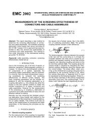
Fig. 2 - Calculated co<strong>up</strong>ling transfer function T n,f<br />
The co<strong>up</strong>ling transfer function T n,f gives the relation<br />
between the screening attenuation a S and the<br />
transfer impedance Z T of a cables screen. In the<br />
lower frequency range, where the cable samples<br />
are electrically short, the transfer impedance Z T can<br />
be measured <strong>up</strong> to the cut off frequencies f cn,f .<br />
Above these cut off frequencies f cn,f in the range of<br />
wave propagation, the screening attenuation a S is<br />
the measure of screening effectiveness. With the<br />
variable tube length of the new test fixture the cut<br />
off frequencies f cn,f may be moved towards higher or<br />
lower frequencies.<br />
l<br />
40<br />
-46 dB<br />
U 2<br />
60<br />
U 1<br />
I 1 U 2<br />
80<br />
Fig. 1 - Definition of transfer impedance<br />
The screening attenuation of electrically long cables<br />
is <strong>de</strong>fined as the logarithmic ratio of the power fed<br />
into the cable and the radiated max. peak power:<br />
100<br />
0 500 1000 1500 2000<br />
Fig. 3 - Calculated screening attenuation of a<br />
cable screen (RG 058)<br />
screening attenuation: a S = 10 log (P 1 /P 2 )<br />
generator<br />
screen<br />
un<strong>de</strong>r test<br />
tube<br />
matching resistor<br />
receiver<br />
screening case<br />
Fig. 4 - <strong>Test</strong> <strong>set</strong>-<strong>up</strong> to measure the Screening attenuation a S and the Transfer impedance Z T
e<strong>de</strong>a – Rosenberger<br />
Up to now, the measure of the transfer<br />
impedance Z T and the screening attenuation<br />
a s required two measuring <strong>set</strong>-<strong>up</strong>s, e.g. the<br />
triaxial test <strong>set</strong> <strong>up</strong> and the absorbing clamp<br />
<strong>set</strong> <strong>up</strong>.<br />
With the new measuring tube <strong>CoMeT</strong> both,<br />
the transfer impedance Z T in the lower<br />
frequency range as well as the screening<br />
attenuation a S in the higher frequency range<br />
<strong>up</strong> to more than 8 GHz (12 GHz) can be<br />
measured. Furthermore, measurements of<br />
the co<strong>up</strong>ling attenuation a C of screened<br />
balanced cables which is the sum of<br />
unbalance attenuation of the pairs and the<br />
screening attenuation of the screen can be<br />
taken.<br />
With the new measuring tube <strong>CoMeT</strong> and<br />
appropriate networkanalysers or discrete generator<br />
and receiver measuring arrangements in<br />
accordance with several national, regional and<br />
international standards may be realised.<br />
Due to the shiel<strong>de</strong>d measuring fixture screening<br />
attenuation values of more than 125 dB<br />
respectively transfer impedances in the µ-Ohm<br />
range may be measured easily.<br />
Measure of:<br />
- Transfer impedance<br />
- Screening attenuation<br />
- Co<strong>up</strong>ling attenuation<br />
Advantages:<br />
• insensitive against electromagnetic<br />
disturbances from outsi<strong>de</strong><br />
• no radiation of electromagnetic power<br />
• high dynamic range > 125 dB<br />
• high reproducibility<br />
• simple measuring <strong>set</strong>-<strong>up</strong><br />
• fast preparing of the cable sample<br />
• only one measurement required<br />
• measure of the screening attenuation a S and<br />
the transfer impedance Z T with one test fixture.
e<strong>de</strong>a – Rosenberger<br />
Cut off frequencies:<br />
The <strong>up</strong>per cut off frequency results from the<br />
<strong>de</strong>finition of the wave propagation of transversal<br />
electromagnetic waves (TEM-waves) which is given<br />
by:<br />
2⋅c<br />
f<br />
g<br />
=<br />
0<br />
π⋅ ε ⋅ D + d<br />
( )<br />
r2 2 1<br />
where d 1 is the outer diameter of the braid of the<br />
CUT, D 2 is the inner diameter of the measuring<br />
tube and ε r2 is the resulting dielectric permittivity of<br />
the outer system.<br />
With an inner diameter of 40 mm of the tube and an<br />
outer diameter of about 3,5 mm of the braid, the cut<br />
off frequency of the system is about 4,2 GHz.<br />
The lower cut off frequency to measure the<br />
screening attenuation a S (electrical long cables)<br />
and the <strong>up</strong>per frequency limit to measure the<br />
transfer impedance Z T (electrical short cables) are<br />
given by the <strong>de</strong>finition of electrically long and<br />
electrically short by:<br />
electrically long:<br />
Standards:<br />
With the co<strong>up</strong>ling measuring tube <strong>CoMeT</strong><br />
measurements of the screening attenuation a S , the<br />
co<strong>up</strong>ling attenuation a C and the transfer impedance<br />
Z T may be achieved according the following<br />
national, regional and international standards:<br />
IEC 62153-4-x series: Metallic communication<br />
cable test methods - Part 4 -x: Electro Magnetic<br />
Compatibility (EMC)<br />
• IEC 62153-4-3: Surface transfer impedance -<br />
Triaxial method<br />
• IEC 62153-4-4: Shiel<strong>de</strong>d screening attenuation,<br />
test method for measuring of the screening<br />
attenuation "a s " <strong>up</strong> to and above 3 GHz<br />
• IEC 62153-4-7: Shiel<strong>de</strong>d screening attenuation,<br />
test method for measuring the Transfer<br />
impedance Z T and the screening attenuation a S<br />
of RF-Connectors and assemblies <strong>up</strong> to and<br />
above 3 GHz,Tube in Tube method<br />
• IEC 62153-4-9, (IEC/PAS 62338 Ed1):<br />
Co<strong>up</strong>ling attenuation (balanced cables), Triaxial<br />
method<br />
λo<br />
≤2<br />
⋅ εr1−<br />
ε<br />
l<br />
co<br />
f ><br />
2 ⋅ l ⋅ ε − ε<br />
r1<br />
resp. electrically short:<br />
λ<br />
> 10 ⋅<br />
l<br />
co<br />
f <<br />
10 ⋅ l ⋅ ε<br />
o ε r1<br />
r1<br />
r2<br />
r2<br />
or<br />
or<br />
regional: (Europa)<br />
• EN 50289-1-6: Surface transfer impedance -<br />
Triaxial method<br />
• EN 50289-1-6: Shiel<strong>de</strong>d screening attenuation,<br />
test method for measuring of the screening<br />
attenuation "a s " <strong>up</strong> to and above 3 GHz<br />
national: (Germany):<br />
• VG 95214-12: Messverfahren für <strong>de</strong>n<br />
Kopplungswi<strong>de</strong>rstand und die Schirmdämpfung<br />
von geschirmten Bauelementen, Teil 12:<br />
Messverfahren KS 12 B, Kopplungswi<strong>de</strong>rstand,<br />
Triaxialverfahren,<br />
where<br />
l<br />
λo<br />
ε<br />
ε<br />
f<br />
r1<br />
r2<br />
co<strong>up</strong>ling length in the tube<br />
wave length of free space<br />
dielectric permittivity of the CUT<br />
dielectric permittivity of the outer<br />
system<br />
frequency in Hz<br />
Due to the variable length of the tube, the<br />
frequency limits may be varied in a wi<strong>de</strong> range.<br />
• VG 95214-13: Messverfahren für <strong>de</strong>n<br />
Kopplungswi<strong>de</strong>rstand und die Schirmdämpfung<br />
von geschirmten Bauelementen, Teil 13:<br />
Messverfahren KS 13 B, Schirmdämpfung,<br />
Triaxialverfahren.<br />
A standard for measuring the screening<br />
effectiveness of larger connectors as well as of<br />
connecting hardware is un<strong>de</strong>r consi<strong>de</strong>ration at<br />
IEC TC 46/WG 5.
e<strong>de</strong>a – Rosenberger<br />
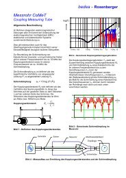
Co<strong>up</strong>ling attenuation<br />
The screening effectiveness respectively the<br />
electromagnetic performance of screened<br />
symmetrical pairs is given by the "co<strong>up</strong>ling<br />
attenuation", which is the sum of the<br />
unbalance attenuation of the pair and the<br />
screening attenuation of the screen.<br />
With the co<strong>up</strong>ling measuring tube <strong>CoMeT</strong> the<br />
co<strong>up</strong>ling attenuation a C of screened symmetrical<br />
pairs can be measured when the pair is fed in the<br />
differential mo<strong>de</strong>.<br />
screen un<strong>de</strong>r test<br />
generator<br />
co<strong>up</strong>ling measuring tube<br />
symmetric/<br />
asymmetric<br />
termination<br />
balun<br />
receiver<br />
Fig. 5 - Set-<strong>up</strong> to measure the co<strong>up</strong>ling attenuation a C with the co<strong>up</strong>ling measuring tube <strong>CoMeT</strong>
e<strong>de</strong>a – Rosenberger<br />
<strong>CoMeT</strong> 40<br />
Mechanical Characteristics:<br />
The test fixture consists of one part of a 0,5 m tube<br />
and three parts of a 3 m tube, which may be<br />
co<strong>up</strong>led together rf-tight by a quick release-fastener<br />
and the special <strong>de</strong>signed measuring head<br />
(Gebrauchsmuster Nr. 297 12 882.5).<br />
Integrated in the measuring head is a case to keep<br />
the matching resistor of the cable un<strong>de</strong>r test and to<br />
connect the cables screen to the tube.<br />
Except of sol<strong>de</strong>ring the terminating resistor<br />
between inner and outer conductor of the cable<br />
un<strong>de</strong>r test there is no need for further sol<strong>de</strong>ring<br />
during the preparing of the sample.<br />
Only the cables sheath has to be removed in the<br />
connecting ranges.<br />
S<strong>up</strong>ply schedule:<br />
Matched measuring head with screening tube for<br />
the termination resistor, suitable for cable screens<br />
from 2.3 mm to ∅ 9.8 mm<br />
Contact slices for the connection of the cable<br />
screens at the near end from 2.3 mm to ∅ 9.8 mm<br />
Co<strong>up</strong>ling measuring tube consisting of one tube of<br />
0.5 m length and 3 tubes of 1.0 m length, including<br />
quick release-fastener.<br />
Robust transportation case<br />
On the generator si<strong>de</strong>, the screen is connected to<br />
the tube with contact slices.<br />
The required accessories for connecting cable<br />
screens in the diameter range from 2.3 mm <strong>up</strong> to<br />
9.8 mm is attached to the test fixture.<br />
With this equipment, cable screens <strong>up</strong> to 9.8 mm<br />
diameter can easily be mounted.<br />
All parts of the equipment are fixed in a robust case<br />
which allows shipment by any means of<br />
transportation.
e<strong>de</strong>a – Rosenberger<br />
<strong>CoMeT</strong> 90<br />
For cables with larger diameters, e.g.<br />
screened power cables, a bigger test <strong>set</strong> is<br />
available. Following the same mechanical and<br />
electrical principles as the <strong>CoMeT</strong> 40, cables<br />
with screen diameters from 7,8 mm <strong>up</strong> to 22<br />
mm can be tested. The tube length of 0,45 m<br />
(0,3 m active length) allows measurements of<br />
transfer impedance <strong>up</strong> to app. 100 MHz<br />
Mechanical characteristics:<br />
S<strong>up</strong>ply schedule:<br />
Matched measuring head with screening tube for<br />
the termination resistor.<br />
Contact slices for cables in the range of 7,8 mm ∅<br />
to 22,0 mm ∅.<br />
Co<strong>up</strong>ling measuring tube consisting of one tube of<br />
0,45 m length and two tubes of 0,6 m length<br />
including quick release-fastener and caps.<br />
Robust transportation case.<br />
The test fixture consists of one part of a 0,3 m<br />
tube and two parts of a 0,6 m tube. The tubes<br />
can be co<strong>up</strong>led by a quick release-fastener<br />
and specially <strong>de</strong>signed clamps.<br />
The head can be removed for quick and easy<br />
sample mounting. A case is integrated into the<br />
head to keep the matching resistor and to<br />
contact the screen of the cable un<strong>de</strong>r test.<br />
Sol<strong>de</strong>ring of the termination resistor between<br />
the inner and outer conductor is the only<br />
sol<strong>de</strong>ring necessary while preparing the test<br />
sample. On the generator si<strong>de</strong> of the tube the<br />
cable screen is connected to the tube by<br />
contact slices. These slices as well as all other<br />
accessories nee<strong>de</strong>d to connect cables from<br />
7,8 mm ∅ to 22,0 mm ∅ is part of the test<br />
fixture.
e<strong>de</strong>a – Rosenberger<br />
<strong>CoMeT</strong> accessories<br />
Cable stretching <strong>de</strong>vice<br />
Device for achieving <strong>de</strong>fined tensions of the measuring<br />
objects insi<strong>de</strong> the measuring <strong>de</strong>vice.<br />
For <strong>CoMeT</strong>-Type: 40/2 and 40/1<br />
For measuring objects: all<br />
Open test head<br />
Increased, optimised application of the procedure for measuring<br />
the co<strong>up</strong>ling attenuation<br />
For <strong>CoMeT</strong>-Type: 40/2 and 40/1<br />
For measuring objects: screened, symmetrical cables<br />
(e.g.. Twisted Pairs)<br />
Standards: IEC 62153-2-9<br />
Baluns<br />
For measuring the co<strong>up</strong>ling attenuation of screened, symmetrical<br />
cables. Available for frequencies from 0,1 to 100 MHz and from<br />
1 to 600 MHz.<br />
For <strong>CoMeT</strong>-Type:<br />
For measuring objects:<br />
all<br />
screened, symmetrical cables<br />
(e.g.. Twisted Pairs)<br />
Standards: IEC 62153-2-9<br />
Connectors adapter<br />
To measure connectors and customised cables. Commonly used<br />
connectors can be adapted to the measuring <strong>de</strong>vice.<br />
For <strong>CoMeT</strong>-Type: 40/1 and 40/2<br />
For measuring objects: unsymmetrical cables (Coax)<br />
Housing V<br />
To install a series resistor while measuring the transfer impedance.<br />
N-Connector/ /N-Jack 50 Ohm<br />
For <strong>CoMeT</strong>-Type:<br />
all<br />
For measuring objects: unsymmetrical cables (Coax)<br />
Standards: IEC 62153-4-3 /-4-4 and EN 50289-1-6<br />
Housing N<br />
To install a network while measuring the transfer impedance.<br />
N-Connector/ /N-Jack 50 Ohm<br />
For <strong>CoMeT</strong>-Type:<br />
all<br />
For measuring objects: unsymmetrical cables (Coax)<br />
Standards: IEC 62153-4-3 /-4-4 and EN 50289-1-6
e<strong>de</strong>a – Rosenberger<br />
Cable assembly for baluns<br />
To connect a balun to a measuring instrument with N-jack 50 Ohm.<br />
Consisting of a measuring cable of 0,3 m and an adapter Nf/BNCm)<br />
For <strong>CoMeT</strong>-Type:<br />
all<br />
For measuring objects: symmetrical cables (e.g. Twisted Pairs)<br />
Cable assembly for <strong>CoMeT</strong><br />
To connect a measuring <strong>de</strong>vice <strong>CoMeT</strong> to a measuring instrument with N-jack 50 Ohm.<br />
Consisting of a measuring cable of 1 m, a measuring cable of 3,5 m and an adapter Nf/Nf<br />
For <strong>CoMeT</strong>-Type:<br />
all<br />
For measuring objects: all<br />
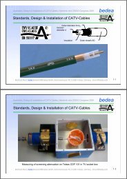
(angled)-Housing:<br />
Measuring of Transfer impedance and Screening attenuation of connecting hardware, in combination<br />
with the "tube in tube" procedure.<br />
generator<br />
tube<br />
<strong>de</strong>vice un<strong>de</strong>r<br />
test, DUT<br />
receiver<br />
Tube in tube<br />
connectingcable<br />
test head with<br />
screening cap<br />
(angled)-<br />
housing
e<strong>de</strong>a – Rosenberger<br />
Software Win<strong>CoMeT</strong><br />
Functions:<br />
Controlling of network analysers to measure<br />
• Transfer impedance acc. IEC 62153-4-3<br />
and EN 50289-1-6<br />
• Screening attenuation acc. IEC 62153-4-4<br />
and EN 50289-1-6<br />
• Transfer impedance, Co<strong>up</strong>ling attenuation<br />
& Screening attenuation acc. to<br />
IEC 62153-4-7, Tube in tube method<br />
• Co<strong>up</strong>ling attenuation at balanced cables<br />
(data cables) according to IEC 62153-4-9<br />
Description:<br />
• Intuitive operating surface<br />
• Ergonomic, effective user’s guidance<br />
• Operation by keyboard or mouse<br />
• Menu controlled<br />
• Input window with selecting windows<br />
• Comprehensive helps<br />
• Memorising of <strong>set</strong>tings and parameters<br />
Input window:<br />
Measuring diagram of screening attenuation<br />
Analysis, adaptation, monitoring, of the<br />
measurement resultsExtend of s<strong>up</strong>ply<br />
• Software (run-time-licence),<br />
• German or English manual<br />
Hardware requirements<br />
• PC Pentium 90<br />
• RAM min. 32 MB<br />
• Operating system: Windows 9x/NT/2000/XP<br />
• IEEE-Interface card:<br />
NI 488.2 from Version 2.10,<br />
It is possible to run the software without IEEE-<br />
Interface card for evaluation of measured datas,<br />
documentation e.t.a. Measurements can be<br />
achieved only via Interface card.<br />
• Network analyser Roh<strong>de</strong> & Schwarz ZVR or<br />
Hewlett Packard 8753 B/D/E, others on request<br />
• All printers<br />
Production of all components:<br />
Rosenberger Hochfrequenztechnik GmbH & Co.<br />
Postfach 1260, D - 84526 Tittmoning, Germany<br />
www.rosenberger.<strong>de</strong><br />
Sales and Service:<br />
be<strong>de</strong>a BERKENHOFF & DREBES GMBH<br />
Postfach 11 40 • D-35607 Aßlar, Germany<br />
phone: +49 6441 / 801-133 • fax: +49 6441 / 801-265<br />
e-mail: bmund@be<strong>de</strong>a.com<br />
www.be<strong>de</strong>a.com