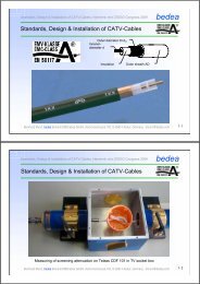
MEASUREMENTS OF THE SCREENING ... - Bmund.de
MEASUREMENTS OF THE SCREENING ... - Bmund.de
MEASUREMENTS OF THE SCREENING ... - Bmund.de

Create successful ePaper yourself
Turn your PDF publications into a flip-book with our unique Google optimized e-Paper software.
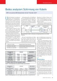
INTERNATIONAL WROCŁAW SYMPOSIUM AND EXHIBITION<br />
EMC 2002 ON ELECTROMAGNETIC COMPATIBILITY<br />
<strong>MEASUREMENTS</strong> <strong>OF</strong> <strong>THE</strong> <strong>SCREENING</strong> EFFECTIVENESS <strong>OF</strong><br />
CONNECTORS AND CABLE ASSEMBLIES<br />
Thomas Hähner*, Bernhard Mund**<br />
*Nexans France, 15 rue Lambin, 60120 Paillart, France, phone +33 3 44 80 67 21<br />
**Be<strong>de</strong>a, Herbornerstraße 100, 35614 Aßlar, Germany, phone +49 6441 801 133<br />
*thomas.haehner@nexans.com<br />
**bmund@be<strong>de</strong>a.com<br />
Abstract: This report <strong>de</strong>scribes a test method to<br />
<strong>de</strong>termine the screening effectiveness of connectors<br />
and cable assemblies. The shiel<strong>de</strong>d screening<br />
attenuation (long triaxial) test set-up according to<br />
IEC 61196-1 clause 12.6 is used and has been exten<strong>de</strong>d<br />
to take into account the particularities of<br />
connectors and cable assemblies. This method is<br />
now un<strong>de</strong>r discussion in the international working<br />
group IEC TC 46 WG5.<br />
Keywords: cable assembly, connector, screening<br />
effectiveness, triaxial set-up.<br />
1. INTRODUCTION<br />
Due to the increasing use of all kind of electric or<br />
electronic equipment, electromagnetic pollution increases.<br />
To reduce this electromagnetic pollution,<br />
all components of a system, especially the<br />
connecting cables (assemblies) shall be screened.<br />
It is obvious, that one needs standardised measuring<br />
procedures to compare the screening<br />
effectiveness of different screen <strong>de</strong>signs. The<br />
basic screening parameters are the transfer impedance<br />
Z T and the screening attenuation a S or<br />
coupling attenuation a C . One already has either the<br />
triaxial or the line injection method to obtain the<br />
transfer impedance Z T of cables, connectors and<br />
cable assemblies. However for the measurement<br />
of the screening a S or coupling a C attenuation of<br />
connectors and cable assemblies an easy and cost<br />
effective method is missing.<br />
Recently one has introduced the shiel<strong>de</strong>d screening<br />
attenuation (long triaxial) test method for the<br />
measurement of the screening or coupling attenuation<br />
of cables [1][2][3]. That method could also be<br />
used for the measurement of connectors and cable<br />
assemblies. In the following the principles are <strong>de</strong>scribed.<br />
2. PHYSICAL BASICS<br />
2.1 General coupling equation<br />
For the measurement of the coupling it is expedient<br />
to use the concept of operational attenuation with<br />
the square root of power waves, like in the <strong>de</strong>finition<br />
of scattering parameters [4][5]. The general<br />
coupling transfer function is then <strong>de</strong>fined as:<br />
T<br />
U<br />
Z<br />
P<br />
2n,<br />
f 2 2n,<br />
f<br />
n,<br />
f<br />
<br />
( 1 )<br />
U1<br />
Z1<br />
P0<br />
The electromagnetic influence between the sample<br />
un<strong>de</strong>r test and the surrounding is in principle the<br />
crosstalk between two lines and is caused by capacitive<br />
and magnetic coupling. At the near end the<br />
magnetic and capacitive coupling add where at the<br />
far end they subtract [5][6]. The coupling along the<br />
sample length is obtained by integrating the infinitesimal<br />
coupling distribution along the sample with<br />
the correct phase. The phase effect, when summing<br />
up the infinitesimal couplings along the line is<br />
expressed by the summing function S [5]. When<br />
the sample attenuation is neglected than S could<br />
be expressed by the following equation. Where 1,2<br />
are the phase velocities of the primary respectively<br />
secondary circuit and l the coupling length. The indices<br />
n and f <strong>de</strong>note the near respectively far end.<br />
<br />
<br />
1<br />
<br />
l<br />
sin <br />
<br />
2<br />
l 2<br />
S n , f lf <br />
exp<br />
j<br />
<br />
2<br />
21<br />
l<br />
21<br />
Z 2n<br />
Z 1n<br />
P<br />
0<br />
P 2 n<br />
U 2<br />
U 1<br />
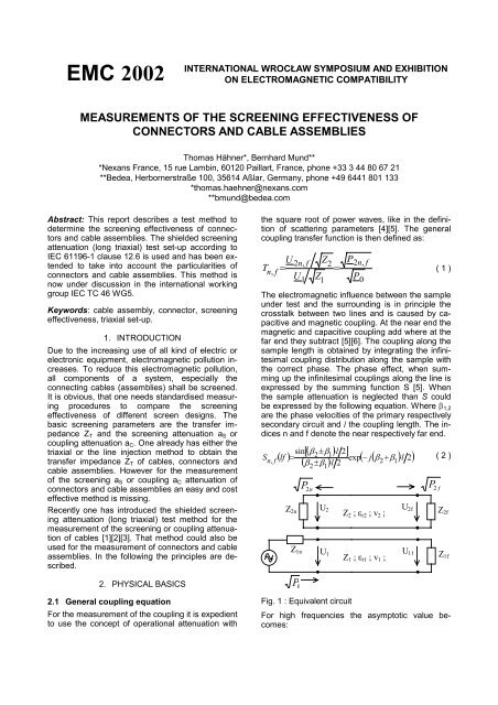
Fig. 1 : Equivalent circuit<br />
<br />
Z 2 ; r2 ; v 2 ;<br />
Z 1 ; r1 ; v 1 ;<br />
2<br />
U 2f<br />
U 1f<br />
P 2 f<br />
( 2 )<br />
Z 2f<br />
Z1f<br />
For high frequencies the asymptotic value becomes:
Sn<br />
f<br />
2<br />
<br />
( 1<br />
2<br />
) l<br />
( 3 )<br />
And for low frequencies the summing function becomes:<br />
For low frequencies, when S=1, the coupling transfer<br />
function corresponds to the frequency behaviour<br />
of the surface transfer impedance and capacitive<br />
coupling impedance. After a rise with 20 dB per<br />
<strong>de</strong>ca<strong>de</strong> the coupling transfer function shows different<br />
cut off frequencies f cn,f for the near and far end.<br />
Above these cut off frequencies the samples are<br />
consi<strong>de</strong>red as electrical long.<br />
S 1<br />
( 4 )<br />
n<br />
f<br />
S log scale<br />
T f<br />
Tn<br />
1<br />
S n<br />
S f<br />
(lf) cn<br />
(lf) cf<br />
log (lf)<br />
Fig. 2 : Summing function S<br />
The point of intersection between the asymptotic<br />
values for low and high frequencies is the so called<br />
cut-off frequency f c . This frequency gives the condition<br />
for electrical long sampels:<br />
f<br />
c ,<br />
f n<br />
l <br />
<br />
<br />
c<br />
( 5 )<br />
r1<br />
<br />
<br />
r2<br />
where r1,2 are the relative dielectric permittivity of<br />
the inner and the outer system and l is the cable<br />
length.<br />
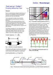
2.2 Coupling transfer function<br />
2.2.1 Homogenous screens<br />
The primary screening quantities of a screen are<br />
the surface transfer impedance Z T and the capacitive<br />
coupling impedance Z F or the effective transfer<br />
impedance Z TE . For homogeneous screens like for<br />
connectors or cables they can be assumed to be<br />
constant along the length. The integration could<br />
then be easily solved. The coupling between the<br />
sample and the surrounding could be expressed by<br />
the following coupling transfer function. For<br />
matched lines it is [4][5]:<br />
T<br />
s<br />
f n<br />
<br />
<br />
Z<br />
F<br />
Z<br />
T<br />
<br />
<br />
1<br />
Z Z<br />
1<br />
2<br />
l<br />
S<br />
2<br />
,<br />
( 6 )<br />
n<br />
f<br />
10 kHz 100 kHz 1 MHz 10 MHz fcn fcf 1 GHz 10<br />
GH<br />
Fig. 3 : Calculated coupling transfer function<br />
(l = 1 m; r1 = 2,3; r2 = 1; Z F =0)<br />
Below the cut off frequencies the surface transferimpedance<br />
Z T is the measure of the screening effectiveness.<br />
The value of the transferimpedance Z T<br />
increases with the sample length.<br />
Above the cut off frequencies in the range of wave<br />
propagation, respectively in the range where the<br />
samples are electrical long, the screening attenuation<br />
a S is the parameter for the screening effectiveness.<br />
The screening attenuation is a length in<strong>de</strong>pen<strong>de</strong>nt<br />
quantity.<br />
2.2.2 Cable assembly screens<br />
Cable assemblies are composed by the cable itself<br />
and a connector at each end. In addition to the<br />
coupling of the components itself also the coupling<br />
of the transition between cable and connector has<br />
to be taken into account. A good connector and a<br />
good cable screen doesn’t mean - without any precautions<br />
- a good assembly.<br />
Each part of it has a different coupling, thus one<br />
has to integrate in sections along the sample, i.e.<br />
one section for each component (connector A,<br />
transition, cable, transition, connector B). In a first<br />
approach the velocity in each section could be assumed<br />
to be equal. The coupling transfer function<br />
for matched lines is then expressed by:<br />
n Z<br />
<br />
F iZ<br />
i<br />
T i <br />
L L<br />
T<br />
<br />
<br />
<br />
1 1<br />
, , ( 1<br />
2 n<br />
e<br />
) i ( 1<br />
2<br />
e<br />
i<br />
k 1 1<br />
)<br />
1<br />
2<br />
i 1 <br />
2 Z1<br />
Z2<br />
<br />
<br />
2L n <br />
e C ZF , i ZT , i<br />
Tf<br />
<br />
1<br />
2 i1 <br />
2 Z1Z<br />
2<br />
where:<br />
e<br />
i<br />
1<br />
( 1<br />
2 ) L i<br />
k1<br />
<br />
<br />
1<br />
e<br />
<br />
( 7 )<br />
(<br />
1<br />
2 ) Li<br />
<br />
<br />
<br />
( 8 )
1,2 complex wave propagation constant of inner<br />
respectively outer circuit<br />
L c whole coupling length (sum of the segment<br />
lengths)<br />
L i length of segment i<br />
n number of segments (for cable assemblies 3)<br />
T n,f coupling transfer function at the near respectively<br />
far end<br />
Z 1,2 Characteristic impedance of inner respectively<br />
outer circuit<br />
Z F Capacitive coupling impedance<br />
Z T Surface transfer impedance<br />
2.2.3 Coupling in the triaxial set-up<br />
The above mentioned coupling transfer functions<br />
are valid if the primary and secondary circuit are<br />
matched. However in the triaxial set-up the secondary<br />
system (outer circuit) is mismatched (see also<br />
the following section). At the near end one has the<br />
short circuit between the sample screen. At the far<br />
end one has the mismatch between the impedance<br />
of the outer circuit and the receiver input impedance<br />
resulting in the reflection coefficient r 2,f . In<br />
that case the resulting coupling transfer function (at<br />
the receiver end) is obtained by:<br />
T<br />
<br />
<br />
1r<br />
*<br />
<br />
2L e<br />
C f<br />
Tf<br />
Tn<br />
<br />
2<br />
2 C<br />
1r<br />
e<br />
L<br />
( 9 )<br />
f<br />
<br />
2,<br />
2,<br />
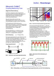
3. TRIAXIAL TEST SET-UP<br />
3.1 General<br />
The triaxial test set-up is one of the classical methods<br />
to measure the transferimpedance and has<br />
been recently exten<strong>de</strong>d for the measurement of the<br />
screening attenuation of cable screens [1][2]. The<br />
triaxial set-up is <strong>de</strong>scribed in IEC 61196-1 and EN<br />
50289-1-6, and consists of a tube of brass or aluminium<br />
with an inner diameter of about 40 mm.<br />
1 2 3 4 5<br />
L<br />
1 generator 4 termination load<br />
2 cable un<strong>de</strong>r test 5 measuring receiver<br />
3 measuring tube L coupling length<br />
Fig. 4 : triaxial set-up for the measurement of the<br />
screening attenuation a S and the transfer impedance<br />
Z T<br />
For the measurement of the transfer impedance<br />
(electrically short coupling length) the tube length is<br />
0,5 m to 1 m. For the measurement of the screening<br />
attenuation (electrically long coupling length)<br />
the measuring tube is exten<strong>de</strong>d to a length of 2m<br />
to 3m. (See also above theoretical explanation).<br />
In the outer circuit, at the near end the screen un<strong>de</strong>r<br />
test is short circuited with the measuring tube.<br />
The electrical waves, which are coupled over the<br />
whole cable length from the inner system into the<br />
outer system, are travelling in both directions, to<br />
the near and the far end. At the short circuited end<br />
they are totally reflected, so that at the measuring<br />
receiver the superposition of near and far end coupling<br />
can be measured as the disturbance voltage<br />
ratio U 2 /U 1 . The screening attenuation as a power<br />
ratio is then related to a standardised characteristic<br />
impedance of the outer system Z s =150.<br />
a<br />
s<br />
<br />
<br />
U<br />
20log<br />
U<br />
1<br />
max<br />
<br />
<br />
<br />
10log<br />
<br />
<br />
2<br />
2<br />
Z<br />
Z<br />
1<br />
s<br />
<br />
<br />
<br />
( 10 )<br />
where Z 1 is the characteristic impedance of the<br />
sample un<strong>de</strong>r test and Z s is 150 .<br />
3.2 Measurement of cable assemblies<br />
3.2.1 General<br />
When measuring cable assemblies in the triaxial<br />
test set-up one has the problem, that their lengths<br />
are differing wi<strong>de</strong>ly and are either shorter or longer<br />
than the commonly used measuring tube of 2 or<br />
3m. However the investigations of the above given<br />
coupling functions show, that:<br />
a) for assemblies longer than the measuring tube it<br />
is sufficient enough to measure just both accessible<br />
assembly ends.<br />
b) for assemblies shorter than the measuring tube<br />
one can extend the assembly by a well<br />
screened cable insi<strong>de</strong> a closed copper tube.<br />
The so called tube in tube method.<br />
3.2.2 Assembly longer than the measuring tube<br />
In screening attenuation measurements of cable<br />
assemblies it is evi<strong>de</strong>nt, that the result is characterised<br />
by the weakest part. Either the cable or the<br />
connector respectively the transition between cable<br />
and connector. Thus for cable assemblies, which<br />
are longer than the measuring tube it is sufficient<br />
enough to measure just both accessible ends (provi<strong>de</strong>d<br />
that the cable screen is homogenous). The<br />
following simulated graphs un<strong>de</strong>rline that evi<strong>de</strong>nce.<br />
The simulation parameters are:<br />
a) cable screen<br />
length:<br />
500 cm<br />
DC resistance: 13 m/m<br />
magnetic coupling: 0,04 mH/m<br />
capacitive coupling: 0,02 pF/m<br />
b) connector screen including transition from cable<br />
to connector<br />
length:<br />
5 cm<br />
DC resistance: 2 m/m<br />
magnetic coupling: 0,002 mH<br />
capacitive coupling: 0 pF/m<br />
c) outer circuit (secondary system)
impedance:<br />
150 <br />
dielectric permittivity: 1,1<br />
d) inner circuit (primary system)<br />
impedance:<br />
50 <br />
dielectric permittivity: 2,3<br />
tube, than one can extend the assembly by a well<br />
screened connecting cable insi<strong>de</strong> a closed copper<br />
tube. The so called tube in tube method (see also<br />
Fig. 7).<br />
The extension tube is than acting as a resonator.<br />
The same principle is also used for the measurement<br />
of connectors. Further <strong>de</strong>tails can be obtained<br />
from the following explanation of the measurement<br />
of connectors.<br />
3.3 Measurement of connectors<br />
Fig. 5 : simulation of a cable assembly (log scale)<br />
Fig. 6 : simulation of a cable assembly (lin scale)<br />
The blue line shows the result of the complete cable<br />
assembly, i.e. 500 cm cable and both connectors.<br />
The red line shows the result for just one part<br />
of the assembly, i.e. 195 cm of the cable and one<br />
connector. In the lower frequency range, where the<br />
samples are electrically short one gets a length <strong>de</strong>pen<strong>de</strong>nt<br />
result. However in the higher frequency<br />
range, where the samples are electrically long, one<br />
gets the same minimum value, i.e. the same<br />
screening attenuation of 47 dB.<br />
3.2.3 Assembly shorter than the measuring tube<br />
When the assembly is shorter than the measuring<br />
3.3.1 General<br />
Usual RF connectors have mechanical dimensions<br />
in the longitudinal axis in the range of 10mm to<br />
50mm. With equation (5), i.e. the <strong>de</strong>finition of electrical<br />
long elements, we get cut off frequencies of<br />
about 3 GHz or higher for standard RF-connectors.<br />
Above that frequency they are consi<strong>de</strong>red to be<br />
electrically long.<br />
The screening attenuation is by <strong>de</strong>finition only valid<br />
in the frequency range above the cut off frequency,<br />
where the elements are electrically long. Thus the<br />
screening attenuation of a RF connector itself can<br />
only be measured at frequencies above 3 GHz.<br />
However by extending the RF-connector by a RFtight<br />
closed metallic tube, one is building a cable<br />
assembly which is electrically long. Thus the cut off<br />
frequency respectively the lower frequency limit to<br />
measure the screening attenuation is exten<strong>de</strong>d towards<br />
lower frequencies. If one connects this extension<br />
tube directly to the connector un<strong>de</strong>r test,<br />
one is measuring the screening attenuation of the<br />
connector (and its mated adapter). If one connects<br />
the extension tube to the connecting cable close to<br />
the connector, one is measuring the screening attenuation<br />
of the combination of the connector (and<br />
its mated adapter) and the transition between cable<br />
and connector (see also Fig. 8).<br />
Note: Although the connector itself stays electrically<br />
short, the combination of the connector and the extension<br />
tube shows the behaviour (the screening<br />
attenuation) of the connector when connected to a<br />
well screened cable, which has a screening effectiveness<br />
better than the one of the connector (or<br />
the transition between cable and connector). See<br />
also the explanation in the following section.<br />
tube<br />
connector interface<br />
assembly un<strong>de</strong>r test<br />
connector un<strong>de</strong>r test<br />
mated adapter<br />
generator<br />
receiver<br />
generator<br />
receiver<br />
Fig. 7 :<br />
connecting cable<br />
extension tube<br />
screening cap<br />
triaxial set-up with extension tube for short<br />
cable assemblies<br />
extension tube<br />
connecting cable<br />
Fig. 8 :<br />
Measuring tube<br />
screening cap<br />
triaxial set-up with extension tube for<br />
connectors.
3.3.2 Measurement set-up<br />
For the measurement of RF connectors the triaxial<br />
set-up according to IEC 61196-1 has been exten<strong>de</strong>d<br />
by a RF-tight closed metallic tube (see Fig.<br />
8). The extension tube is either connected to the<br />
connector un<strong>de</strong>r test or to the screen of the connecting<br />
cable of the connector un<strong>de</strong>r test. At the far<br />
end the connector un<strong>de</strong>r test is connected to the<br />
screening cap of the triaxial test set-up via its<br />
mated adapter.<br />
The measurement of the screening attenuation itself<br />
is the same as the measurement of cable<br />
screens according to IEC 61196-1 Amendment 2<br />
clause 12.6.<br />
3.3.3 Measurement results and simulations<br />
In a first approach one has measured short cable<br />
pieces instead of a connector. The advantage is,<br />
that the results are not influenced by a mating<br />
adapter or the transition between cable and connector.<br />
The cable has been a coaxial cable with an<br />
impedance of 75, foam PE dielectric and a single<br />
braid screen (not optimised, i.e. un<strong>de</strong>r-brai<strong>de</strong>d).<br />
The simulations have been done with the equations<br />
(7), (8) and (9) where the number of sections is 2.<br />
The first section is the connecting cable with the<br />
RF-tight extension tube.<br />
Fig. 9 : simulation, log. frequency scale<br />
Fig. 10 : measurement, log. frequency scale<br />
Fig. 11 : simulation, lin. frequency scale<br />
Fig. 12 : measurement, lin. frequency scale<br />
Fig. 13 : simulation, log. frequency scale<br />
Fig. 14 : simulation, lin. frequency scale
Thus the transfer impedance and capacitive coupling<br />
impedance of that section is neglected. The<br />
second section is the cable un<strong>de</strong>r test with following<br />
parameter:<br />
DC resistance:<br />
8 m/m<br />
magnetic coupling: 0,6 mH/m<br />
capacitive coupling: 0,02 pF/m<br />
impedance:<br />
75 <br />
dielectric permittivity: 1,35<br />
The comparison of the simulation (Fig. 9, 11) with<br />
the measurement results (Fig. 10, 12) show a good<br />
correspon<strong>de</strong>nce. In the lower frequency range,<br />
when the samples are electrically short one gets<br />
the same results. However in the higher frequency<br />
range one can see the influence of the extension<br />
tube. The 10cm sample is electrically short over<br />
the whole frequency range, as the cut-off frequency<br />
is 5,9 GHz. Thus the coupled power is increasing<br />
with increasing frequency. However the quasi cable<br />
assembly composed of the connector and the extension<br />
tube is electrically long above 590 MHz,<br />
which results in a constant maximum coupled<br />
power. One characteristic of an electrically long object<br />
is also, that the maximum coupled power is in<strong>de</strong>pen<strong>de</strong>nt<br />
of the sample length (see clause<br />
“General coupling equation”). This is un<strong>de</strong>rlined in<br />
figure 13 and 14, where the simulated results of a<br />
4cm sample in a 1m respectively 2m tube, i.e. with<br />
a 96cm respectively 196cm extension tube, are<br />
shown. The envelope of both curves is i<strong>de</strong>ntical.<br />
4. CONCLUSION<br />
Customers and users of RF cables, cable assemblies<br />
and connectors ask more often for screening<br />
effectiveness values in <strong>de</strong>cibels (dB) instead of<br />
transferimpedance values in m respectively<br />
m/m. The explained tube in tube method reply to<br />
that need since it offers a simple and reliable<br />
method to measure the screening attenuation in dB<br />
on connectors and cable assemblies. That method<br />
is an extension of the shiel<strong>de</strong>d screening attenuation<br />
(long triaxial) test set-up according to IEC<br />
61196-1 clause 12.6<br />
The comparison of the measured and the calculated<br />
curves show good concordance.<br />
The advantages of the tube in tube method for<br />
connectors and assemblies are the same as for the<br />
measurement of the screening attenuation of cable<br />
screens in the tube:<br />
simple and easy test set-up<br />
insensitive against electro magnetic disturbances<br />
from outsi<strong>de</strong><br />
high dynamic range > 130 dB<br />
good reproducibility<br />
A future investigation is the measurement of the<br />
screening attenuation of connectors for balanced<br />
cables and for multipin connectors.<br />
5. REFERENCES<br />
[1] O. Breitenbach, T. Hähner, B. Mund, "Screening<br />
of cables in the MHz to GHz frequency range<br />
exten<strong>de</strong>d application of a simple measuring<br />
method", Colloquium on screening effectiveness<br />
measurements, Savoy Place London, 6<br />
May 1998, Reference No:1998/452<br />
[2] IEC 61196-1 Amendment 2 clause 12.6<br />
[3] T. Hähner, B. Mund, "test methods for screening<br />
and balance of communication cables", 13 th<br />
international Zurich EMC Symposium, February<br />
16-18 1999<br />
[4] L. Halme, R. Kytönen, "Background and introduction<br />
to EM screening (shielding) behaviours<br />
and measurements of coaxial and symmetrical<br />
cables, cable assemblies and connectors", Colloquium<br />
on screening effectiveness measurements,<br />
Savoy Place London, 6 May 1998, Reference<br />
No:1998/452.<br />
[5] Halme, L./Szentkuti, B, "The background for<br />
electromagnetic screening measurements of cylindrical<br />
screens", Tech. Rep. PTT(1988) Nr. 3<br />
[6] W. Klein, "Die Theorie <strong>de</strong>s Nebensprechens auf<br />
Leitungen", (German), Springer Verlag 1955<br />
BIOGRAPHICAL NOTES<br />
Thomas Hähner was born 1965<br />
in Germany. He received his<br />
Dipl.-Ing. <strong>de</strong>gree for information<br />
and communication techniques<br />
from the Georg-Simon-Ohm<br />
Fachhochschule Nürnberg in<br />
1989. He joined Nexans Germany<br />
in 1990, where he was responsible<br />
for the <strong>de</strong>velopment<br />
and <strong>de</strong>sign of communication cables and the RFlaboratory.<br />
In 2000 he received his Dipl. Wirt.-Ing.<br />
<strong>de</strong>gree from Technische Fachhochschule Wildau<br />
and moved to the mother company in France,<br />
where he is now responsible for the technical support.<br />
Thomas is a member of several national and<br />
international standardisation committees, e.g. in<br />
IEC TC46/WG5, screening effectiveness.<br />
Bernhard Mund was born 1953 in<br />
Germany. He received his Dipl.-<br />
Ing. <strong>de</strong>gree for communicationand<br />
microprocessor-techniques<br />
from the Fachhochschule<br />
Gießen-Friedberg in 1984. He<br />
joined the be<strong>de</strong>a Berkenhoff &<br />
Drebes GmbH in 1985, where he<br />
is responsible for the <strong>de</strong>velopment and <strong>de</strong>sign<br />
communication cables and the RF-laboratory.<br />
Bernhard is a member of several national and international<br />
standardisation committees, e.g. in<br />
IEC TC46/WG5, screening effectiveness.