SSP 303 V10 TDI Engi.. - Free
SSP 303 V10 TDI Engi.. - Free
SSP 303 V10 TDI Engi.. - Free

Create successful ePaper yourself
Turn your PDF publications into a flip-book with our unique Google optimized e-Paper software.
Service.<br />
Self-Study Programme <strong>303</strong><br />
The <strong>V10</strong>-<strong>TDI</strong> engine<br />
with pump-jet fuel injection system<br />
Design and function
... Easy to recognise, the beauty of the classical lines,<br />
the calm but predominantly powerful charisma<br />
of intelligent and sensible engine activity, simple and elegant –<br />
in short, ladies and gentlemen,<br />
you can see here the world’s top performer!<br />
A milestone...<br />
... in statuary! ... in engine development!<br />
<strong>303</strong>_U2<br />
With the <strong>V10</strong>-<strong>TDI</strong> engine, Volkswagen once again sets new standards in diesel technology.<br />
Due to a multitude of innovative techniques, the highest demands in terms of performance, torque<br />
and emissions made of a diesel motor are fulfilled for the luxury vehicle class.<br />
The <strong>V10</strong>-<strong>TDI</strong> engine crowns 25 years of diesel engine development at Volkswagen.<br />
It is the most powerful series passenger-vehicle diesel engine in the world.<br />
NEWCaution<br />
Note<br />
2<br />
The Self-Study Programme describes the<br />
design and function of new developments!<br />
The contents are not updated.<br />
Please always refer to the relevant service<br />
literature for up-to-date inspection, adjustment<br />
and repair instructions.
At a glance<br />
Introduction . . . . . . . . . . . . . . . . . . . . . . . . . . . . . . . . . . . . . . . . . . 4<br />
<strong>Engi</strong>ne mechanics . . . . . . . . . . . . . . . . . . . . . . . . . . . . . . . . . . . . . 6<br />
Oil circulation . . . . . . . . . . . . . . . . . . . . . . . . . . . . . . . . . . . . . . . . . . .20<br />
Coolant circulation system . . . . . . . . . . . . . . . . . . . . . . . . . . . . . . . . .26<br />
Fuel system. . . . . . . . . . . . . . . . . . . . . . . . . . . . . . . . . . . . . . . . . . . . . . 32<br />
System overview . . . . . . . . . . . . . . . . . . . . . . . . . . . . . . . . . . . . . 40<br />
Service . . . . . . . . . . . . . . . . . . . . . . . . . . . . . . . . . . . . . . . . . . . . . 42<br />
Check your knowledge . . . . . . . . . . . . . . . . . . . . . . . . . . . . . . . . 46<br />
3
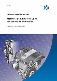
Introduction<br />
The <strong>V10</strong>-<strong>TDI</strong> engine<br />
The <strong>V10</strong>-<strong>TDI</strong> engine is a newly developed<br />
diesel engine in which innovative light-weight<br />
construction and enormous power are united<br />
within compact dimensions.<br />
It has a cylinder block made of aluminium, where<br />
the two rows of cylinders are arranged at an<br />
angle of 90 o to one another.<br />
The control and ancillary unit is driven by<br />
gearwheels The tried-and-tested pump-jet fuel<br />
injection system ensures a high performance yield<br />
at low exhaust emissions.<br />
The <strong>V10</strong>-<strong>TDI</strong> engine is used as a high-performance<br />
engine in the Volkswagen Touareg and Phaeton.<br />
<strong>303</strong>_001<br />
<strong>Engi</strong>ne mechanics technical features<br />
– Cylinder block made of aluminium with an<br />
end bracket made of cast-iron<br />
– Joining of cylinder head and cylinder block<br />
via tie-rod screw connection<br />
– Contol and ancillary unit driven by<br />
gearwheels<br />
– Balancer shaft for reducing vibrations<br />
<strong>Engi</strong>ne management technical features<br />
– Two motor controllers<br />
– Charged by two adjustable turbochargers<br />
– Exhaust gas recirculation effected with<br />
pneumatically controlled exhaust gas<br />
recirculation valves with electrically-operated<br />
intake manifold flaps<br />
– Lambda probes for controlling exhaust gas<br />
recirculation<br />
A detailed description of the engine management system for the <strong>V10</strong>-<strong>TDI</strong> engine can be<br />
found in Self-Study Programme No. 304 ”Electronic Diesel Control EDC 16”.<br />
4
Technical data<br />
<strong>Engi</strong>ne code<br />
AYH<br />
(in the Touareg)<br />
Construction<br />
V engine, 90 o V-angle<br />
Displacement 4921 cm 3<br />
AJS<br />
(in the Phaeton)<br />
Bore<br />
81 mm<br />
Stroke<br />
95.5 mm<br />
Valves per cylinder 2<br />
Compression ratio 18 : 1<br />
Max. output<br />
230 kW at 4000 rpm<br />
Max. torque<br />
750 Nm at 2000 rpm<br />
<strong>Engi</strong>ne management Bosch EDC 16<br />
Fuel<br />
Diesel at least 49 CZ or biodiesel<br />
Exhaust treatment<br />
Exhaust gas recirculation and oxidation catalytic converter<br />
Ignition sequence 1 - 6 - 5 - 10 - 2 - 7 - 3 - 8 - 4 - 9<br />
Exhaust emission standard EU 3<br />
Power/torque diagram<br />
(kW)<br />
Performance (kW)<br />
260<br />
240<br />
220<br />
200<br />
180<br />
160<br />
140<br />
120<br />
100<br />
80<br />
800<br />
700<br />
600<br />
500<br />
400<br />
300<br />
200<br />
(Nm)<br />
Torque (Nm)<br />
The <strong>V10</strong>-<strong>TDI</strong> engine develops a maximum<br />
torque of 750 Nm at a speed as low as 2000 rpm.<br />
The nominal output of 230 kW is achieved at<br />
4000 rpm.<br />
60<br />
40<br />
20<br />
0 500 1000<br />
1500 2000 2500 3000 3500 4000 4500<br />
Speed (rpm)<br />
(1/min)<br />
<strong>303</strong>_002<br />
5
<strong>Engi</strong>ne mechanics<br />
Cylinder block<br />
The cylinder block consists of the top portion<br />
of the cylinder block and the end bracket.<br />
The top portion of the cylinder block is<br />
manufactured from an aluminium alloy; this is<br />
a significant factor in weight reduction.<br />
The cylinder rows are positioned at a 90 o angle<br />
to one other, permitting a compact design for the<br />
engine as a whole.<br />
Top portion of cylinder block<br />
End bracket<br />
<strong>303</strong>_031<br />
Cylinder walls with plasma-sprayed running<br />
film<br />
For the first time for diesel engines, a plasmasprayed<br />
running film is applied to the cylinder<br />
walls. As a result, the use of cylinder liners in the<br />
aluminium cylinder block is no longer necessary.<br />
This reduces the weight of the engine and<br />
permits compact dimensions due to a short<br />
distance between the cylinder bores.<br />
Plasma jet<br />
Plasma burner<br />
Cylinder wall<br />
<strong>303</strong>_069<br />
Detailled information regarding the plasma coating principle can be found in Self-Study<br />
Programme No. 252 ”The 1.4l/77 kW <strong>Engi</strong>ne with Direct Fuel Injection in the Lupo FSI”.<br />
6
End bracket<br />
The two-part end bracket is manufactured from high-tensile cast-iron.<br />
The upper and lower portions of the end bracket are attached by a press fit; in addition, they are<br />
screwed together. This provides the crankshaft bearing with the required sturdiness, so that the high<br />
combustion forces can be safely absorbed in the end bracket area.<br />
End bracket,<br />
upper portion<br />
End bracket,<br />
lower portion<br />
End bracket,<br />
upper portion<br />
End bracket,<br />
lower portion<br />
<strong>303</strong>_077<br />
Press fit<br />
<strong>303</strong>_087<br />
Thrust bearings for the balancer shaft<br />
Bolted connection<br />
The bolted connection of the cylinder<br />
block with the upper portion of the end<br />
bracket must not be loosened;<br />
otherwise, the cylinder block could<br />
deform. Please observe the instructions<br />
in the repair guidelines.<br />
<strong>303</strong>_022<br />
7
<strong>Engi</strong>ne mechanics<br />
Cylinder head<br />
The <strong>V10</strong>-<strong>TDI</strong> engine has two aluminium-alloy<br />
cylinder heads. The inlet and outlet channels are<br />
arranged according to the crossflow principle.<br />
The inlet and outlet channels are located on the<br />
side opposite of the cylinder head. This<br />
arrangement provides good gas exchange and<br />
thus good cylinder filling. The inlet channels are<br />
located in the V space of the engine, while the<br />
outlet channels are on the engine exterior.<br />
Tie rod principle<br />
In order to prevent tension in the cylinder block,<br />
the cylinder heads, the cylinder block and the<br />
end bracket are screwed to each other using tie<br />
rods.<br />
Inlet channel<br />
Outlet channel<br />
<strong>303</strong>_025<br />
Tie rod<br />
Cylinder head<br />
Cylinder block<br />
End bracket,<br />
upper portion<br />
Bedding of<br />
balancer shaft<br />
End bracket,<br />
lower portion<br />
<strong>303</strong>_049<br />
8
Crankshaft<br />
The crankshaft of the <strong>V10</strong>-<strong>TDI</strong> engine is made of<br />
tempering steel. It is forged from one part. The<br />
drive wheel for the geared drive, the sender<br />
wheel for the engine speed sender and screwedon<br />
counterweights are located on the crankshaft.<br />
Drive wheel for geared drive<br />
<strong>Engi</strong>ne speed sender wheel<br />
<strong>303</strong>_023<br />
Split pin displacement<br />
All the cylinders of a 4-stroke engine ignite within<br />
a crankshaft angle of 720 o .<br />
In order to attain uniform ignition, the ignition<br />
angle for a 10-cylinder engine must be 72 o .<br />
720 o crankshaft angle<br />
10 cylinders<br />
= 72 o ignition angle<br />
A 10-cylinder V-engine must therefore have a<br />
V-angle of 72 o .<br />
Since the <strong>V10</strong>-<strong>TDI</strong> engine has a V-angle of 90 o ,<br />
the split pin must be displaced by 18 o in order to<br />
attain uniform ignition.<br />
<strong>303</strong>_107<br />
90 o V-angle - 72 o ignition angle = 18 o split pin displacement<br />
9
<strong>Engi</strong>ne mechanics<br />
Piston and connecting rods<br />
In order keep the demands on the piston and<br />
connecting rods low at the high combustion<br />
pressures, the piston pin bosses and the<br />
connecting rod boss have a trapezoidal shape.<br />
This distributes the combustion forces over a<br />
broader area. The piston pin bosses are also<br />
strengthened by brass bushes.<br />
Cooling channel<br />
A cooling channel is infused into the piston to<br />
cool the piston ring zone. Oil is injected into this<br />
cooling channel from the oil-spraying jets as<br />
soon as the piston is located in the bottom dead<br />
centre.<br />
Brass bush<br />
<strong>303</strong>_097<br />
Connecting rod<br />
The connecting rod and the connecting rod lid<br />
are separated diagonally; they are separated<br />
by the crack procedure.<br />
Brass bush<br />
Displacement of the piston pin axis<br />
The piston pin axis is decentrally arranged in<br />
order to prevent noise from the tilting of the<br />
piston in the top dead centre.<br />
Each time that the connecting rod is in a sloping<br />
position, lateral piston forces occur which<br />
alternatingly press the piston against the cylinder<br />
walls.<br />
The lateral piston force changes direction in the<br />
top dead centre. The piston is tilted to the<br />
opposite cylinder wall there, thus resulting in<br />
noise.<br />
To prevent this, the piston pin axis is decentrally<br />
arranged.<br />
Due to the decentral arrangement of the piston<br />
pin axis, the piston changes sides before it<br />
reaches the top dead centre and then supports<br />
itself on the opposite cylinder wall.<br />
<strong>303</strong>_098<br />
Top dead centre<br />
<strong>303</strong>_099<br />
10
Mass balancing<br />
In order to attain low-vibration running of the<br />
engine, the moments of inertia must be<br />
balanced.<br />
The counterweights are made of a tungsten alloy.<br />
As tungsten has a high density, the weights can<br />
have small sizes, which saves space.<br />
For this, 6 counterweights are attached to the<br />
chrankshaft. In addition, a counter-rotating<br />
balancing shaft and a weight located in the drive<br />
wheel of the balancing shaft eliminate the<br />
moments of inertia. The balancing shaft is driven<br />
by the chrankshaft; at the same time, it serves as<br />
a driveshaft for the oil pump.<br />
Counterweight<br />
Crankshaft<br />
Vibration damper<br />
Silicone oil<br />
Sender wheel for<br />
engine speed sender<br />
Counterweight<br />
Balancing shaft<br />
Counterweight<br />
<strong>303</strong>_024<br />
Drive wheel<br />
for oil pump<br />
<strong>303</strong>_008<br />
Vibration damper<br />
The vibration damper reduces the rotational<br />
vibrations of the crankshaft. It is filled with a<br />
silicone oil.<br />
The rotational vibrations of the crankshaft that<br />
occur are eliminated by the shear forces of the<br />
silicone oil.<br />
11
<strong>Engi</strong>ne mechanics<br />
Overall view of the geared drive<br />
with auxiliary components<br />
The geared drive is located on the flywheel side.<br />
The camshafts as well as the auxiliary<br />
components are driven by the crankshaft by helic<br />
gear wheels.<br />
The advantage of gear wheels over a toothed<br />
belt is that larger forces can be transferred while<br />
the size remains the same. In addition gear<br />
wheels have no longitudinal expansion.<br />
Coolant pump<br />
The geared drive is maintenance-free.<br />
Drive wheel for camshaft<br />
Air-conditioning system compressor<br />
Coupling with Hardy discs<br />
Travelling direction<br />
Pump for power steering<br />
12
Alternator<br />
Drive wheel for camshaft<br />
Belt drive module<br />
Crankshaft<br />
<strong>303</strong>_016<br />
13
<strong>Engi</strong>ne mechanics<br />
Geared drive assembly<br />
Drive wheel – camshaft<br />
Cylinder bank I<br />
Drive wheel – alternator<br />
Compensation wheel<br />
Drive wheel for<br />
coolant pump<br />
Drive wheel – camshaft<br />
Cylinder bank II<br />
Crankshaft<br />
<strong>303</strong>_003<br />
Drive wheel – pump for power<br />
steering and air-conditioning system<br />
compressor<br />
Bolted connection with bearing tunnel<br />
Drive wheel – oil pump/balancing shaft<br />
14
Belt drive module<br />
The belt drive module is a component in which<br />
helic gear wheels are positioned between two<br />
carrier plates.<br />
To ensure that all components of the belt drive<br />
module expand uniformly when exposed to heat<br />
and, as a result, to ensure that the face play is<br />
the same in all operating states, the carrier<br />
plates of the belt drive module are manufactured<br />
from tempered cast-iron.<br />
The belt drive module is connected by three<br />
screws to the bearing tunnel, which is also<br />
manufactured from cast-iron.<br />
The gearwheels are made of steel. They have a<br />
helix angle of 15 o ; as a result, two tooth pairs are<br />
always meshing. In comparison to spur-toothed<br />
gearwheels, larger forces can be transferred,<br />
thus providing a high smoothness of running.<br />
Oil supply line<br />
Carrier plate<br />
Carrier plate<br />
<strong>303</strong>_102<br />
Carrier plate<br />
Carrier plate<br />
<strong>303</strong>_004<br />
15
<strong>Engi</strong>ne mechanics<br />
Shackle joint<br />
The drive wheels of the camshafts are connected<br />
to the geared drive by a shackle joint.<br />
The camshafts are located in the aluminium<br />
cylinder head. The carrier plates of the belt drive<br />
module are made of cast iron.<br />
As aluminium expands further when exposed to<br />
heat than does cast iron, the face play of the<br />
gearwheels must be compensated. For this<br />
purpose, a compensation wheel is positioned in<br />
a shackle joint between the camshaft wheel and<br />
the drive wheel of the belt drive module.<br />
<strong>303</strong>_045<br />
Balance piston<br />
Camshaft<br />
gearwheel<br />
Cylinder head<br />
<strong>303</strong>_113<br />
Shackle joint<br />
Camshaft<br />
gearwheel<br />
Compensation<br />
wheel<br />
Balance piston<br />
Drive wheel<br />
Shackle<br />
<strong>303</strong>_007<br />
16
How it works<br />
When subjected to heat, the axle spacing of the<br />
camshaft to the belt drive module changes.<br />
The compensation wheel in the shackle joint<br />
follows the joint movement; the face play<br />
between the wheels within the shackle joint<br />
remains equal.<br />
Setting for ”Cold engine”<br />
Setting for ”Warm engine”<br />
Compensation<br />
wheel<br />
Camshaft gearwheel<br />
Shackles<br />
Belt drive<br />
module<br />
Drive wheel<br />
<strong>303</strong>_017a<br />
<strong>303</strong>_017b<br />
Balance piston<br />
The shackles of the shackle joint are tensioned by<br />
a balance piston. The piston consists of a sleeve<br />
in which several spring washers are arranged<br />
behind one another and are axially tensioned.<br />
Balance piston<br />
<strong>303</strong>_037<br />
The balance piston is screwed into the cylinder<br />
head; using a full floating axle, it tensions the<br />
two shackle joints. This prevents ”dangling<br />
movements” of the shackle joint.<br />
Cylinder head<br />
Sleeve<br />
Full floating axle<br />
Compensation wheel<br />
<strong>303</strong>_083<br />
Spring washers<br />
Balance piston<br />
17
<strong>Engi</strong>ne mechanics<br />
Alternator<br />
The alternator is arranged in a space-saving<br />
manner in the V-space of the engine.<br />
It is driven by a geared drive via a transmission<br />
shaft and a Hardy disc of the geared drive. Due<br />
to the transmission shaft, the alternator speed<br />
increases by a factor of 3.6 compared to the<br />
engine speed.<br />
This provides an increased alternator<br />
performance that can cover high power<br />
demands of the vehicle electrical system even<br />
when idling.<br />
<strong>303</strong>_046<br />
The alternator is liquid-cooled.<br />
Coolant connection<br />
Alternator<br />
Power flow<br />
Transmission shaft<br />
Hardy disc<br />
<strong>303</strong>_101<br />
Crankshaft<br />
Geared drive<br />
<strong>303</strong>_095<br />
18
Power steering pump/airconditioning<br />
system compressor<br />
The power steering pump and the airconditioning<br />
system compressor are arranged in<br />
a row on the engine block. The power steering<br />
pump is driven directly by the geared drive.<br />
The air-conditioning system compressor is driven<br />
by the shared drive axis and two Hardy discs<br />
that are arranged in a row.<br />
The overload protection of the air-conditioning<br />
system compressor is implemented by a shaped<br />
rubber element.<br />
<strong>303</strong>_048<br />
Further information regarding the<br />
externally controlled air-conditioning<br />
system compressor can be found in<br />
Self-Study Programme No. 301 ”The<br />
Phaeton – Heating/Air-Conditioning<br />
System”<br />
Power steering pump<br />
Air-conditioning<br />
system compressor<br />
<strong>303</strong>_072<br />
The Hardy disc consists of a rubber body with<br />
integrated steel sleeves. It has the advantage<br />
that, due to its material elasticity, it permits small<br />
bending angles of the rotary axles and<br />
compensates for small changes in length<br />
between the connecting flanges. In addition, it<br />
has a vibration-dampening effect on torque<br />
fluctuations.<br />
Hardy discs<br />
<strong>303</strong>_096<br />
19
<strong>Engi</strong>ne mechanics<br />
Oil circulation<br />
Oil return baffle<br />
Oil return baffle<br />
Oil cooler<br />
Short-circuit valve<br />
Oil filter<br />
Oil-pressure switch<br />
Oil return baffle<br />
Vacuum pump<br />
Piston with<br />
cooling channel<br />
Exhaust<br />
turbocharger<br />
Oil-spraying jets<br />
(piston cooling)<br />
Oil separator<br />
Oil supply of the belt<br />
drive module<br />
Oil pump<br />
<strong>303</strong>_053<br />
Oil – without pressure<br />
Oil – with pressure<br />
Aspiration hole<br />
Oil pressure control valves<br />
The oil pressure control valves control the oil<br />
pressure of the engine. They open as soon as the<br />
oil pressure reaches the maximum permitted<br />
value.<br />
The oil return baffles prevent oil from flowing<br />
back out of the cylinder head and the oil filter<br />
housing into the oil pan when the engine is at a<br />
standstill.<br />
The short-circuit valve opens when the oil filter<br />
is occluded, thus ensuring the oil supply to the<br />
engine.<br />
20
Oil supply in belt drive module<br />
Main channel in<br />
cylinder head<br />
Main channel in<br />
cylinder head<br />
Cylinder head<br />
Oil line<br />
Oil line<br />
Oil channel in<br />
belt drive module<br />
Oil supply from<br />
cylinder block<br />
Belt drive module<br />
<strong>303</strong>_054<br />
Oil filter module<br />
The oil filter module is located in a space-saving<br />
manner in the V-space of the engine. The oil<br />
filters, the oil filler neck and the oil cooler are<br />
integrated in the oil filter module.<br />
Oil filter<br />
module<br />
Oil filler neck<br />
<strong>303</strong>_027<br />
Oil filter housing<br />
Oil cooler<br />
<strong>303</strong>_028<br />
21
<strong>Engi</strong>ne mechanics<br />
Oil pump<br />
The oil pump is located on the engine face in the<br />
oil sump of the oil pan. It has four pairs of<br />
toothed wheels, working according to the<br />
duocentric principle. Two of these are oil<br />
pressure pumps that generate the oil pressure<br />
that is required for the oil circulation.<br />
The other two are oil scavenge pumps that<br />
suction the oil out of the areas of the exhaust<br />
turbocharger oil returns, ensuring that there is a<br />
sufficient amount of oil in the oil filler neck in<br />
every operating state.<br />
The oil pump is driven by the geared drive via<br />
the balancer shaft.<br />
Oil pan, upper portion<br />
Oil return pipe<br />
Oil pressure pump<br />
Oil scavenge pump<br />
Lines of the<br />
oil scavenge pumps<br />
Oil pressure line to engine<br />
Oil separator<br />
<strong>303</strong>_093<br />
Suction lines of<br />
oil scavenge pumps<br />
Rotors of<br />
oil pressure pumps<br />
Oil separator<br />
Driving toothed<br />
wheel<br />
Rotors of<br />
oil scavenge pumps<br />
<strong>303</strong>_100<br />
22