ssp 250_engine manag..
ssp 250_engine manag..
ssp 250_engine manag..
- No tags were found...

You also want an ePaper? Increase the reach of your titles
YUMPU automatically turns print PDFs into web optimized ePapers that Google loves.
Table of contentsIntroduction . . . . . . . . . . . . . . . . . . . . . . . . . . . . . . . . . . .4System overview . . . . . . . . . . . . . . . . . . . . . . . . . . . . . . 8Subsystems . . . . . . . . . . . . . . . . . . . . . . . . . . . . . . . . . . 12Function diagram . . . . . . . . . . . . . . . . . . . . . . . . . . . . .52Service . . . . . . . . . . . . . . . . . . . . . . . . . . . . . . . . . . . . . .58Test your knowledge . . . . . . . . . . . . . . . . . . . . . . . . . 623
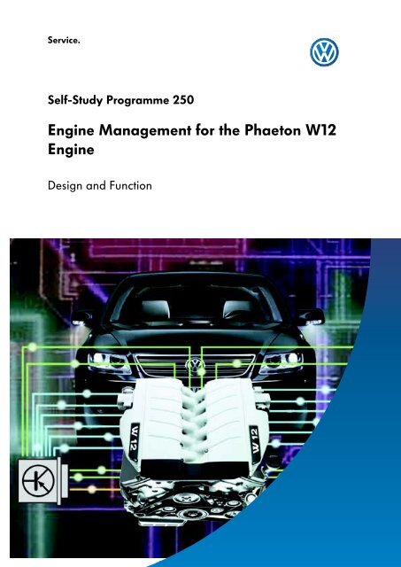
IntroductionThe Motronic ME7.1.1S<strong>250</strong>_225The Motronic ME7.1.1 controls the W12 <strong>engine</strong> bymeans of two <strong>engine</strong> control units.The <strong>engine</strong> <strong>manag</strong>ement system carries out thefollowing tasks:Both <strong>engine</strong> control units are located in theplenum chamber on the right under the coolantexpansion tank.- creates the optimum mixture for alloperating conditions- reduces fuel consumption- controls combustion- checks and controls emission values4
<strong>250</strong>_033Engine control unit 1 J623Engine control unit 2 J624<strong>250</strong>_009 <strong>250</strong>_008Terminal 15 Terminal 31As both control units are completely identicaland the <strong>engine</strong> control is fundamentally bankspecific,each control unit must be assigned toone of the cylinder banks. A Pin code is used toidentify <strong>engine</strong> control unit 1 J623 for cylinderbank I, and <strong>engine</strong> control unit 2 J624 forcylinder bank II.Pin 49 for <strong>engine</strong> control unit 1 is linked toTerminal 15 and Pin 49 for <strong>engine</strong> control unit 2 islinked with Terminal 31. The wiring harnesses arecolour-marked to distinguish them.Engine control unit 1 is also referred to as the "Master“ and <strong>engine</strong> control unit 2 as the"Slave“.5
IntroductionBoth <strong>engine</strong> control units <strong>manag</strong>e each bank separately to ensure that the following functions runsmoothly:- injection control- ignition control (ignition system with single spark ignition coils)- idling speed control- stereo lambda control of emission values- fuel tank breather system- electronic pow er control- cruise control system (CCS)- secondary air system- knock control- continually variable inlet and exhaust camshaft timing- <strong>engine</strong> mounting control- coolant temperature control- self-diagnosisThe following subfunctions are assumed only by <strong>engine</strong> control unit 1:incoming sensor signals:- from the coolant temperature sender- from the accelerator position sender- from the brake light switch- from the brake pedal switch- from the CCS switch- from the kick-down switchactivated actuators:- the current supply relay- the fuel pumps- the continued coolant circulation pump- the mapped-controlled <strong>engine</strong> coolingthermostat- the electro-hydraulic <strong>engine</strong> mountingsolenoid valve- the radiator fanThe input signals are processed by <strong>engine</strong> control unit 1 and transmitted to <strong>engine</strong> control unit 2 via theinternal CAN databus.There is only one G28 <strong>engine</strong> speed sender in the system. It transmits the <strong>engine</strong> speed signalto both <strong>engine</strong> control unit 1 and <strong>engine</strong> control unit 2.6
Engine control units in the CAN databus driveEngine control units 1 and 2 communicate withthe control units of other vehicle systems.Data is exchanged over the Drive Train CANdatabus. It connects the individual control unitsto an overall system.ImmobiliserEnginecontrol unit 1ABScontrol unitSteering anglesensorControl unit in thedash panel insertKessyInternal CAN databusCAN-LowCAN-HighEnginecontrol unit 2Gearboxcontrol unitAirbagcontrol unitAir conditionercontrol unitOnboard powersupply controlunitSteering columnmoduleS<strong>250</strong>_104The internal CAN databus has been added for<strong>engine</strong> <strong>manag</strong>ement in the W12 <strong>engine</strong> due tothe two-control unit concept.The internal CAN databus only exchangesinformation between the two <strong>engine</strong> controlunits.Kessy = entry and start authorisation relay J 518(Kessy = Keyless Entry)7
System controlEngine control unit 1SensorsG70 Air mass meterG42 Intake air temperature senderG28 Engine speed senderG62 Coolant temperature senderG83 Coolant temperature senderradiator outletG39 Lambda probeCANG108 Lambda probe IIG130 Lambda probe after catalystEngine control unit 1J623G131 Lambda probe II after catalystG40 Hall senderG300Hall sender 3G61 Knock sensor IG66 Knock sensor IIJ338 Throttle valve control unitG187 Throttle valve drive angle sender -1-G188 Throttle valve drive angle sender -2-Accelerator pedal module withG79 Accelerator pedal position senderG185 Accelerator pedal position sender -2-DiagnosisconnectionInternal CAN databusF8Kick-down switchE45 CCS switchE227 CCS buttonEngine control unit 2J624FF47Brake light switchCCS brake pedal switch8S<strong>250</strong>_003
ActuatorsJ17G6Fuel pump relayFuel pump (pre-supply pump)J49 Fuel pump relayG23 Fuel pumpJ338 Throttle valve control unitG186 Throttle valve driveN30 Injector, cylinder 1, N31 Injector, cylinder 2N32 Injector, cylinder 3, N33 Injector, cylinder 4N83 Injector, cylinder 5, N84 Injector, cylinder 6N70 Ignition coil 1 with output stage, N127 Ignition coil 2N291 Ignition coil 3 with output stage, N292 Ignition coil 4 outputstageN323 Ignition coil 5 output stage, N324 Ignition coil 6 output stageN205 Inlet camshaft timing adjustment valve -1-N318 Exhaust camshaft timing adjustment valve -1-N80 Activated charcoal filter system solenoid valve 1N112Secondary air inlet valveV101J299Secondary air pump motorSecondary air pump relayJ271 Motronic current supply relayJ670 Motronic current supply relay -2-J235V51Coolant pump relayContinued coolant circulation pumpF265Mapped-controlled <strong>engine</strong> cooling thermostatN145 Electro-hydraulic <strong>engine</strong> mounting solenoid valve, rightV7 Radiator fanV177 Radiator fan -2-9
System overviewEngine control unit 2SensorsG28Engine speed senderG246 Air mass meter 2G299 Intake air temperature sender -2-Engine control unit 1J 623G285 Lambda probe IIIG286 Lambda probe IVG287 Lambda probe III after catalystDiagnosticconnectionInternal CAN databusG288 Lambda probe IV after catalystG163 Hall sender 2G301 Hall sender 4Engine control unit 2J 624G198 Knock sensor 3G199 Knock sensor 4CANJ544 Throttle valve control unit 2G297 Angle sender -1- for throttle valve drive 2G298 Angle sender -2- for throttle valve drive 210
ActuatorsJ 544 Throttle valve control unit 2G296 Throttle valve drive 2N85 Injector, cylinder 7, N86 Injector, cylinder 8N299 Injector, cylinder 9, N300 Injector, cylinder 10N301 Injector, cylinder 11, N302 Injector, cylinder 12N325 Ignition coil 7 with output stage,N326 Ignition coil 8 with output stageN327 Ignition coil 9 output stage,N328 Ignition coil 10 outputstage,N329 Ignition coil 11 output stage,N330 Ignition coil 12 outputstageN208 Inlet camshaft timing adjustment valve 2N319 Exhaust camshaft timing adjustment valve 2N333 Activated charcoal filter system solenoid valve 2N320 Secondary air inlet valve 2V189 Secondary air pump motor 2J545 Secondary air pump relay 2S<strong>250</strong>_00511
SubsystemsThe position of the actuators and sensors in the following diagrams of the subsystems are notidentical to the physical layout in the <strong>engine</strong> compartment.Fuel injection system17163419555555Internal CAN databus18666666179214 15131211 8 S<strong>250</strong>_01010Bank I1 Engine control unit 13 Fuel pump 14 Fuel pump 25 Injectors, Bank I7 Air mass meter 1 withintake air temperature sender9 Lambda probes, Bank I11 Throttle valve control unit 113 Accelerator pedal module14 Temperature sender G6215 Engine speed sender16 Fuel tank17 Filter18 Fuel rail19 Fuel pressure regulatorBank II2 Engine control unit 26 Injectors Bank II8 Air mass meter 2 withintake air temperature sender10 Lambda probes, Bank II12 Throttle valve control unit 215 Engine speed sender12
Input signals for calculating injection time● Air mass meter <strong>engine</strong> load signals● Intake air temperatures● Throttle valve control unit signals● Engine speed sender signal● Coolant temperature● Lambda probe signals● Accelerator pedal module signalThe fuel pumps located in the fuel tank conveythe fuel through the fuel filter to the injectors.Fuel pump 2 is switched on additionallydepending on the amount of fuel required. Theinjectors are interconnected by means of a fuelrail. Injection is sequential. Using the inputsignals, the control units calculate the requiredfuel quantity and the corresponding injectiontime for each bank.The opening time of the injector alone definesthe fuel quantity injected. The pressure regulatorregulates the injection pressure in the fuel railand regulates the return of unused fuel to thefuel tank.13
SubsystemsAir mass meters G70 and G246 withintake air temperature senders G42 and G299Air mass meter G70 determines the air mass andsender G42 determines the temperature of theintake air for cylinder bank I.Air mass meter G246 and sender G299determine the dimensions and temperature ofthe intake air for cylinder bank II.S<strong>250</strong>_035S<strong>250</strong>_097S<strong>250</strong>_039G246, G299 G70, G42S<strong>250</strong>_037Senders G246, G299for Bank IISenders G70, G42for Bank IBank IBank IIS<strong>250</strong>_116Senders G246 and G299 for cylinder bank II areattached above cylinder bank I. Their signals aretransmitted to <strong>engine</strong> control unit 2.Senders G70 and G42 for cylinder bank I areattached above cylinder bank II.Their signals are transmitted to <strong>engine</strong> controlunit 1.14
The air filter, the air mass meter with intake air temperature sender, and thethrottle valve positioner are attached to the opposite cylinder bank.Signal failure strategiesIf air mass meter G 70 or G246 fails, the air massis calculated using the throttle valve positionwhich then produces an alternative model. TheMIL fault indicator lamp lights up.If intake air temperature sender G42 or G299fails, an alternative temperature is calculatedusing the air conditioning system ambienttemperature sensor.Engine speed sender G28Engine speed sender G28 provides an importantinput signal. It is located in the gearbox housing.The sensor used is a Hall sensor.The <strong>engine</strong> speed and position of the crankshaftare detected by scanning the teeth of theconverter plate with integrated sender wheel.The gap on the sender wheel acts as a referencemark for the <strong>engine</strong> control unit.Failure strategiesS<strong>250</strong>_318Engine speed sender G28 is directly linked toboth <strong>engine</strong> control units.This means it transmits the <strong>engine</strong> speed signalboth to <strong>engine</strong> control unit 1 and <strong>engine</strong> controlunit 2.Continued travel is possible if the senderfails. However, at the next attempt to restart, the<strong>engine</strong> will not start.15
SubsystemsFuel pumps G6 and G23The two chambers of the fuel tank each containboth an electric fuel pump and a suction jetpump (entrainment pump).With the aid of the pressure regulator, electricfuel pumps G6 and G23 generate a fuel systempressure of 4 bar and are activated by <strong>engine</strong>control unit 1.G23 in the pre-supply tankMain chamberG6 in the pre-supply tankSuction jet pump(entrainment pump) 1Suction jet pump(entrainment pump) 2SecondarychamberS<strong>250</strong>_007Fuel pump G23 is the main pump. It delivers acontinuous supply of fuel to the <strong>engine</strong> while the<strong>engine</strong> is running. The second fuel pump G6 isadditionally switched on either on starting toachieve a quicker pressure build-up, if the fueltank has less than 20 litres or if there is a high<strong>engine</strong> load and <strong>engine</strong> speed.Suction jet pump (entrainment pump) 1 deliversthe fuel from the main chamber into the presupplytank of fuel pump G6, and suction jetpump (entrainment pump) 2 pumps fuel out ofthe secondary chamber into the pre-supply tankof fuel pump G23.Failure strategiesIf one of the pumps fails, <strong>engine</strong> performance isreduced as the result of a lack of fuel.It is no longer possible to achieve top speed. Athigh <strong>engine</strong> speeds the <strong>engine</strong> runs unevenly.16
InjectorsN30, N31, N32, N33, N83, N84,N85, N86, N299, N300, N301, N302Bank IFuel pumpsFuel railS<strong>250</strong>_042Bank IIFuel pressureregulatorS<strong>250</strong>_041The injectors are activated by the <strong>engine</strong> controlunits according to the firing order.This means <strong>engine</strong> control unit 1 activates theinjectors for cylinder bank IN30, N31, N32, N33, N83, N84.The injectors are directly secured to a commonfuel rail with securing clips and inject the finelyatomised fuel directly in front of the relevantinlet valves.Engine control unit 2 activates the injectors forcylinder bank IIN85, N86, N299, N300, N301, N302 an.Failure strategiesIf an injector is blocked, a mixture deviation isdetected by the diagnosis system.The supply of fuel is interrupted, which meansthe <strong>engine</strong> runs with reduced power output.A fault is recorded in the <strong>engine</strong> control unit.17
SubsystemsIgnition system151516163564Internal CAN databus1210 97 11 128 S<strong>250</strong>_01113 14Bank I1 Engine control unit 13 Single spark ignition coils with output stage Bank I5 Spark plugs Bank I7 Air mass meter 1 with intake air temperature sender9 Engine speed sender10 Temperature sender G6211 Throttle valve control unit 1, Bank I13 Knock sensors 1 and 2, Bank I15 Hall senders 1 and 3, Bank IBank II2 Engine control unit 24 Single spark ignition coils with output stage Bank II6 Spark plugs Bank II8 Air mass meter 2 with intake air temperature sender9 Engine speed sender12 Throttle valve control unit 2, Bank II14 Knock sensors 3 and 4, Bank II16 Hall senders 2 and 4, Bank IIInput signals for calculating the firing point● Engine speed sender signal● Air mass meter <strong>engine</strong> load signals● Throttle valve control unit signals● Coolant temperature● Knock sensor signals● Hall sender signalsThe firing point is calculated from a map stored in the <strong>engine</strong> control unit memory.The <strong>engine</strong> control unit also makes allowance for the input signals.18
Single spark ignition coilsN70, N127, N291, N292, N323, N324,N325, N326, N327, N328, N329, N330S<strong>250</strong>_045S<strong>250</strong>_368The output stage and ignition coil are combinedin each element of the single spark ignition coils,which means that the ignition can be influencedby the <strong>engine</strong> <strong>manag</strong>ement individually for eachcylinder.The single spark ignition coils deliver just oneignition spark via the spark plugs.Single spark ignition coilsN70, N127, N291, N292, N323, N324are activated by <strong>engine</strong> control unit 1.Engine control unit 2 activatessingle spark ignition coilsN325, N326, N327, N328, N329, N330.Failure strategiesIf an ignition coil fails, a mixture deviation isdetected by the diagnosis system. The <strong>engine</strong>runs at reduced power and a fault is recorded inthe <strong>engine</strong> control unit.19
SubsystemsKnock control99101035647887Internal CAN databus12S<strong>250</strong>_012Bank I1 Engine control unit 13 Single spark ignition coils with output stage Bank I5 Spark plugs Bank I7 Knock sensors 1 and 2, Bank I9 Hall senders 1 and 3, Bank IBank II2 Engine control unit 24 Single spark ignition coils with output stage Bank II6 Spark plugs Bank II8 Knock sensors 3 and 4, Bank II10 Hall senders 2 and 4, Bank IIInput signals● Knock sensor signal● Hall sender signalEach bank in the W12 <strong>engine</strong> has two knocksensors attached to the crankcase. The plug andsocket connections are colour coded to avoidconfusing the sensors with the connectors in the<strong>engine</strong> wiring harness. Knock signals areselectively assigned to individual cylinders usingthe Hall signals.If the knock sensors detect knocking in a cylinder,then the <strong>engine</strong> <strong>manag</strong>ement changes the firingpoint of the affected cylinder (ignition advanceangle adjusted towards "retard“), until knockingno longer occurs.If there is no further tendency to knocking in thecylinder concerned, then the control unit returnsthe ignition advance angle to its original position(adjustment towards "advance“).20
Knock sensors G61, G66, G198, G199Cylinder-selective knock control is combined withelectronic control of the firing point. Each bank inthe W12 <strong>engine</strong> has two knock sensors attachedto the crankcase.The <strong>engine</strong> control units detect the knockingcylinder by means of the knock sensors.Here, knock sensors G61 and G66 transmit thesignals to <strong>engine</strong> control unit 1, and knocksensors G198 and G199 transmit to <strong>engine</strong>control unit 2. An ignition angle adjustmentstarts, and this continues until there is no furtherknocking.G198G66G199G61S<strong>250</strong>_049S<strong>250</strong>_013G61S<strong>250</strong>_051S<strong>250</strong>_053Signal failure strategiesIf a knock sensor fails, the ignition advanceangles of the cylinder group are retarded bysetting them to a safety ignition advance angle inthe direction of "retard“. This can also lead to arise in fuel consumption.If all the knock sensors fail, the <strong>engine</strong><strong>manag</strong>ement reverts to emergency knock control,where the ignition advance angles are generallyretarded and full <strong>engine</strong> performance is nolonger available.21
SubsystemsVariable valve timing2Bank II1064Internal CAN databus107 935819Bank I11S<strong>250</strong>_014Bank I1 Engine control unit 13 Camshaft timing adjustment valves, Bank I5 Air mass meter 1 with intake air temperature sender7 Engine speed sender8 Temperature sender G629 Hall senders 1 and 3, Bank I11 Oil temperatureBank II2 Engine control unit 24 Camshaft timing adjustment valves, Bank II6 Air mass meter 2 with intake air temperature sender7 Engine speed sender10 Hall senders 2 and 4, Bank II22
Input signals● Hall sender signal● Engine speed sender signal● Air mass meter <strong>engine</strong> load signals● Coolant temperature● Oil temperatureTo carry out variable valve timing, the <strong>engine</strong>control units require information about <strong>engine</strong>speed, <strong>engine</strong> load, <strong>engine</strong> temperature, theposition of the crankshaft and camshaft, plus theoil temperature from the dash panel insert viathe Drive Train CAN databus.The vane-cell adjusters turn and adjust thecamshafts in accordance with defaults in the<strong>engine</strong> control unit.The camshafts are adjusted according to mapsstored in the control units. Both the inlet andexhaust camshafts are continuously adjustable.Depending on the operating state, <strong>engine</strong> controlunit 1 activates the electromagnetic valves forBank I and <strong>engine</strong> control unit 2 activates thevalves for Bank II. Engine oil travels to the vanecelladjusters via oil galleries in the centralhousing.If the fault memory is erased, then the adaption of the camshafts is also erased.This then requires camshaft timing adaption.If there is no adaption, camshaft timing is unadjusted, resulting in a noticeably reducedperformance.23
SubsystemsHall senders G40, G163, G300, G301The Hall senders are all located in the <strong>engine</strong>timing chain cover.Their task is to inform the <strong>engine</strong> control unit ofthe position of the inlet and exhaust camshafts.They therefore scan a quick-start sender wheellocated on the camshaft in question.S<strong>250</strong>_203Exhaust port IIG301Inlet port IIG163Inlet port IG40Exhaust port IG300Engine control unit 1 detects the position of theinlet camshaft by means of Hall sender G40, andby means of G300 it detects the position ofexhaust camshaft in Bank I. Engine control unit 2detects the position of inlet camshaft by means ofHall sender G163, and by means of G301 itdetects the position of exhaust camshaft in BankII.The Hall sender signals act as input signals forvariable valve timing.To calculate injection time and firing point, thesignal from sender G40 in <strong>engine</strong> control unit 1and the signal from sender G163 in <strong>engine</strong>control unit 2 are processed.Signal failure strategiesA sender failure will prevent variable valvetiming in the associated bank.The camshafts are positioned at their referencepositions (emergency running position). The<strong>engine</strong> runs with reduced torque.24
Inlet camshaft timing adjustment valve 1 N205 and valve 2 N208 andexhaust camshaft timing adjustment valve 1 N318 and valve 2 N319.The electromagnetic valves are integrated in thevariable valve timing central housing. Based ondefaults from <strong>engine</strong> control unit 1 for Bank I orfrom <strong>engine</strong> control unit 2 for Bank II, theydistribute oil pressure depending on theadjustment direction and the adjustmentdistance to the camshaft adjusters.The inlet camshafts are continuously adjustablewithin a range of 52û. Similarly, the exhaustcamshaft can be continuously adjusted within arange of 22û.Valves N205 and N318 for continuous inlet andexhaust camshaft timing adjustment in Bank I areactivated by <strong>engine</strong> control unit 1. Valves N208and N319 for inlet and exhaust camshaft timingadjustment in Bank II are activated by <strong>engine</strong>control unit 2.Inlet camshaftvane cell adjusterN205N318N208N319Exhaust camshaftvane cell adjusterBank IBank IIS<strong>250</strong>_015S<strong>250</strong>_328Central housingVane cell adjusterExhaust camshaftVane cell adjusterInlet camshaftCentral housingSignal failure strategiesIf an electrical lead to the camshaft adjusters isfaulty or a camshaft adjuster fails because it hasjammed mechanically or oil pressure is too low,no camshaft timing adjustment is made.The shaft concerned is moved to the referenceposition in the direction of "retard“. The <strong>engine</strong>has neither full power nor high torque.25
SubsystemsStereo lambda control511516 1718612Internal CAN databus131491012117834S<strong>250</strong>_016Bank I1 Engine control unit 13 Injectors Bank I5 Air mass meter 1 with intake air temperature sender7 Lambda probe 1, before catalyst Bank I9 Lambda probe 2, before catalyst Bank I11 Lambda probe 1, after catalyst Bank I13 Lambda probe 2, after catalyst Bank I15 Temperature sender G6216 Throttle valve control unit 1, Bank I18 Engine speed senderBank II2 Engine control unit 24 Injectors Bank II6 Air mass meter 2 with Intake air temperature sender8 Lambda probe 1, before catalyst, Bank II10 Lambda probe 2, before catalyst, Bank II12 Lambda probe 1, after catalyst, Bank II14 Lambda probe 2, after catalyst, Bank II17 Throttle valve control unit 2, Bank II18 Engine speed sender26
Input signals● Engine speed sender signal● Air mass meter <strong>engine</strong> load signals● Lambda probe signals● Coolant temperature● Throttle valve control unit signalIn stereo lambda control the correct compositionof the fuel/air mixture for the two cylinder banksis achieved via separate closed control loops. Foreach cylinder head the W12 <strong>engine</strong> has twoexhaust manifolds.Each of these exhaust manifolds has a lambdaprobe upstream and downstream of the catalyst.The total of eight lambda probes inform thecontrol unit about how much oxygen remains inthe exhaust gas.Using this signal, the control unit calculates thepresent mixture composition. If there aredeviations from the nominal value, the injectiontime is adjusted.In addition, an adaptive lambda control iscarried out in idling mode as well as in twopart-throttle ranges. This means that thecontrol unit adjusts to the operating states andstores the learned values.27
SubsystemsLambda probesBroad-band lambda probesG39, G108, G285, G286Planar lambda probeA broad-band lambda probe is assigned to eachpre-catalyst as a lambda probe upstream of thecatalyst.The lambda value is determined by means oflinear increase in current intensity, making itpossible to measure across the entire rev range.S<strong>250</strong>_124Signal utilisationThe lambda probe upstream of the catalystsupplies the signal for the mixture preparation.Lambda probes G39, G108, G130 and G131transmit the signals to <strong>engine</strong> control unit 1.G131Pre-catalystG108G130Signal failure strategiesPre-catalystIf the lambda probe upstream of the catalyst failsthere is no lambda control. Adaption is inhibited.A map-based open control looptakes over emergency operation.G39Broad-band lambda probeS<strong>250</strong>_12228
Planar lambda probePlanar lambda probesG130, G131, G287 and G288S<strong>250</strong>_124The planar lambda probe is located downstreamof the pre-catalyst. Because of its two-statemeasurement range it may also be called a twostatelambda probe. It monitors the downstreamof the catalyst around the value lambda=1.Signal utilisationG288Pre-catalystThe lambda probe downstream of the catalysttests the function of the catalyst and the lambdaclosed control loop.Lambda probes G285, G286, G287 and G288transmit signals to <strong>engine</strong> control unit II.G286G287Pre-catalystG285Signal failure strategiesIf the lambda probe assigned to the post-catalystfails, lambda control continues to function. Thefunction of the catalyst cannot be verified.S<strong>250</strong>_348Broad-band lambda probeS<strong>250</strong>_12229
SubsystemsFuel tank breather system6543Internal CAN databus1 213 147911 12108<strong>250</strong>_103Bank I1 Engine control unit 13 Fuel tank4 Activated charcoal canister5 Activated charcoal filter system solenoid valve 1, Bank I7 Air mass meter 1 with intake air temperature sender9 Lambda probes, Bank I11 Throttle valve control unit 1, Bank I13 Temperature sender G6214 Engine speed senderBank II2 Engine control unit 26 Activated charcoal filter system solenoid valve 2, Bank II8 Air mass meter 2 with intake air temperature sender10 Lambda probes Bank II12 Throttle valve control unit 2, Bank II14 Engine speed sender30
Input signals for controlling the fuel tank breather system● Engine speed● Air mass meter <strong>engine</strong> load signals● Engine temperature● Lambda probe signal● Signal from the throttle valve control unitThe fuel tank breather system prevents fuelvapour originating in the fuel tank from escapingto the atmosphere.Fuel vapour is stored in the activated charcoalcanister. After evaluating the incoming signals,<strong>engine</strong> control unit 1 activates solenoid valve 1 forBank I while <strong>engine</strong> control unit 2 activatessolenoid valve 2 for Bank II.The fuel vapour stored in the activated charcoalcanister is fed to the <strong>engine</strong> via the intakemanifold and is combusted. This causes atemporary change in the fuel/air mixture.This change in the mixture is detected by thelambda probes, causing the lambda probecontrol to make a corrective adjustment.31
SubsystemsThe activated charcoal filter system solenoid valves N80 and N115S<strong>250</strong>_332Fitting location for N80Fitting location for N115The activated charcoal filter system solenoidvalves are located directly in the direction oftravel behind the intake manifold.Signal failure strategiesto the intakemanifoldS<strong>250</strong>_334from the activatedcharcoal canisterIf there is a power interruption, the solenoidvalves remain closed. The fuel tank is not vented.32
Activated charcoal canisterS<strong>250</strong>_364S<strong>250</strong>_346The activated charcoal canister is located belowthe vehicle in the spare-wheel well.The spare-wheel well is closed off by aplastic cover to protect it against soiling.The activated charcoal canister absorbs fuelvapours. The stored fuel vapour is fed in pulsesto the <strong>engine</strong> via the intake manifold.33
SubsystemsCruise control system (CCS)without automatic distance control (ADC)The cruise control system can be activated from a road speed of 30 kph.65Internal CAN databus123487S<strong>250</strong>_018Bank I1 Engine control unit 13 Throttle valve control unit 1, Bank I5 Engine speed sender6 Brake pedal switch7 CCS sw itch8 Road speed signal from ABS control unit J104Bank II2 Engine control unit 24 Throttle valve control unit 2, Bank II5 Engine speed senderCCS with ADCFor more detailed information about the CCS with APC please refer to SSP 276 "AutomaticDistance Control ADC“.34
Input signals● Engine speed sender signal● Throttle valve control unit signals● Road speed● "Brake actuated“ signal● On and off signal from the CCS switchThe signal from the CCS switch is sent to <strong>engine</strong>control unit 1. Engine control unit 1 directs therelevant information via the internal CANdatabus to <strong>engine</strong> control unit 2. The throttlevalve positioners open the throttle valvesdepending on the road speed.Throttle valve positioner 1 is activated by <strong>engine</strong>control unit 1 and throttle valve positioner 2 isactivated by <strong>engine</strong> control unit 2.When the "Brake actuated“ signal is received,the cruise control system is switched off.CCS switchThe cruise control system can be actuated on the left-hand side of the multifunctional steering wheel."CCS +“ buttonIncreases the set speed (without touchingthe accelerator pedal)"SET“ buttonStores the requiredspeed- Actuation when the desiredspeed has been reached.- Remove foot from theaccelerator pedal- the speed is kept constant."RES“ buttonResumes the previously stored speedS<strong>250</strong>_101"CCS -“ buttonReduces the set speed(without touching the acceleratorpedal)"CANCEL“ buttonCancels selected speed"On/Off“ buttonS<strong>250</strong>_10035
SubsystemsThrottle valve control units J338 and J544Throttle valve control unitJ544 for Bank IIThrottle valve control unitJ338 for Bank IThrottle valve housingThrottle valve driveS<strong>250</strong>_038Bank IBank IIS<strong>250</strong>_116Throttle valveThrottle valve drive anglesenders 1+2S<strong>250</strong>_105G297G298G296J544J338S<strong>250</strong>_107G187G188G186Bank IBank IIAngle senders G297 and G298 of throttle valvecontrol unit J544 transmit the current position ofthe throttle valve <strong>engine</strong> control unit 2. Enginecontrol unit 2 activates the electric motor forthrottle valve drive G296 to open or close thethrottle valve as well as to adjust a determinedthrottle valve position.Angle senders G187 and G188 of throttle valvecontrol unit J338 transmit their signals to <strong>engine</strong>control unit 1. Throttle valve drive G186 isactivated by <strong>engine</strong> control unit 1.Signal failure strategiesIf a potentiometer fails, the throttle valve goes toemergency operation. The speed is limited to120 kph.If both potentiometers fail, the bank containingthe faulty throttle valve is switched off at an<strong>engine</strong> speed of 1200 rpm. The EPC lamp lightsup. It is still possible to achieve a speed of up to120 kph.36
Brake light switch F and brake pedal switch F47The brake light switch and the brake pedal switch are part of one component located in thefoot controls.S<strong>250</strong>_223Signal utilisation:Both switches deliver the "Brake actuated" signalto <strong>engine</strong> control unit 1. This leads to the cruisecontrol system being switched off.Failure strategiesIf a sensor fails, CCS operation is no longerpossible.37
SubsystemsElectronic accelerator5Auxiliary signals● Cruise control system● Air conditioning system● Lambda control● Automatic gearbox● ABS/ESP● Steering angle sensorInternal CAN databus12346 78Bank I1 Engine control unit 13 Throttle valve control unit 1, Bank I5 Accelerator pedal module6 Electronic power control fault lamp7 Ignition, fuel injection, Bank IBank II2 Engine control unit 24 Throttle valve control unit 2, Bank II8 Ignition, fuel injection, Bank IIS<strong>250</strong>_106Input signals● Signal from the accelerator pedal module● Auxiliary signalsThe driver input and the signals from theaccelerator pedal module are sent to <strong>engine</strong>control unit 1. Engine control unit 1 calculates theoptimum implementation of the torquerequirements, making allowance for all auxiliarysignals, and transfers the data to <strong>engine</strong> controlunit 2.Implementation for each bank is by means of theservo-adjustable throttle valve, the ignition andthe fuel injection.The electronic power control warning lampshows the driver that there is a fault in theelectric throttle operation system.38
Accelerator pedal moduleThe accelerator pedal module is located in thefoot controls. The accelerator pedal modulecomprises:● the accelerator pedal● accelerator pedal position sender 1, G79 and● accelerator pedal position sender 2, G185Both senders are sliding potentiometers, securedto a common shaft.Each time the accelerator pedal position ischanged, the resistances of the slidingpotentiometers also change, as well as thevoltages transmitted to the <strong>engine</strong> control unit.The <strong>engine</strong> control unit recognises the currentposition of the accelerator pedal by means of thesignals from both accelerator position senders.S<strong>250</strong>_233SenderS<strong>250</strong>_034Signal failure strategiesIf a sender fails, the system initially goes to idling mode. If the second sender is detected within a definedperiod, driving mode is re-enabled. If both senders fail, the <strong>engine</strong> only runs at increased idling speedand no longer reacts to the accelerator pedal.Kick-down switch F8Signal failure strategiesS<strong>250</strong>_330Once the accelerator pedal has been depressedas far as the kick-down switch, the full throttleposition has been reached. If the acceleratorpedal is further depressed, a spring in the kickdownswitch is overcome and a switching contactclosed.This switch signal, along with the acceleratorposition sender, helps the <strong>engine</strong> control unit todetect the kick-down position.In the event of failure, the values of theaccelerator position sender are used.39
SubsystemsSecondary air system13151614Internal CAN databus378419 105 62211117191223221820241112S<strong>250</strong>_108Bank I1 Engine control unit 13 Secondary air pump relay 1, Bank I5 Secondary air pump 1, Bank I7 Secondary air inlet valve 1, Bank I9 Combi valve 1, Bank I11 Pre-catalyst Bank I13 Air mass meter 1 withintake air temperature sender15 Temperature sender G6216 Engine speed sender17 Lambda probe 1, before catalyst, Bank I18 Lambda probe 2, before catalyst, Bank I21 Lambda probe 1, after catalyst, Bank I22 Lambda probe 2, after catalyst, Bank IBank II2 Engine control unit 24 Secondary air pump relay 2, Bank II6 Secondary air pump 2, Bank II8 Secondary air inlet valve 2, Bank II10 Combi valve 2, Bank II12 Pre-catalyst Bank II14 Air mass meter 2 withintake air temperature sender16 Engine speed sender19 Lambda probe 1, before catalyst, Bank II20 Lambda probe 2, before catalyst, Bank II23 Lambda probe 1, after catalyst, Bank II24 Lambda probe 2, after catalyst, Bank II40
Input signals● Signal from the lambda probes (lambda probes before catalyst for system diagnosis only)● Coolant temperature● Air mass meter <strong>engine</strong> load signalsThe secondary air system reducesexhaust emissions in the cold starting phase.During a cold start there is an increasedpercentage of unburned hydrocarbons.The catalyst cannot process this quantity as it hasnot yet reached its operating temperature and amixture must be present from lambda 1.The level of oxygen in the exhaust gases isenriched by injecting air behind the exhaustvalves. This causes afterburning. The heat thisreleases brings the catalyst to its operatingtemperature more quickly.The input signals are sent to both <strong>engine</strong> controlunit 1 and <strong>engine</strong> control unit 2.For each bank the secondary air pumps are thenactivated via secondary air relays, and parallelto this the secondary air inlet valves are alsoactivated.The combi valves are actuated via the secondaryair inlet valves by means of a vacuum. Thesecondary air pumps temporarily push airbehind the exhaust valves into the exhaust gasflow.41
SubsystemsSecondary air inlet valves N112 and N320Bank IBank IIS<strong>250</strong>_126N112S<strong>250</strong>_370N320S<strong>250</strong>_336Secondary air inlet valves N112 and N320 aretwo 3/2-way solenoid valves and are switchedby the <strong>engine</strong> control units. They activate thecombi valves via a vacuum line.Failure strategiesIf the control unit signal fails, the combi valve canno longer be opened. The secondary air pump isunable to inject air.Combi valvesAs a result of the vacuum from the secondary air inlet valve, the air route opens from the secondary airpump to the cylinder head secondary air duct. At the same time, the valve prevents hot exhaust gasesfrom reaching the secondary air pump.Bank IBank IIS<strong>250</strong>_055S<strong>250</strong>_32642
Secondary air pumps V101 and V189Intake hoseV101 for Bank IS<strong>250</strong>_052Air filterV189 for Bank IIS<strong>250</strong>_117S<strong>250</strong>_119The secondary air pumps pump air and thereforeoxygen via the secondary air system behind theexhaust valves. This contributes to pollutioncontrol in the <strong>engine</strong> warm-up period.Failure strategiesIf the power supply is interrupted, no air ispumped.Air filteropen air filterclosed air filterAn air filter is attached to the entrance of theintake hose. There is a ball in the air filter, whichcloses the opening to the suction jet pump(entrainment pump) when the vehicle travelsthrough puddles (snorkel effect).S<strong>250</strong>_37243
SubsystemsEngine mounting controlInput signals● Engine speed sender signal● Road speed65Internal CAN databus1 234 4S<strong>250</strong>_110Bank I1 Engine control unit 13 Electro-hydraulic <strong>engine</strong> mounting solenoid valve4 Engine mounting5 Engine speed sender6Road speedBank II2 Engine control unit 25 Engine speed senderThe hydraulically damped <strong>engine</strong> mountings withelectrical activation prevent <strong>engine</strong> vibrationsfrom being transmitted to the body across theentire rev range.The <strong>engine</strong> control unit controls the solenoidvalves depending on the <strong>engine</strong> speed and theroad speed.44
Engine mountingTwo hydraulically damped <strong>engine</strong> mountings ensure a high degree of driving comfort. They reduce thetransmission of <strong>engine</strong> vibration to the body.Left <strong>engine</strong> supportScreening coverBearing capS<strong>250</strong>_095Vacuum connectionRight <strong>engine</strong> topRight <strong>engine</strong>mountingRight <strong>engine</strong> supportFront cross-memberS<strong>250</strong>_111Left <strong>engine</strong>mountingsLeft <strong>engine</strong>stopElectro-hydraulic <strong>engine</strong> mounting solenoid valve N145S<strong>250</strong>_316S<strong>250</strong>_338For explanations on how the <strong>engine</strong> mounting functions, please refer to SSP 249 "Engine<strong>manag</strong>ement for the Passat W8 <strong>engine</strong>“.45
SubsystemsCoolant temperature control7101198Internal CAN databus1213 3 4125 6S<strong>250</strong>_112Bank I1 Engine control unit 13 Mapped-controlled <strong>engine</strong> cooling thermostat4 Radiator fan5 Radiator fan -2-6 Water pump7 Air mass meter 1 with intake air temperature sender9 Engine speed sender10 Temperature sender G6211 Temperature sender G8312 Road speed signal from ABS control unit J10413 Oil temperatureBank II2 Engine control unit 28 Air mass meter 2 with intake air temperature sender9 Engine speed sender46
The coolant temperature control allows the coolant temperature to be adjusted to suit the<strong>engine</strong> operating state.Input signals● Engine speed● Air mass meter <strong>engine</strong> load signals● Coolant temperature - <strong>engine</strong> outlet● Coolant temperature - radiator outlet● Road speed● Oil temperatureThe coolant temperature is regulated steplessly.If a large cooling capacity proves necessary afterthe input signals are processed, the thermostat isactivated by <strong>engine</strong> control unit 1 by means ofmaps.At this point the large cooling circuit opens. Toincrease cooling capacity, <strong>engine</strong> control unit 1activates the two mapped-controlled radiatorfans.47
SubsystemsCoolant temperature senders G62 and G83Sender G62on the coolant outlet pipe on the <strong>engine</strong> (rear)Sender G83on the radiator outletS<strong>250</strong>_121S<strong>250</strong>_356The actual values for the coolant temperatureare measured at two different points in thecooling circuit. Sender G62 is located on thecoolant outlet pipe on the <strong>engine</strong> and SenderG83 is on the radiator outlet.Both senders transmit their signals to <strong>engine</strong>control unit 1 only.Engine control unit 2 receives the necessaryinformation via the internal CAN databus from<strong>engine</strong> control unit 1.Signal failure strategiesAn <strong>engine</strong> temperature model is calculated fromthe figures for the <strong>engine</strong> load, <strong>engine</strong> speed,intake temperature on starting the <strong>engine</strong> plusthe time after starting the <strong>engine</strong>. While the<strong>engine</strong> is running, this model is constantlycompared with the temperature signal fromsender G62.If the measured temperature from sender G62falls below the calculated model temperature, itis assumed that sender G62 is transmitting a faultsignal and calculations continue using the modeltemperature as a back-up temperature.48
Continued coolant circulation pump V51S<strong>250</strong>_342S<strong>250</strong>_340Continued coolant circulation pump V51 is anelectrically driven pump, located in the largecooling circuit. It carries out two tasks in thecooling circuit:1. Continued coolant circulation pump V51supports the mechanically driven coolantpump at low <strong>engine</strong> speeds.This guarantees adequate coolant circulationeven during "stop and go“ trips.Coolant pump V51 is switched on if requiredafter the <strong>engine</strong> speed and coolanttemperature input signals have beenmapped-controlled and evaluated. It isactivated by <strong>engine</strong>control unit 1.2. Continued coolant circulation pump V51ensures the circulation of coolant duringcoolant pump run-on. Depending onthe coolant temperatures at the radiator and<strong>engine</strong> outlets, the <strong>engine</strong> oil temperature aswell as the intake air temperature, after the<strong>engine</strong> is turned off it is map-controlled by<strong>engine</strong> control unit 1.If constant short trips are made, the switch-ontemperature for the continued coolant circulationpump V51 is not reached, and the continuedcoolant circulation pump must not be allowed toseize. For this reason, it is activated forapproximately 5 seconds each time the <strong>engine</strong> isstarted.Signal failure strategiesThe self-diagnosis system does not detectwhether continued coolant circulation pump V51is blocked.49
SubsystemsMapped-controlled <strong>engine</strong> cooling thermostat F265S<strong>250</strong>_123Heat resistanceWax elementS<strong>250</strong>_059Piston pinThe thermostat is inserted from above into theupper part of the crankcase. The thermostatswitches over from the small to the large coolingcircuit.Maps are stored in the <strong>engine</strong> control unit andthey are used to activate the thermostat. Therequired temperature can be reached dependingon the <strong>engine</strong> operation requirements.Failure strategiesIt is not possible to open the large cooling circuit.The radiator fan must provide the coolingcapacity.50
Radiator fans V7 and V177Output stage V7Radiator fan V7S<strong>250</strong>_344Radiator fan -2- V177Output stage V177Radiator fans V7 and V177 are attached to thefront end behind the capacitor for the airconditioning system and the cooler.The fans are activated as required by a mapintegrated in the <strong>engine</strong> control unit.The fan controllers are accommodated in theoutput stages.This means that, based on the signals from the<strong>engine</strong> control unit, the fans can also beoperated individually and at different <strong>engine</strong>speeds.Failure strategiesIf a fan fails, the indicator lamp is activated andit is not possible to travel any further.This also applies if both fans fail.51
Function diagramTerminal 30Terminal 30 SVTerminal 15 SVSedcJ271J670BrakelightsbaSSSSE227E221SSF47FJ527J428N30N31N32 N33 N83 N84J623N 70 N127 N291 N292 N323 N324F8G83Terminal 31zS<strong>250</strong>_302E221- Operating unit in the steering wheelE227- CCS buttonF - Brake light switchF47- CCS brake pedal switchF8 - Kick-down switchG83- Coolant temperature sender - radiator outletJ623- Engine control unit 1J271 - Motronic current supply relayJ428- Distance control unitJ527- Steering column electronics control unitJ670 - Motronic current supply relay -2-N30- Injector, cylinder 1N31- Injector, cylinder 2N32- Injector, cylinder 3N33- Injector, cylinder 4N83- Injector, cylinder 5N84- Injector, cylinder 6N70- Ignition coil 1N127- Ignition coil 2N291- Ignition coil 3N292- Ignition coil 4N323- Ignition coil 5N324- Ignition coil 6P - Spark plug socketQ - Spark plugsS - Fuse52
Terminal 30edcTerminal 30 SVTerminal 15 SVgedcbaSbafSN80 N112 G70G42G39 G130 G108 G131J623G79G185G187 G188 G186J338G61G66Terminal 31zG42 - Intake air temperature senderG61 - Knock sensor IG66 - Knock sensor IIG70 - Air mass meterG39 - Lambda probeG108 - Lambda probe IIG130 - Lambda probe after catalystG131 - Lambda probe II after catalystG79 - Accelerator position senderG185 - Accelerator pedal position sender -2-J338 - Throttle valve control unitG186 - Throttle valve driveG187 - Throttle valve drive angle sender -1-G188 - Throttle valve drive angle sender -2-zS<strong>250</strong>_304J623 - Engine control unit 1N80 - Activated charcoal filter system solenoid valve 1N112 - Secondary air inlet valveS - FuseColour code/legend= input signal= output signal= positive= dimensions= CAN databus53
Function diagramgTerminal 30edcTerminal 30 SVTerminal 15 SVSShgdcJ17J49bafbafS S S S SJ299J235G6G23V101V51V7V177N145N205N318F265J623G40G300G62Terminal 31zF265 - Mapped-controlled <strong>engine</strong> cooling thermostatG6 - Fuel pump (pre-supply pump)G23 - Fuel pumpG40 - Hall senderG62 - Coolant temperature senderG300 - Hall sender 3J17 - Fuel pump relayJ49 - Fuel pump relayJ623 - Engine control unit 1J235 - Coolant pump relayJ299 - Secondary air pump relayzS<strong>250</strong>_306N145 - Electro-hydraulic <strong>engine</strong> mounting solenoid valve, rightN205 - Inlet camshaft timing adjustment valve -1-N318 - Exhaust camshaft timing adjustment valve -1-V7 - Radiator fanV51 - Continued coolant circulation pumpV101 - Secondary air pump motorV177 - Radiator fan 2S - Fuse54
hgTerminal 30dcTerminal 30 SVTerminal 15 SVhgdcbafbafJ623J624G28Terminal 31zzS<strong>250</strong>_308J623 - Engine control unit 1J624 - Engine control unit 2G28 - Engine speed senderA - Drive Train CAN databus - lowB - Drive Train CAN databus - highC - Internal CAN databus - lowD - Internal CAN databus - highK - Diagnosis wireColour code/legend= input signal= output signal= positive= dimensions= CAN databus55
Function diagramhgTerminal 30dcTerminal 30 SVTerminal 15 SVhbafbafN85 N86 N299 N300 N301 N302SSN333 N320 G246J624Terminal 31zN 325 N326 N327 N328 N329 N330yS<strong>250</strong>_310G246 - Air mass meter 2J624 - Engine control unit 2N85 - Injector, cylinder 7N86 - Injector, cylinder 8N299 - Injector, cylinder 9N300 - Injector, cylinder 10N301 - Injector, cylinder 11N302 - Injector, cylinder 12N320 - Secondary air inlet valve 2N325 - Ignition coil 7N326 - Ignition coil 8N327 - Ignition coil 9N328 - Ignition coil 10N329 - Ignition coil 11N330 - Ignition coil 12N333 - Activated charcoal filter system solenoid valve 2P - Spark plug socketQ - Spark plugsS - Fuse56
hTerminal 30Terminal 30 SVTerminal 15 SVbafSSSG285 G287 G286G288J545N208N319V189J624G297 G298 G296J544G163G301yTerminal 31G198G199S<strong>250</strong>_312G163 - Hall sender 2G198 - Knock sensor 3G199 - Knock sensor 4G285 - Lambda probe IIIG286 - Lambda probe IVG287 - Lambda probe III after catalystG288 - Lambda probe IV after catalystG296 - Throttle valve drive 2G297 - Angle sender -1- for throttle valve drive 2G298 - Angle sender -2- for throttle valve drive 2G301 - Hall sender 4J544 - Throttle valve control unit 2J545 - Secondary air pump relay 2J624 - Engine control unit 2N208 - Inlet camshaft timing adjustment valve -2-N319 - Exhaust camshaft timing adjustment valve -2-S - FuseV189 - Secondary air pump motor 2Colour code/legend= input signal= output signal= positive= dimensions= CAN databus57
ServiceSelf-diagnosis systemThe <strong>engine</strong> control unit permits extensive self-diagnosis of all subsystems and electrical components.It communicates with various vehicle diagnosis systems.● VAS 5051● VAS 5052Using the VAS 5051 Vehicle Diagnostic, Testingand Information System it is possible to carry outthe following:● vehicle self-diagnosis● measurements● guided fault-finding● administration.Using the mobile VAS 5052 Vehicle Diagnostic,Testing and Information System it is possible tocarry out or operate the following:● vehicle self-diagnosis● service information system● administration.VAS 5051VAS 5052S<strong>250</strong>_235S<strong>250</strong>_378For information on how to handle the VAS 5051 Vehicle Diagnostic, Testing and InformationSystem, please refer to SSP 202 "VAS 5051 Vehicle Diagnostic, Testing and InformationSystem“. For the VAS 5052 Vehicle Diagnostic, Testing and Information System please refer toSSP 256 "VAS 5052“.58
Reading the fault memoryIf faults occur in the system, they are detected by the self-diagnosis system and stored in the faultmemory. The fault memory can be read in function 02 with the vehicle diagnosis system.The following components are monitored by the self-diagnosis system:Engine control unit 1G70, G42G28G62G83CANJ17, G6J49, G23J338, G186G39G108G130G131G40G300G61G66J 623N30, N31, N32,N33, N83, N84N70, N127, N291,N292, N323, N324N205N318N80J338G187, G188G79,G185F8Internal CAN databusDiagnosis systemconnectionN112J299, V101J271, J670J235, V51E45, E227J 624F265N145F, F47V7, V177S<strong>250</strong>_35059
ServiceEngine control unit 2G28J544G296G246, G299J 623N85, N86, N299,N300, N301, N302G285G286G287G288DiagnosissystemconnectionInternal CAN databusN325, N326, N327,N328, N329, N330N208N319G163G301J 624N333G198G199N320J338G187, G188CANV189, J545S<strong>250</strong>_374Please note that repairs group 01 is integrated in "Guided Fault-Finding“.The "Read data block" and "Actuator diagnosis" functions are also located there.60
Erasing the fault memoryAfter "Interrogate fault memory“ this function deletes the contents of the fault memory. In addition,however, the readiness code and various adaption values such as the camshaft adaption values and thelambda adaption values are also erased. To check that the fault memory has been erased correctly, theignition must be switched off once.After "Erase fault memory“, check whether the camshafts have been re-adapted. If there is noadaption, the camshaft timing is unadjusted, resulting in a noticeably reduction inperformance. There are two procedures for adapting the camshafts:● with a short idling phase after the fault memory has been erased and the<strong>engine</strong> has been restarted;● by starting basic adjustment following the instructions in the Workshop Manual.Careful consideration should be given before erasing the fault memory as the readiness codeis also deleted at the same time, making it necessary to start "Generate readiness code".The readiness code must always be generated at the conclusion of any repair work, so that itis not deleted again when further work is carried out. The readiness code is generated withVAS 5051 in the "Guided Fault-Finding“ function.Readiness codeOnce the complete number of diagnoses has been conducted, the 8-digit readiness code is set. It ispossible to assign a 0 (diagnosis carried out) or 1 (diagnosis not carried out) to each position in thenumber code. The readiness code does not provide information as to whether there are faults in thesystem. An illuminated exhaust emissions warning lamp is the optical indication that one or more faultshave been detected and stored.A vehicle may only leave the workshop and be delivered to the customer if the readiness codehas been generated.For further information about the readiness code please refer to SSP 175 and SSP 231.61
Test your knowledge1. The Motronic ME7.1.1 controls the W12 <strong>engine</strong>.Which of the following statements are correct?a. The Motronic ME7.1.1 is designed with two J623 and J624 control units.b. The Motronic ME7.1.1 is designed with one J623 control unit.c. Both control units are identical.d. Engine control unit 2 is responsible for Cylinder bank II and is also called the "Slave“.2. Engine control units 1 and 2 are:a. fitted on the left and right in the plenum chamber.b. fitted on the right in the plenum chamber under the coolant expansion tank.3. How many lambda probes are fitted?a. Two lambda probes upstream of the catalystb. Two lambda probes downstream of the catalystc. Four lambda probes upstream of the catalyst.d. Four lambda probes downstream of the catalyst.4. The injectors are supplied with the necessary fuel pressure via a fuel pressureline. The pressure regulator is attached at the end of the pressure line.a. It regulates the pressure to approximately 3 bar.b. It regulates the pressure to approximately 8 bar.c. It regulates the pressure to approximately 4 bar.62
5. Two electrical fuel pumps pump the fuel via a closed circular pipeline to theinjectors. A second fuel pump is necessary because of the two-partfuel tank.When is the second fuel pump activated by the <strong>engine</strong> control unit?a. On a bad stretch of roadb. When the <strong>engine</strong> is startedc. During accelerationd. When there is a high loade. When the fuel quantity is less than 20 litres6. Which injectors are activated by <strong>engine</strong> control unit 1 and are fitted inCylinder bank I?a. N70, N127, N291, N292, N323, N324b. N30, N31, N32, N33, N83, N84.c. N85, N86, N299, N300, N301, N3027. Four knock sensors are fitted to monitor knock control.Which of the knock sensors monitors four cylinders?a. Knock sensor G198b. Knock sensor G61c. Knock sensor G199d. Knock sensor G6663
Test your knowledge8. A camshaft adaption is necessary after the fault memory has beenerased. Without camshaft adaptiona. there is no camshaft timing adjustment.b. there is a noticeable reduction in performance.c. the <strong>engine</strong> will not start.9. In the fuel tank breather systema. there are two activated charcoal canisters.b. there is one activated charcoal canister.c. there are two activated charcoal filter system solenoid valves.d. there is one activated charcoal filter system solenoid valve.10. Throttle valve control unit J338 is located structurally on Cylinder bank II.a. It is responsible for Cylinder bank II.b. It is responsible for Cylinder bank I.64
1.) a, c, d2.) b3.) c, d4.) c5.) b, d, e6.) b7.) c8.) a, b9.) b, c10.)bSolutions65
66Notes
<strong>250</strong>For internal use only. © VOLKSWAGEN AG, WolfsburgAll rights reserved. Technical specifications subject to change without notice.140.2810.69.20 Technical status: 03/02❀ This paper is produced fromnon-chlorine-bleached pulp.