MC-LINX - B.E.A., Inc.
MC-LINX - B.E.A., Inc.
MC-LINX - B.E.A., Inc.

You also want an ePaper? Increase the reach of your titles
YUMPU automatically turns print PDFs into web optimized ePapers that Google loves.
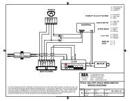
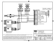
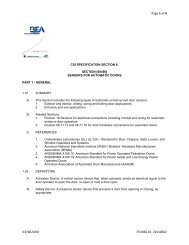
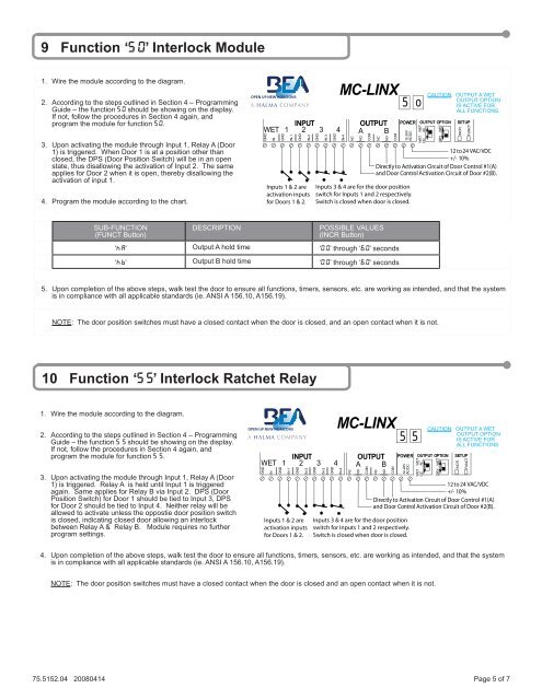
9 Function ‘5 0’ Interlock Module<br />
1. Wire the module according to the diagram.<br />
2. According to the steps outlined in Section 4 – Programming<br />
Guide – the function 5 0 should be showing on the display.<br />
If not, follow the procedures in Section 4 again, and<br />
program the module for function 5 0.<br />
3. Upon activating the module through Input 1, Relay A (Door<br />
1) is triggered. When Door 1 is at a position other than<br />
closed, the DPS (Door Position Switch) will be in an open<br />
state, thus disallowing the activation of Input 2. The same<br />
applies for Door 2 when it is open, thereby disallowing the<br />
activation of input 1.<br />
4. Program the module according to the chart.<br />
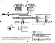
INPUT<br />
WET 1 2 3 4<br />
GND<br />
IN<br />
GND<br />
IN-1<br />
GND<br />
IN-2<br />
Inputs 1 & 2 are<br />
activation inputs<br />
for Doors 1 & 2.<br />
GND<br />
IN-3<br />
GND<br />
<strong>MC</strong>-<strong>LINX</strong><br />
IN-4<br />
NC<br />
OUTPUT<br />
A B<br />
NO<br />
COM<br />
NC<br />
NO<br />
COM<br />
5<br />
POWER OUTPUT OPTION<br />
12-24V<br />
AC/DC<br />
Inputs 3 & 4 are for the door position<br />
switch for Inputs 1 and 2 respectively.<br />
Switch is closed when door is closed.<br />
o<br />
WET<br />
AC<br />
WET<br />
DC<br />
CAUTION: OUTPUT A WET<br />
OUTPUT OPTION<br />
IS ACTIVE FOR<br />
ALL FUNCTIONS.<br />
DRY WET<br />
SETUP<br />
12 to 24 VAC/VDC<br />
+/- 10%<br />
Directly to Activation Circuit of Door Control #1(A)<br />
and Door Control Activation Circuit of Door #2(B).<br />
INCR.<br />
FUNCT.<br />
SUB-FUNCTION<br />
(FUNCT Button)<br />
DESCRIPTION<br />
POSSIBLE VALUES<br />
(INCR Button)<br />
‘H A’ Output A hold time ‘0 0’ through ‘6 0’ seconds<br />
‘H B’ Output B hold time ‘0 0’ through ‘6 0’ seconds<br />
5. Upon completion of the above steps, walk test the door to ensure all functions, timers, sensors, etc. are working as intended, and that the system<br />
is in compliance with all applicable standards (ie. ANSI A 156.10, A156.19).<br />
NOTE: The door position switches must have a closed contact when the door is closed, and an open contact when it is not.<br />
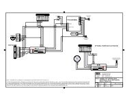
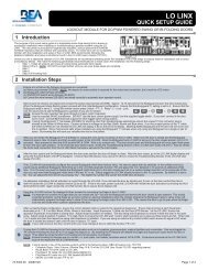
10 Function ‘5 5’ Interlock Ratchet Relay<br />
1. Wire the module according to the diagram.<br />
2. According to the steps outlined in Section 4 – Programming<br />
Guide – the function 5 5 should be showing on the display.<br />
If not, follow the procedures in Section 4 again, and<br />
program the module for function 5 5.<br />
3. Upon activating the module through Input 1, Relay A (Door<br />
1) is triggered. Relay A is held until Input 1 is triggered<br />
again. Same applies for Relay B via Input 2. DPS (Door<br />
Position Switch) for Door 1 should be tied to Input 3, DPS<br />
for Door 2 should be tied to Input 4. Neither relay will be<br />
allowed to activate unless the oppostie door position switch<br />
is closed, indicating closed door allowing an interlock<br />
between Relay A & Relay B. Module requires no further<br />
program settings.<br />
INPUT<br />
WET 1 2 3 4<br />
GND<br />
IN<br />
GND<br />
IN-1<br />
GND<br />
IN-2<br />
Inputs 1 & 2 are<br />
activation inputs<br />
for Doors 1 & 2.<br />
GND<br />
IN-3<br />
GND<br />
<strong>MC</strong>-<strong>LINX</strong><br />
IN-4<br />
NC<br />
OUTPUT<br />
A B<br />
NO<br />
COM<br />
NC<br />
NO<br />
COM<br />
5<br />
POWER OUTPUT OPTION<br />
12-24V<br />
AC/DC<br />
Inputs 3 & 4 are for the door position<br />
switch for Inputs 1 and 2 respectively.<br />
Switch is closed when door is closed.<br />
5<br />
WET<br />
AC<br />
WET<br />
DC<br />
CAUTION: OUTPUT A WET<br />
OUTPUT OPTION<br />
IS ACTIVE FOR<br />
ALL FUNCTIONS.<br />
DRY WET<br />
SETUP<br />
12 to 24 VAC/VDC<br />
+/- 10%<br />
Directly to Activation Circuit of Door Control #1(A)<br />
and Door Control Activation Circuit of Door #2(B).<br />
INCR.<br />
FUNCT.<br />
4. Upon completion of the above steps, walk test the door to ensure all functions, timers, sensors, etc. are working as intended, and that the system<br />
is in compliance with all applicable standards (ie. ANSI A 156.10, A156.19).<br />
NOTE: The door position switches must have a closed contact when the door is closed and an open contact when it is not.<br />
75.5152.04 20080414 Page 5 of 7