MC-LINX - B.E.A., Inc.
MC-LINX - B.E.A., Inc.
MC-LINX - B.E.A., Inc.

You also want an ePaper? Increase the reach of your titles
YUMPU automatically turns print PDFs into web optimized ePapers that Google loves.
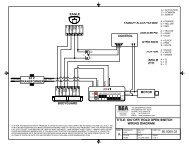
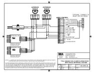
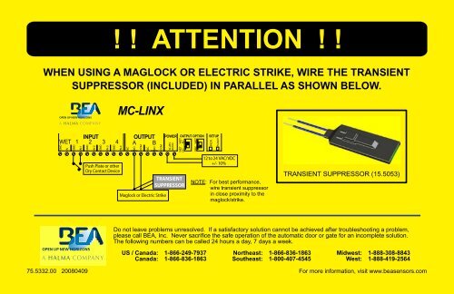
! ! ATTENTION ! !<br />
WHEN USING A MAGLOCK OR ELECTRIC STRIKE, WIRE THE TRANSIENT<br />
SUPPRESSOR (INCLUDED) IN PARALLEL AS SHOWN BELOW.<br />
<strong>MC</strong>-<strong>LINX</strong><br />
WET<br />
GND<br />
IN<br />
INPUT<br />
1 2 3 4<br />
GND<br />
IN-1<br />
GND<br />
IN-2<br />
GND<br />
IN-3<br />
GND<br />
IN-4<br />
NC<br />
OUTPUT<br />
A B<br />
NO<br />
COM<br />
NC<br />
NO<br />
COM<br />
POWER OUTPUT OPTION<br />
12-24V<br />
AC/DC<br />
WET WET<br />
DC AC<br />
DRY WET<br />
SETUP<br />
INCR.<br />
FUNCT.<br />
Push Plate or other<br />
Dry Contact Device<br />
Maglock or Electric Strike<br />
TRANSIENT<br />
SUPPRESSOR<br />
12 to 24 VAC/VDC<br />
+/- 10%<br />
NOTE: For best performance,<br />
wire transient suppressor<br />
in close proximity to the<br />
maglock/strike.<br />
TRANSIENT SUPPRESSOR (15.5053)<br />
Do not leave problems unresolved. If a satisfactory solution cannot be achieved after troubleshooting a problem,<br />
please call BEA, <strong>Inc</strong>. Never sacrifice the safe operation of the automatic door or gate for an incomplete solution.<br />
The following numbers can be called 24 hours a day, 7 days a week.<br />
US / Canada:<br />
Canada:<br />
1-866-249-7937<br />
1-866-836-1863<br />
Northeast:<br />
Southeast:<br />
1-866-836-1863<br />
1-800-407-4545<br />
Midwest:<br />
West:<br />
1-888-308-8843<br />
1-888-419-2564<br />
75.5332.00 20080409 For more information, visit www.beasensors.com
<strong>MC</strong> <strong>LINX</strong> 1 & 2<br />
USER’S GUIDE<br />
PROGRAMMABLE RELAY MODULE<br />
1 Description<br />
The <strong>MC</strong> <strong>LINX</strong> (10<strong>MC</strong><strong>LINX</strong>1 and 10<strong>MC</strong><strong>LINX</strong>2) is a<br />
programmable relay module that may be used for multiple<br />
applications. The module provides removable screw terminal<br />
connectors, and easy 2-button digital programming with a<br />
user-friendly display. The <strong>MC</strong> <strong>LINX</strong> product line is identifi ed<br />
by a blue translucent housing. Check the label on the housing<br />
for the exact <strong>MC</strong> <strong>LINX</strong> model. See table for defined functions.<br />
INCR &<br />
FUNCT<br />
Push<br />
Buttons<br />
Inputs / Outputs<br />
WET Output Selector<br />
FUNCTION EXPLANATION REPLACES BEA MODEL DESCRIPTION<br />
1 0 Timer Module <strong>MC</strong>10 Time delay relay adjustable from 0 0 to 6 0 seconds and has the ability to<br />
accept a normally open or normally closed input.<br />
<strong>MC</strong> <strong>LINX</strong> 2 <strong>MC</strong> <strong>LINX</strong> 1<br />
1 1 Latching Module <strong>MC</strong>11 Sometimes referred to as a ‘ratchet’ relay. Provides a change in the<br />
state of output when triggered, and maintains that state until the input is<br />
triggered again.<br />
2 5 Delay Module <strong>MC</strong>25 Delay on Make, Delay on Break module. Accepts a closure at Input 1,<br />
thus starting a timing sequence for the relays.<br />
7 5 Wet Input Module No Previous Module Same as function 2 5, but with the added ability to accept a ‘WET’ input<br />
from the triggering device. This input is next to Input 1 at the module. A<br />
wet input can be AC or DC, and can accept 12 to 24 volts +/- 10%.<br />
2 1 Sensor Inhibitor LE21 Function 2 1 allows the inhibiting of a door-mounted (non-swing side)<br />
sensor (ie. Superscan) to prevent a ‘push and go’ effect when using the<br />
door manually.<br />
5 0 Interlock Module <strong>MC</strong>50 This module will accept two inputs, and will disallow input 1 while input<br />
2 is active, and disallow input 2 while input 1 is active. Input 1 provides<br />
output to Relay A and input 2 provides an output to Relay B.<br />
5 5 Interlock Module No Previoius Module Provides a interlocking ratchet relay function, whereby Relay A is allowed<br />
to Ratchet only if the door position switch input from Relay B is closed<br />
and vice-a-versa for Relay B.<br />
6 5 Sequencer Module <strong>MC</strong>65 Four inputs will be accepted: Input 1 triggers a sequenced output in<br />
which relay A is held on by the time specifi ed in variable H A, then a delay<br />
specifi ed by variable D i, then relay B is held for a delay specifi ed by H<br />
B. Input 2 triggers a sequenced output in which relay B is held on by the<br />
time specifi ed in variable D B, then a delay specifi ed by variable D O then<br />
relay A is held for a delay specifi ed by H A. Input 3 triggers relay A for<br />
a hold time specifi ed by H A, and Input 4 triggers relay B for a hold time<br />
specifi ed by H B. Each time delay can be set from 0 to 60 secs.<br />
7 5 Wet Input Module No Previous Module Same as function 25, but with the added ability to accept a ‘WET’ input<br />
from the triggering device. This input is next to Input 1 at the module. A<br />
wet input can be AC or DC, and can accept 12 to 24 volts +/- 10%.<br />
2 Specifications<br />
DESCRIPTION<br />
SPECIFICATION<br />
Supply Voltage 12 to 24 VAC/VDC: +/- 10%<br />
Mains Frequency<br />
50/60 Hz<br />
Power Consumption<br />
50mA max. (triggered and with no load)<br />
Temperature Range<br />
-4°F to +131°F<br />
Dimensions<br />
5.2” (133mm) W x 2.2” (55mm) D x 1” (25mm) H<br />
Housing Material<br />
Polycarbonate – Blue Translucent<br />
Input Specifi cation Dry contact input only, except for Function 75 Wet Input: 12 to 24 VAC/VDC: +/- 10%<br />
Output Specifi cation Relay Rating :<br />
Max. switching voltage: 125 VAC, 60VDC<br />
Max. switching current: 1A<br />
Max. switching power: 62.5VA, 30W<br />
‘WET’ Output (at Relay A only) See Section 3 Pre-Installation Tips<br />
75.5152.04 20080414 Page 1 of 7
3 Precautions<br />
<br />
<br />
<br />
<br />
<br />
<br />
<br />
<br />
<br />
<br />
Shut off all power before attempting any wiring procedures.<br />
Maintain a clean & safe environment when working in public areas.<br />
Constantly be aware of pedestrian traffi c around the door area.<br />
Always stop pedestrian traffi c through the doorway when performing tests that may result in unexpected reactions by the door.<br />
ESD: Circuit boards are vulnerable to damage by electrostatic discharge. Before handling ensure you dissipate your body’s<br />
charge.<br />
Always check placement of components before powering up so that moving parts will not catch any wires or cause damage to<br />
equipment.<br />
Ensure compliance with all applicable safety standards (i.e. ANSI A156.10 / 19) upon completion of installation.<br />
When preparing to wire multiple devices together for a ‘system’ confi guration, it is best to ensure the correct operation of each<br />
device independently before starting to help reduce troubleshooting time later, in the event of a discrepancy.<br />
When applying equipment on a new installation, utilizing new electrical supply circuits, always ensure that correct line voltage<br />
exists and is stable. Remember to shut the power back off once this is checked, before performing any wiring to the system.<br />
DO NOT attempt any internal repair of the sensor. All repairs and/or component replacements must be performed by BEA, <strong>Inc</strong>.<br />
Unauthorized disassembly or repair:<br />
1. May jeopardize personal safety and may expose one to the risk of electrical shock.<br />
2. May adversely affect the safe and reliable performance of the product resulting in a voided warranty.<br />
PRECAUTIONS TO OBSERVE WHEN USING A ‘WET’ OUTPUT<br />
<br />
<br />
<br />
<br />
<br />
Never change the switch settings when the module has power<br />
connected to it or when a load is applied.<br />
Never allow 2 different voltage sources to be connected to the<br />
load (electric strike for example) at the same time. This can<br />
result in serious damage to equipment.<br />
If a device is normally being powered by a separate power<br />
source, DO NOT select the ‘Wet’ output option on the <strong>MC</strong><br />
<strong>LINX</strong>. If ‘Wet’ is selected, the next activation of the module<br />
will send a voltage to the load and if there is already a voltage<br />
being applied form another source, the <strong>MC</strong> <strong>LINX</strong> and possibly<br />
the load will be permanently damaged.<br />
When using the ‘Wet’ output option on the <strong>MC</strong> <strong>LINX</strong>, set all desired switch positions (Wet – Dry and AC – DC) before the module<br />
is powered and before any loads are applied.<br />
Ensure there is no other voltage connected to the load. Whatever the input voltage is at the <strong>MC</strong> <strong>LINX</strong>, the output will<br />
correspond. The following can also be observed:<br />
1.<br />
2.<br />
3.<br />
4.<br />
If voltage input at the <strong>MC</strong> <strong>LINX</strong> is AC, then output selection can be AC or DC.<br />
If voltage input at the <strong>MC</strong> <strong>LINX</strong> is DC, then output selection can only be DC.<br />
The maximum load applied to Output A should never exceed 1A. If more than one device is to be connected, add the<br />
consumption values together for a total value. If current is excessive, damage to equipment can result.<br />
On the <strong>MC</strong> <strong>LINX</strong>, the ‘Wet’ output is only available at Output A.<br />
NOTE: WET Output is enabled for all functions.<br />
4 Programming Guide<br />
INPUT<br />
WET 1 2 3 4<br />
GND<br />
IN<br />
GND<br />
IN-1<br />
GND<br />
IN-2<br />
GND<br />
IN-3<br />
GND<br />
<strong>MC</strong>-<strong>LINX</strong><br />
IN-4<br />
NC<br />
OUTPUT<br />
A B<br />
NO<br />
COM<br />
NC<br />
NO<br />
COM<br />
POWER<br />
12-24V<br />
AC/DC<br />
OUTPUT OPTION<br />
WET<br />
AC<br />
WET<br />
DC<br />
DRY WET<br />
SETUP<br />
INCR.<br />
FUNCT.<br />
1. The following are general notes that must be observed while programming for any of the functions available within the <strong>MC</strong> <strong>LINX</strong>:<br />
A. When there is no function set, as is the case on an initinal power on, the user must fi rst press and hold both push buttons (INCR & FUNCT)<br />
for three (3) seconds to activate the display. At his point the display will toggle between FF and 00 every two (2) seconds for ten (10)<br />
seconds overall.<br />
B. FF signals the function that is active and 00 shows that no function is active.<br />
C. By pressing on the INCR button, the user can toggle through each function. A setting of 00 disables the module, and there are no<br />
functions or values active.<br />
D. A display of 10 corresponds to Function10, 11 corresponds to Function 11 and so on. The LE21 function is indicated by a 21.<br />
E. After pressing the INCR push button to select the function, the user can then press the FUNCT button to set the variables defi ned for that<br />
particular function.<br />
F. Once the FUNCT button has been pressed, as to enter into the respective sub-functions & values, the User will not be able to go back<br />
and select a different module designation until the display goes inactive, and the user repeats the above process. This prevents the User<br />
from inadvertently selecting variables from different functions.<br />
G. Note also that when a User holds both push buttons for three seconds, the module is reset to 00 and all variables are cleared.<br />
However at any time during operation the user can press momentarily on the FUNCT push button and the display will become active. In<br />
this way the user can toggle through the variables used only for the module that they have selected. Remember that the INCR push button<br />
always increments the value of the variable that you are looking at, and the FUNCT push button toggles through the available variables.<br />
H. To begin, identify the function that is required for the application. Now press the FUNCT push button until the desired function appears on<br />
the LCD display. Go to the respective section of this manual for setup instructions pursuant to the chosen function. Programming<br />
procedure is the same for the <strong>MC</strong><strong>LINX</strong>1 and <strong>MC</strong><strong>LINX</strong>2.<br />
Page 2 of 7 75.5152.04 20080414
5 Function ‘1 0’ Timer Module<br />
1. Wire the module according to the diagram. The example<br />
shows a typical application requiring a normally open<br />
contact going to an activation circuit for a door control, and<br />
is activated by a normally open switch.<br />
2. According to the steps outlined in Section 4 – Programming<br />
Guide – the function 1 0 should be showing on the display.<br />
If not, follow the procedures in Section 4, again, and<br />
program the module for function 1 0.<br />
3. Press the FUNCT button to toggle to the desired subfunction.<br />
All time-related sub-functions are adjustable in<br />
1 second increments. Press the INCR button to advance.<br />
Press and hold for a rapid succession of numbers. Once 6<br />
0 is reached, the count starts again at 0 0. Sub-functions<br />
for the 1 0 function are shown in the chart. Program the<br />
module as needed for the application.<br />
INPUT<br />
WET 1 2 3 4<br />
GND<br />
IN<br />
GND<br />
IN-1<br />
GND<br />
IN-2<br />
GND<br />
IN-3<br />
GND<br />
<strong>MC</strong>-<strong>LINX</strong><br />
IN-4<br />
Push Plate or other<br />
Dry Contact Device.<br />
NC<br />
OUTPUT<br />
A B<br />
NO<br />
COM<br />
NC<br />
NO<br />
COM<br />
1 0<br />
POWER OUTPUT OPTION<br />
12-24V<br />
AC/DC<br />
WET<br />
AC<br />
WET<br />
DC<br />
Directly to Activation Circuit of<br />
Door Control or Other Device.<br />
CAUTION: OUTPUT A WET<br />
OUTPUT OPTION<br />
IS ACTIVE FOR<br />
ALL FUNCTIONS.<br />
DRY WET<br />
SETUP<br />
INCR.<br />
FUNCT.<br />
12 to 24 VAC/VDC<br />
+/- 10%<br />
SUB-FUNCTION<br />
(FUNCT Button)<br />
DESCRIPTION<br />
POSSIBLE VALUES<br />
(INCR Button)<br />
‘H A’ Output A hold time ‘0 0’ through ‘6 0’. Relay A hold time will not begin counting down until the release of input 1.<br />
‘R L’ Reverse Logic<br />
‘0 0’ = Normal Logic: This means that the input device at Input 1 must be normally open<br />
and close it’s contacts upon triggering.<br />
‘0 1’ = Reverse Logic: This means that the input device at Input 1 must be normally<br />
closed and open it’s contacts upon triggering (Default is ‘0 0’).<br />
4. Once programmimg is complete, trigger the module via Input 1. Observe the time delay and ensure that it is as programmed. The display will<br />
show ‘rA’ when Relay A is energized.<br />
5. Sequence timers will start upon the activation of the inputs. If an input is held closed, relay output A will maintain the changed state and will<br />
begin the countdown of hA once Input A is released released.<br />
6. Upon completion of the above steps, walk test the door to ensure all functions, timers, sensors, etc. are working as intended, and that the system<br />
is in compliance with all applicable standards (ie. ANSI A 156.10, A156.19).<br />
6 Function ‘1 1’ Latching Module<br />
1. Wire the module according to the diagram shown.<br />
2. According to the steps outlined in Section 4 – Programming<br />
Guide – the function 1 1 should be showing on the display.<br />
If not, follow the procedures in Section 4 again, and<br />
program the module for function 1 1.<br />
3. There are no sub-function settings required. The state of<br />
output is not based upon a time delay. The state of relay<br />
output changes if and only if there is a momentary change<br />
of state at Input 1. If Input 1 is maintained, output will<br />
change state once. Input 1 must then be released and retriggered<br />
to change state again.<br />
WET<br />
GND<br />
IN<br />
INPUT<br />
1 2 3 4<br />
GND<br />
IN-1<br />
GND<br />
IN-2<br />
GND<br />
IN-3<br />
GND<br />
IN-4<br />
NC<br />
<strong>MC</strong>-<strong>LINX</strong><br />
OUTPUT<br />
A B<br />
NO<br />
COM<br />
NC<br />
NO<br />
COM<br />
1 1<br />
POWER<br />
12-24V<br />
AC/DC<br />
OUTPUT OPTION<br />
WET<br />
AC<br />
WET<br />
DC<br />
CAUTION: OUTPUT A WET<br />
OUTPUT OPTION<br />
IS ACTIVE FOR<br />
ALL FUNCTIONS.<br />
DRY WET<br />
SETUP<br />
INCR.<br />
FUNCT.<br />
4. Once programmimg is complete, trigger the module<br />
via Input 1. Ensure that Relay A changes state and is<br />
maintained. Trigger Input 1 again, and ensure Relay A<br />
changes state again. When triggered, the display will show<br />
‘11’ for an idle relay, or ‘r1’ for an energized relay.<br />
Push Plate or other<br />
Dry Contact Device.<br />
Directly to Activation Circuit of<br />
Door Control or Other Device.<br />
12 to 24 VAC/VDC<br />
+/- 10%<br />
5. Upon completion of the above steps, walk test the door to ensure all functions, timers, sensors, etc. are working as intended, and that the system<br />
is in compliance with all applicable standards (ie. ANSI A 156.10, A156.19).<br />
75.5152.04 20080414 Page 3 of 7
7 Function ‘2 1’ Activation Inhibitor<br />
1. Wire the module according to the diagram.<br />
2. According to the steps outlined in Section 4 – Programming<br />
Guide – the function 2 1 should be showing on the display. If<br />
not, follow the procedures in Section 4 again, and program<br />
the module for function 2 1.<br />
3. Input 1 is used as the superscan input, Input 2 and Input 3<br />
are used for dry inputs(ie. push plates), and Input 4 is used<br />
for a door position switch. When the door position switch<br />
is closed, the superscan input is ignored, and is only active<br />
after a push plate input. The superscan input will remain<br />
active until the door is closed again, and the process can<br />
repeat.<br />
4. Program the module according to the chart:<br />
INPUT<br />
WET 1 2 3 4<br />
GND<br />
IN<br />
GND<br />
Input 1 for<br />
SuperScan<br />
at approach<br />
side.<br />
IN-1<br />
GND<br />
IN-2<br />
GND<br />
IN-3<br />
GND<br />
Inputs 2 and 3 can<br />
be used for push<br />
plate input or other<br />
activation device.<br />
<strong>MC</strong>-<strong>LINX</strong><br />
IN-4<br />
NC<br />
OUTPUT<br />
A B<br />
NO<br />
COM<br />
NC<br />
NO<br />
COM<br />
2 1<br />
POWER OUTPUT OPTION<br />
12-24V<br />
AC/DC<br />
WET<br />
AC<br />
WET<br />
DC<br />
SETUP<br />
12 to 24 VAC/VDC<br />
+/- 10%<br />
Directly to Activation Circuit of<br />
Door Control or Other Device.<br />
Input 4 is for<br />
the door position<br />
switch. Switch is<br />
closed when door is closed.<br />
CAUTION: OUTPUT A WET<br />
OUTPUT OPTION<br />
IS ACTIVE FOR<br />
ALL FUNCTIONS.<br />
DRY WET<br />
INCR.<br />
FUNCT.<br />
SUB-FUNCTION DISPLAY<br />
(FUNCT Button)<br />
DESCRIPTION<br />
POSSIBLE VALUES<br />
(INCR Button)<br />
REMARKS<br />
‘H A’ Output A hold time ‘0 0’ through ‘6 0’ seconds H A should be set to 2 seconds minimum for a typical<br />
application using a mechanical door position switch.<br />
5. Upon completion of the above steps, walk test the door to ensure all functions, timers, sensors, etc. are working as intended, and that the system<br />
is in compliance with all applicable standards (ie. ANSI A 156.10, A156.19).<br />
8 Function ‘2 5’ Delay Module<br />
1. Wire the module according to the diagram.<br />
2. According to the steps outlined in Section 4 – Programming<br />
Guide – the function 2 5 should be showing on the display.<br />
If not, follow the procedures in Section 4 again, and<br />
program the module for function 2 5.<br />
3. Once programmimg is complete, trigger the module via<br />
Input 1. Ensure that Relay A and Relay B outputs are<br />
functioning according to the programmimg. When the<br />
module is triggered, an ‘R A’ or ‘R B’ will appear in the display.<br />
This indicates that the respective relay is energized.<br />
4. Sequence timers will start upon the activation and release<br />
of the inputs. A re-activation of the input will re-start the<br />
timers, and a maintained input will hold both relays active<br />
indefi nitely - Once Input is released, relay output A & B hold<br />
time will count down normally.<br />
INPUT<br />
WET 1 2 3 4<br />
GND<br />
IN<br />
GND<br />
IN-1<br />
GND<br />
IN-2<br />
GND<br />
IN-3<br />
GND<br />
<strong>MC</strong>-<strong>LINX</strong><br />
IN-4<br />
Push Plate or other<br />
Dry Contact Device.<br />
NC<br />
OUTPUT<br />
A B<br />
NO<br />
COM<br />
NC<br />
NO<br />
COM<br />
2 5<br />
POWER OUTPUT OPTION<br />
12-24V<br />
AC/DC<br />
WET<br />
AC<br />
WET<br />
DC<br />
DRY WET<br />
SETUP<br />
12 to 24 VAC/VDC<br />
+/- 10%<br />
To Activation Circuit<br />
of Door Control<br />
Typically Connected to Lock Device.<br />
When DC Wet Output is Selected for Relay A,<br />
COM Terminal is Positive.<br />
CAUTION: OUTPUT A WET<br />
OUTPUT OPTION<br />
IS ACTIVE FOR<br />
ALL FUNCTIONS.<br />
INCR.<br />
FUNCT.<br />
5. Program the module according to the steps:<br />
SUB-FUNCTION<br />
(FUNCT Button)<br />
DESCRIPTION<br />
POSSIBLE VALUES<br />
(INCR Button)<br />
‘H A’ Output A hold time ‘0 0’ through ‘6 0’ seconds<br />
‘H B’ Output B hold time ‘0 0’ through ‘6 0’ seconds<br />
‘D B’ Delay between Output A & B ‘0 0’ through ‘6 0’ seconds<br />
6. Upon completion of the above steps, walk test the door to ensure all functions, timers, sensors, etc. are working as intended and that the system<br />
is in compliance with all applicable standards (ie. ANSI A 156.10, A156.19).<br />
Page 4 of 7 75.5152.04 20080414
9 Function ‘5 0’ Interlock Module<br />
1. Wire the module according to the diagram.<br />
2. According to the steps outlined in Section 4 – Programming<br />
Guide – the function 5 0 should be showing on the display.<br />
If not, follow the procedures in Section 4 again, and<br />
program the module for function 5 0.<br />
3. Upon activating the module through Input 1, Relay A (Door<br />
1) is triggered. When Door 1 is at a position other than<br />
closed, the DPS (Door Position Switch) will be in an open<br />
state, thus disallowing the activation of Input 2. The same<br />
applies for Door 2 when it is open, thereby disallowing the<br />
activation of input 1.<br />
4. Program the module according to the chart.<br />
INPUT<br />
WET 1 2 3 4<br />
GND<br />
IN<br />
GND<br />
IN-1<br />
GND<br />
IN-2<br />
Inputs 1 & 2 are<br />
activation inputs<br />
for Doors 1 & 2.<br />
GND<br />
IN-3<br />
GND<br />
<strong>MC</strong>-<strong>LINX</strong><br />
IN-4<br />
NC<br />
OUTPUT<br />
A B<br />
NO<br />
COM<br />
NC<br />
NO<br />
COM<br />
5<br />
POWER OUTPUT OPTION<br />
12-24V<br />
AC/DC<br />
Inputs 3 & 4 are for the door position<br />
switch for Inputs 1 and 2 respectively.<br />
Switch is closed when door is closed.<br />
o<br />
WET<br />
AC<br />
WET<br />
DC<br />
CAUTION: OUTPUT A WET<br />
OUTPUT OPTION<br />
IS ACTIVE FOR<br />
ALL FUNCTIONS.<br />
DRY WET<br />
SETUP<br />
12 to 24 VAC/VDC<br />
+/- 10%<br />
Directly to Activation Circuit of Door Control #1(A)<br />
and Door Control Activation Circuit of Door #2(B).<br />
INCR.<br />
FUNCT.<br />
SUB-FUNCTION<br />
(FUNCT Button)<br />
DESCRIPTION<br />
POSSIBLE VALUES<br />
(INCR Button)<br />
‘H A’ Output A hold time ‘0 0’ through ‘6 0’ seconds<br />
‘H B’ Output B hold time ‘0 0’ through ‘6 0’ seconds<br />
5. Upon completion of the above steps, walk test the door to ensure all functions, timers, sensors, etc. are working as intended, and that the system<br />
is in compliance with all applicable standards (ie. ANSI A 156.10, A156.19).<br />
NOTE: The door position switches must have a closed contact when the door is closed, and an open contact when it is not.<br />
10 Function ‘5 5’ Interlock Ratchet Relay<br />
1. Wire the module according to the diagram.<br />
2. According to the steps outlined in Section 4 – Programming<br />
Guide – the function 5 5 should be showing on the display.<br />
If not, follow the procedures in Section 4 again, and<br />
program the module for function 5 5.<br />
3. Upon activating the module through Input 1, Relay A (Door<br />
1) is triggered. Relay A is held until Input 1 is triggered<br />
again. Same applies for Relay B via Input 2. DPS (Door<br />
Position Switch) for Door 1 should be tied to Input 3, DPS<br />
for Door 2 should be tied to Input 4. Neither relay will be<br />
allowed to activate unless the oppostie door position switch<br />
is closed, indicating closed door allowing an interlock<br />
between Relay A & Relay B. Module requires no further<br />
program settings.<br />
INPUT<br />
WET 1 2 3 4<br />
GND<br />
IN<br />
GND<br />
IN-1<br />
GND<br />
IN-2<br />
Inputs 1 & 2 are<br />
activation inputs<br />
for Doors 1 & 2.<br />
GND<br />
IN-3<br />
GND<br />
<strong>MC</strong>-<strong>LINX</strong><br />
IN-4<br />
NC<br />
OUTPUT<br />
A B<br />
NO<br />
COM<br />
NC<br />
NO<br />
COM<br />
5<br />
POWER OUTPUT OPTION<br />
12-24V<br />
AC/DC<br />
Inputs 3 & 4 are for the door position<br />
switch for Inputs 1 and 2 respectively.<br />
Switch is closed when door is closed.<br />
5<br />
WET<br />
AC<br />
WET<br />
DC<br />
CAUTION: OUTPUT A WET<br />
OUTPUT OPTION<br />
IS ACTIVE FOR<br />
ALL FUNCTIONS.<br />
DRY WET<br />
SETUP<br />
12 to 24 VAC/VDC<br />
+/- 10%<br />
Directly to Activation Circuit of Door Control #1(A)<br />
and Door Control Activation Circuit of Door #2(B).<br />
INCR.<br />
FUNCT.<br />
4. Upon completion of the above steps, walk test the door to ensure all functions, timers, sensors, etc. are working as intended, and that the system<br />
is in compliance with all applicable standards (ie. ANSI A 156.10, A156.19).<br />
NOTE: The door position switches must have a closed contact when the door is closed and an open contact when it is not.<br />
75.5152.04 20080414 Page 5 of 7
11 Function ‘6 5’ Sequencer Module<br />
1. Wire the module according to the diagram.<br />
2. According to the steps outlined in Section 4 – Programming<br />
Guide – the function 6 5 should be showing on the display.<br />
If not, follow the procedures in Section 4 again, and<br />
program the module for function 6 5.<br />
3. A sequenced operation can be obtained by triggering<br />
Input 1 or Input 2. When Input 3 or 4 is triggered, it only<br />
activates Door 1 (relay A) or Door 2 (relay B) respectively<br />
(for example, for use with vestibule switches for entrapment<br />
purposes).<br />
4. Sequence timers will start upon the activation and release of<br />
the inputs. A re-activation of the input will re-start the timers<br />
and a maintained input will trigger the relays according to<br />
the program values, but will hold relay output A & B active<br />
until the input is released.<br />
5. Program the module according to the chart:<br />
INPUT<br />
WET 1 2 3 4<br />
GND<br />
IN<br />
GND<br />
IN-1<br />
GND<br />
IN-2<br />
GND<br />
IN-3<br />
GND<br />
<strong>MC</strong>-<strong>LINX</strong><br />
IN-4<br />
NC<br />
OUTPUT<br />
A B<br />
NO<br />
COM<br />
NC<br />
NO<br />
COM<br />
POWER OUTPUT OPTION<br />
12-24V<br />
AC/DC<br />
WET<br />
AC<br />
WET<br />
DC<br />
SETUP<br />
12 to 24 VAC/VDC<br />
+/- 10%<br />
Directly to Activation Circuit of Door Control #1(A)<br />
and Door Control Activation Circuit of Door #2(B).<br />
Input 4 allows activation of Door #2 with no sequence to Door #1.<br />
Input 3 allows activation of Door #1 with no sequence to Door #2.<br />
Input 2 allows sequenced activation from Door #2 to Door #1.<br />
Input 1 allows sequenced activation from Door #1 to Door #2.<br />
6<br />
5<br />
CAUTION: OUTPUT A WET<br />
OUTPUT OPTION<br />
IS ACTIVE FOR<br />
ALL FUNCTIONS.<br />
DRY WET<br />
INCR.<br />
FUNCT.<br />
SUB-FUNCTION<br />
(FUNCT Button)<br />
DESCRIPTION<br />
POSSIBLE VALUES<br />
(INCR Button)<br />
‘H A’ Output A (Door 1) hold time ‘0 0’ through ‘6 0’ seconds<br />
‘H B’ Output B (Door 2) hold time ‘0 0’ through ‘6 0’ seconds<br />
‘D I’ Delay from Output A (Door 1) to Output B (Door 2) ‘0 0’ through ‘6 0’ seconds<br />
‘D O’ Delay from Output B (Door 2) to Output A (Door 1) ‘0 0’ through ‘6 0’ seconds<br />
6. Upon completion of the above steps, walk test the door to ensure all functions, timers, sensors, etc. are working as intended and that the system<br />
is in compliance with all applicable standards (ie. ANSI A 156.10, A156.19).<br />
12 Function ‘7 5’ Wet Imput Module<br />
1. Wire the module according to the diagram shown.<br />
2. According to the steps outlined in Section 4 – Programming<br />
Guide – the function 7 5 should be showing on the display.<br />
If not, follow the procedures in Section 4 again, and<br />
program the module for function 7 5.<br />
3. Once programmimg is complete, trigger the module via<br />
the ‘Wet’ Input. Ensure that Relay A and Relay B outputs<br />
are functioning according to the programmimg. When the<br />
module is triggered, an ‘R A’ or ‘R B’ will appear in the display.<br />
This indicates that the respective relay is energized.<br />
4. Sequence timers will start upon the activation and release<br />
of the inputs. A re-activation of the input will re-start the<br />
timers, and a maintained input will hold the relays active.<br />
Once Input is released, Relay A & B hold time will count<br />
down normally.<br />
INPUT<br />
WET 1 2 3 4<br />
GND<br />
IN<br />
+ -<br />
‘Wet’<br />
Input<br />
12 to 24<br />
VAC/DC<br />
+/- 10%<br />
GND<br />
IN-1<br />
GND<br />
IN-2<br />
GND<br />
IN-3<br />
GND<br />
Input 1 is for an<br />
additional ‘Dry’<br />
input device.<br />
<strong>MC</strong>-<strong>LINX</strong><br />
IN-4<br />
NC<br />
OUTPUT<br />
A B<br />
NO<br />
COM<br />
NC<br />
NO<br />
COM<br />
7 5<br />
POWER OUTPUT OPTION<br />
12-24V<br />
AC/DC<br />
WET<br />
AC<br />
WET<br />
DC<br />
DRY WET<br />
SETUP<br />
12 to 24 VAC/VDC<br />
+/- 10%<br />
To Activation Circuit<br />
of Door Control<br />
Typically Connected to Lock Device.<br />
When DC Wet Output is Selected for Relay A,<br />
COM Terminal is Positive.<br />
CAUTION: OUTPUT A WET<br />
OUTPUT OPTION<br />
IS ACTIVE FOR<br />
ALL FUNCTIONS.<br />
INCR.<br />
FUNCT.<br />
5. Be sure to set the ‘Output Option’ dipswitches to their correct position. The output voltage is equal to the input voltage.<br />
If AC is input, then AC or DC is available for output. If DC is input, then only DC will be available for output.<br />
6. Program the module according to the chart:<br />
SUB-FUNCTION<br />
(FUNCT Button)<br />
DESCRIPTION<br />
POSSIBLE VALUES<br />
(INCR Button)<br />
‘H A’ Output A hold time ‘0 0’ through ‘6 0’ seconds<br />
‘H B’ Output B hold time ‘0 0’ through ‘6 0’ seconds<br />
‘D B’ Delay from Output A to Output B ‘0 0’ through ‘6 0’ seconds<br />
7. Upon completion of the above steps, walk test the door to ensure all functions, timers, sensors, etc. are working as intended, and that the system<br />
is in compliance with all applicable standards (ie. ANSI A 156.10, A156.19)<br />
Page 6 of 7 75.5152.04 20080414
13 Documentation<br />
1. Document all work. For future reference, be sure to record the <strong>MC</strong> <strong>LINX</strong> Serial Number on your Work Order.<br />
2. Educate the Owner / Manager as to the proper operation of the door and sensor system, and what to do to ensure safe use of the door in the<br />
event of discovering a malfunction. Show the Owner / Manager how to perform a daily safety check of the system.<br />
3. Be sure to obtain signatures on your work order for all work accomplished.<br />
14 Troubleshooting<br />
PROBLEM PROBABLE CAUSE CORRECTIVE ACTION<br />
Module will NOT react to any input. 1. <strong>Inc</strong>orrect power input<br />
2. Module not programmed<br />
3. <strong>Inc</strong>orrect wiring<br />
4. Faulty module<br />
1. Check input power. Should be 12 to 24 volts AC or DC +/- 10%. Ensure<br />
that input power is applied at the correct terminals.<br />
2. Ensure a function has been programmed. If ‘- -‘ is showing in the display,<br />
the module will need to be programmed.<br />
3. Jumper an active input and ensure that the fault is not within the wiring.<br />
If module works when jumpered, trace wiring from Inputs / outputs.<br />
4. Replace module.<br />
Module reacts to input but has no<br />
output.<br />
1. Wrong outputs are<br />
connected<br />
2. <strong>Inc</strong>orrect wiring<br />
3. Faulty module<br />
1. Check to ensure that the proper outputs are connected per the function<br />
selected.<br />
2. Trace all wiring to ensure correct termination points<br />
3. Replace module<br />
15 Company Contact<br />
Do not leave problems unresolved. If a satisfactory solution cannot be achieved after troubleshooting a problem, please<br />
call BEA, <strong>Inc</strong>. If you must wait for the following workday to call BEA, leave the door inoperable until satisfactory repairs<br />
can be made. Never sacrifi ce the safe operation of the automatic door or gate for an incomplete solution.<br />
The following numbers can be called 24 hours a day, 7 days a week. For more information, visit www.beasensors.com.<br />
US and Canada:<br />
Canada:<br />
Northeast:<br />
1-866-249-7937<br />
1-866-836-1863<br />
1-866-836-1863<br />
Southeast:<br />
Midwest:<br />
West:<br />
1-800-407-4545<br />
1-888-308-8843<br />
1-888-419-2564<br />
75.5152.04 20080414 Page 7 of 7