2 Specifications USER'S GUIDE 1 Description
2 Specifications USER'S GUIDE 1 Description
2 Specifications USER'S GUIDE 1 Description

You also want an ePaper? Increase the reach of your titles
YUMPU automatically turns print PDFs into web optimized ePapers that Google loves.
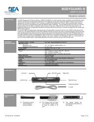
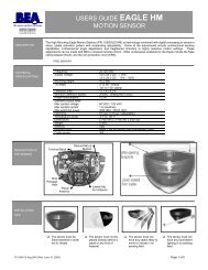
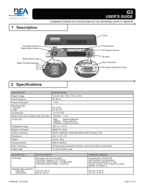
1 <strong>Description</strong>G3USER’S <strong>GUIDE</strong>COMBINED RADAR ACTIVATION AND ACTIVE INFRARED SAFETY SENSORCover2nd Radar AntennaRadar Motion SensorPush ButtonsIR Presence SensorRadar Antenna ClipRadar Tilt Angle Indication45°30°15°IR PrismMain ConnectorIR Curtain Adjustment Screw2 <strong>Specifications</strong>DESCRIPTIONSPECIFICATIONSupply voltage 12 to 24 VAC / VDC: -5% to +10%Power frequencyPower consumptionMounting height• Standard• High50 / 60 Hz< 3 W5’9” to 8’2”8’2” to 13’0”G3 data input 10 to 30 VDCDelay of the output activation after stimulationTransistor : < 1ms3-color LED • RED: presence detection• GREEN: motion detection• ORANGE: monitoring processTemperature rangeDegree of protectionProduct conformity-30°F to +131°FNEMA 3S / (IP54)Dimensions 10.4“ x 2.2“ x 1.9“WeightHousing materialColor of HousingCable lengthR&TTE 1999/5/EC & EMC 89/336/EEC BZT Germany, TÜV.55 lbs / 250 gABS & LURAN SAnthracite gray (standard), aluminum, dark bronze, black or white finish10’ of 6-conductor cableDESCRIPTION MOTION SENSOR PRESENCE SENSORTechnologyMicrowave and microprocessorTransmitter frequency: 24.125 GHzTransmitter radiated power:
2 <strong>Specifications</strong> (Continued)DESCRIPTION MOTION SENSOR PRESENCE SENSORDetection modeMinimum detection speed2 inches / sec. (measured in the sensor axis)Response time: < 128msAngle From 15° to 50° in elevation (adjustable) From - 4° to + 4° (adjustable)Output specificationRelay (free of potential change-over contact):• Max contact voltage: 42V AC/DC• Max contact current: 1A (resistive)• Max switching power: 30W (DC) / 60VA (AC)Output hold-time 0.5s to 9s (adjustable) 1s (fixed)Manual adjustmentRemote control adjustments• orientation of sensing field (mechanically)• shape of the sensing field (choice of antenna)• multiple functions (using push buttons)• Sensitivity• Hold time• Detection mode• Immunity• Output configurationTransistor (optocoupled transistor)• Max output current: 100 mA• Max switching power: 48 VDC• orientation of sensing field• shape of the sensing field (choice of front lens)• multiple functions (by push buttons)• Immunity• Auto-learn time• Monitoring mode• Number of Curtains• Relay / Output configuration3 PrecautionsShut off all power before attempting any wiring procedures.Maintain a clean & safe environment when working in public areas.Constantly be aware of pedestrian traffic around the door area.Always stop pedestrian traffic through the doorway when performing tests that may result in unexpected reactions by thedoor.ESD electrostatic discharge: Circuit boards are vulnerable to damage by electrostatic discharge. Before handling any boardensure you dissipate your body’s charge.Always check placement of all wiring before powering up to insure that moving door parts will not catch any wires and causedamage to equipment.Ensure compliance with all applicable safety standards (i.e. ANSI A156.10 / 19) upon completion of installation.DO NOT attempt any internal repair of the sensor. All repairs and/or component replacements must be performed by BEA,Inc. Unauthorized disassembly or repair:1. May jeopardize personal safety and may expose one to the risk of electrical shock.2. May adversely affect the safe and reliable performance of the product will result in a voided product warranty.4 Pre Installation Check1. When preparing to wire multiple devices together for a ‘System’ configuration, it is best to ensure the correct operation of each device independentlybefore starting to help reduce troubleshooting time later in the event of a discrepancy.2. Prior to installing any equipment, ensure the correct line voltage and stability. When applying equipment on a new installation utilizing newelectrical supply circuits, always ensure that correct line voltage exists and is stable. Remember to shut the power back off after this ischecked and before performing any wiring to the system.5 Installation1 Remove Sensor Cover1. Remove cover from unit by gently prying the tab on the backside ofthe sensor housing or if the sensor is installed on the header inserta screwdriver behind the unit and gently pry off the cover.TabPryPage 2 of 15 75.5640.02 20110330
Drill 1/8” hole1/41/23/411-1/41-1/21-3/42Drill 1/2” wire passage hole anywhere within this areaDo not mount lower than this lineDo not mount lower than this lineDrill 1/8” hole1/41/23/411-1/41-1/21-3/425 Installation (Continued)2 Mount SensorG3 MOUNTING TEMPLATE1. Using scale on template, position drawing of sensor on template0” to 2” from bottom of header.NOTE: Flush mount with bottom of header is necessary for allnegative IR angles.2. Drill hole marked for wire passage and drill pilot holes for screwmounting. Remove template prior to sensor installation.3. Insert mounting screws approximately halfway in and install the G3on the screws. When in place, tighten screws to secure to header.NOTE: Leave cover off until mechanical adjustments are complete.3 Cable Routing1. With G3 in place, locate the enclosed cable and feed the strippedend through the wire passage hole in the header.2. Leave enough slack to allow connection to the G3 and properrouting of wire around the plastic post.NOTE: Observe proper routing of the cable as shown. This isto divert rainwater from the G3 if water should run downthe cable. Proper routing of the wire also provides easierinstallation of the cover.Plastic PostCable / Wire4 Sensor Wiring1. When connecting to a microprocessed control box, the motion output and presence output wires may be connected to separate inputs or mayalso be connected to a mutual input. Some controls may only have an activation input, while others may have an activation input, as well as asafety (or presence) input.OPTION1OPTION2OPTION3ColorWiring the G3 to an Automatic Door Control with Separate Activation and Safety InputsMicroprocessed ControlsRed 12 to 24 VAC / VDC: -5% to +10%Black 12 to 24 VAC / VDC: -5% to +10%WhiteGreenBrownBlueColorCommon at Door ControlActivation Input at Door ControlCommon at Door ControlSafety Input at Door ControlWiring the G3 to an Automatic Door Control with Activation and Safety Wired to One InputControls Without Safety CircuitRed 12 to 24 VAC / VDC: -5% to +10%Black 12 to 24 VAC / VDC: -5% to +10%WhiteGreenBrownBlueColorCommon at Door ControlActivation Input at Door ControlCommon at Door ControlActivation Input at Door ControlWiring the G3 to an Automatic Door Control with Activation and Safety Signal through Relay OnlyControls Without Safety CircuitRed 12 to 24 VAC / VDC: -5% to +10%Black 12 to 24 VAC / VDC: -5% to +10%WhiteGreenBrownBlueCommon at Door ControlActivation Input at Door ControlNot UsedNot UsedWIZARDWIZARDWIZARD• PWR: Red - 12 to 24 VAC / VDC: -5% to +10%• PWR: Black - 12 to 24 VAC / VDC: -5% to +10%• COM: White - Common at Door Control• ACTIV: Green - Activation at Door Control• COM: Brown - Common at Door Control• SAFETY: Blue - Safety at Door ControlFor Secondary Activation see important note on page 6.For One Way Evening Mode see addendum 5 on page 15.• PWR: Red - 12 to 24 VAC / VDC: -5% to +10%• PWR: Black - 12 to 24 VAC / VDC: -5% to +10%• COM: White - Common at Door Control• ACTIV: Green - Activation at Door Control• COM: Brown - Connected to White Common• SAFETY: Blue - Connected to Green ActivationBrown and Blue may be connected to White and Green• PWR: Red - 12 to 24 VAC / VDC: -5% to +10%• PWR: Black - 12 to 24 VAC / VDC: -5% to +10%• COM: White - Common at Door Control• ACTIV: Green - Activation at Door ControlWhite and Green provide output for motion and presence detectionOn Remote Control Set:F1 To 1CONTROLCONTROLCONTROL75.5640.02 20110330 Page 3 of 15
6 Mechanical Adjustments1 Radar Motion Sensing Field: Width06.4’3.2’0 3.2’ 6.4’06.4’3.2’0 3.2’ 6.4’3.2’3.2’6.4’6.4’9.6’Wide Pattern9.6’Narrow Pattern1. Insert the desired microwave antenna for a wide or narrow field of detection. The optional narrow field antenna is located in the slot behindthe mounted antenna as shown. To remove the antenna, carefully remove the protective cover and change the antenna. Once the properantenna is in place, adjust the angle of antenna as necessary.2 Radar Motion Sensing Field: Depth06.4’3.2’0 3.2’ 6.4’06.4’3.2’0 3.2’ 6.4’3.2’6.4’9.6’3.2’6.4’9.6’45°30°0° 15°13.1’ 15° 30° 45°1. The position of the sensing field is determined by the vertical angle of the planar antenna. The angle is adjusted by gently rotating theantenna forward or backward. The default angle is 30°.2. The tilt angle is determined by the position of the sensor with relation to the face of the door. A 15° angle will result in the pattern being drawnback toward the door. A 45° angle will place the pattern further away from the door. Be certain to walk test the detection field and ensurecompliance with applicable ANSI standards.3 IR Presence Sensing Field: Width7.2’7.2’14”6.5’14”3.2’Wide PatternNarrow Pattern1. Install the lens for the desired IR pattern. The wide pattern offers 2 curtains of 24 overlapping spots and the narrow pattern offers 2 curtains of12 overlapping spots. When installing the lens ensure the smooth part of the lens is installed facing outward.4 IR Presence Sensing Field: Depth0°-4°+4° -4°0°max. 3” max. 3”Sensor Plastic Pin IndicatorSensor Adjustment Screw1. The IR pattern may be adjusted by moving the pattern nearer or further away from the face of the door by adjusting the tilt angle from +4° to-4°. A counterclockwise rotation of the adjustment screw will move the curtain further away from the door and clockwise rotation will move thecurtain toward the door. Precise location of the IR beam may be found by using BEAs Spotfinder P/N 10SPOT.Page 4 of 15 75.5640.02 20110330
7 Remote Control Adjustments1 Important Remote Control AdjustmentsEvery programming session begins by unlocking the sensor. Thereafter a program setting may be altered by pressing the desired function keyfollowed by the desired value for that function. When all programming is complete press the lock key twice to retain settings. Use the followingas a guide:Unlock the sensor to enter into adjustmentsession (if no access code has been entered)Press Unlock KeyRED LEDFlashes SlowlyTo change the value of a parameter(ex. Maximum duration of presencedetection)Select Parameterto ChangeRED LEDFlashes Quickly0-9Enter New ValueRED LEDFlashes Slowly… to change any other parameters(ex. Output Configuration)Select Parameterto ChangeRED LEDFlashes Quickly0-9Enter New ValueRED LEDFlashes SlowlyTo check the value of a parameter(ex. maximum duration of presencedetection)Select Parameterto CheckRED LEDFlashes Quickly?Press QuestionMarkThe Number of Green Flashes Indicatethe Value of This ParameterRED LEDFlashes SlowlyLock the adjustment session and go back tonormal functionPress Lock Key TwiceOR+ Lock CodeSafety OutputRedirection F10: No Redirection1: Transfer Presence Detection ToActivation Output (All Relay Output)2: Activation Output Only Upon Motionand Presence Detection0 (0.5s) → 9 (9s)Relay Hold TimeSensitivity0 (min) → 9 (max) default = 76.4’ 3.2’ 0 3.2’ 6.4’0033.2’696.4’9.6’UnlockCheck Value ?LockMicrowave DetectionMode1: Bidirectional Mode2: Unidirectional Mode3: Unidirectional Mode with MTFRadar Motion DetectionIR Presence Detection1 2 3 A47F1580+?69F2BCDInstallationConfigurationMountingHeightDoor ControlPulseFrequencySingle Unit1 Low Low2 High Low3 Low High4 High HighOverlapping Units5 Low Low6 High Low7 Low High8 High HighSee Important Notes Page 61: Normal (LED in Normal Mode)2: Door Permanently Open(Red LED On)3: Door Permanently Closed(Red LED Off)F2MicrowaveImmunity1: Reduced2: Normal3: Increased4: through 9: Higher number equalshigher immunity level.See Important Notes Page 675.5640.02 20110330 Page 5 of 15
7 Remote Control Adjustments (Continued)2 Important Remote Control AdjustmentsImportant Notes• Defaults are Shown in Bold Print• Restore Factory DefaultsMagic Wand + 9Sensor will Self Launch Set Up• Quick Set Up has Two SecondDuration• Assisted Set Up is recommendedfor first time set up. Duration is16 seconds and will automaticallytrigger door to open position duringset up routine.Microwave Immunity: Immunitylevels above 3 are intended forapplications where excessiveinterference may be causingunintended detection. When applyinga value of 4 or higher increment thevalue one step at a time followed bya walk test. When complete, ensurecompliance with all applicable safetyand performance standards.Secondary Activation: On a one-waytraffic application, use a toggle switchor other switch to break the green wireto door control. Door control safetycircuit must turn off in door closedposition.Installation Configuration: Toprevent crosstalk when installingoverlapping units set one unit to 5 andone unit to 7 for Low mount or one unitto 6 and one unit to 8 for High mount.Reset access code to default: Powercycle the sensor and within 60 sec.press unlock, lock, lock.Radar Motion DetectionIR Presence Detection1 2 3 A47F1580+?69F2BCDNumber of IR Curtains1: 1 Curtain(Safety Curtain Close to the Door)2: 2 Curtains3: 2nd Curtain in Dynamic Mode(Enabled After a Motion Detection)SecondaryActivation Sensitivity0 (min) → 9 (max) default = 06.4’ 3.2’ 0 3.2’ 6.4’0033.2’696.4’9.6’OutputConfigurationMotionOutPresenceOut1 Active / N.O. Passive / N.C.2 Passive / N.C. Active / N.O.3 Passive / N.C. Passive / N.C.4 Active / N.O. Active / N.O.Automatic Learn Time0: 30 Seconds 4: 10 Minutes1: 1 Minute 5: 20 Minutes2: 2 Minutes 6: 60 Minutes3: 5 Minutes 9: InfinityNo LearnSetupInfrared Immunity1: Normal2: High (extreme snow, rain, pedimatsor lighting)See Important Notes09Launch Quick SetupLaunch Assisted SetupRestore Factory SettingsNote: F1 function and theaccess code are not reset.3 Launch Set Up of Infrared CurtainsUnlock the sensor to enter into adjustmentsessionTo Launch an Assisted Set Up→ Required after mechanical adjustments ofthe IR sensor module→ Required once after first installationPress Unlock KeyRED LEDFlashes Slowly0Press Set Up Press 0RED / GREEN LEDAlternating FlashesThe sensor performs a door opening andclosing cycle to check the influence of thedoor leaves to the safety curtains. SeeTroubleshooting if RED LED flashes quicklyafter set up.Page 6 of 15 75.5640.02 20110330
9 Power Up1 Power Up ProceduresSTEP USER’S ACTION RESULTStep 1 With all wiring in place, apply power to door control and 12 to 24VAC / VDC: -5% to +10% to G3. Once powered, observe LEDstatus on the G3. Stop all traffic through the doorway while performingthis step, and remain clear of the G3’s detection zones.Step 2Step 3If the sensor is being powered for the first time, because of newinstallation or sensor is being replaced, unlock the G3 and Pressthe Magic Wand Key, followed by a number 0. Observe the LEDstatus during setup.Once set-up is complete, the LED indication will reflect thestatus of the set-up. Observe the LED while standing outside ofthe detection zones.Proceed with fine tuning the mechanical , as well as the programadjustments of the G3. Refer to the applicable sections of thismanual for altering any settings. Be sure to check:• Motion width & depth• Presence width & depth• Position of infrared curtain • Sensitivity of motion fieldThe G3 will show a steady red LED during the set-up procedure.Once the G3 completes setup, the door will close and beginnormal operation thereafter. Setup process takes approximately6 seconds, if uninterrupted.• NO LED UPON COMPLETION = Successful setup• RED LED ON = Presence being detected -G3 is seeing anobject.• GREEN LED MOMENTARILY ON = MOTION DETECTION(G3 sees movement). Adjust microwave functions: angle,sensitivity, immunity.• ORANGE LED ON = Possible fault. If LED stays on, resetpower and observe LED. If it comes back on steady, replaceG3.• Fast flashing Red = setup failed due to improper IR curtainadjustment or disturbance of IR curtain during setup.Sensor must always be adjusted to be in compliance with thecurrent version of ANSI A156.10.10 Troubleshooting1 Troubleshooting ProceduresPROBLEM PROBABLE CAUSE CORRECTIVE ACTIONOrange LED is illuminated on G3.Red LED flashes after attempting a set-up.Door will not close Red LED off at G3.1. G3 IR is in saturation2. Internal fault within the G33. Faulty Power Input1. Infrared curtains are too close to the doorand the sensor detects a door influence.2. IR curtain too far away from door.3. IR curtain disturbed during setup.1. On-Off switch at door control in wrongposition or is faulty.2. Improper Relay Configuration on G3.3. Faulty door control.1. Launch a new setup and remain all clearfrom the detection area.2. Remove power, then re-apply. Input powermay have fluctuated beyond tolerances.1. Adjust Infrared curtain as necessary. Useof BEA’s Spotfinder during this process isrecommended.2. Adjust Infrared curtain as necessary. Useof BEA’s Spotfinder during this processisrecommended.3. Relaunch a setup and keep people awayfrom door until setup completes.1. Check to insure On-Off switch for door is inthe ON or AUTOMATIC position. If switchis in correct position, check switch withmulti-meter for proper operation.2. Insure correct polarity at Brown and Bluewires3. Check Relay Configuration setting on eachG3. Refer to page 6 for settings.4. Remove all sensor inputs from the doorcontrol. If door remains open, fault existswith door control or motor. Referto manufacturer’s manual for furthertroubleshooting. If door closes with sensorinputs removed, fault exists with sensors orrelated wiring.Page 8 of 15 75.5640.02 20110330
10 Troubleshooting (Continued)1 Troubleshooting ProceduresPROBLEM PROBABLE CAUSE CORRECTIVE ACTIONDoor opens when it should close. 1. Relay Configuration on wrong setting. 1. Check Relay Configuration setting.Door will not open.Door will not open (Continued).Door keeps recycling open.G3 will not respond to remote control.G3 will not unlock when access code isentered.1. On-Off switch at door control in wrongposition or is faulty.1. G3 not detecting traffic.2. Faulty wiring between sensor and doorcontrol.3. Faulty door control.1. G3 is seeing door.2. G3 is seeing movement from unwantedobjects.3. Vibration is triggering the G3.1. Batteries in remote are dead or areinstalled improperly.1. Check to insure On-Off switch for door is inON or AUTOMATIC position. If it is in correctposition, check switch with multi-meterfor proper operation.1. Walk in and out of G3 detection area, ifgreen LED does not illuminate check:a. Power supply for G3: 12 to 24 VAC /VDC: -5% to +10%b. Check G3 setting on each G3.c. Check Relay Configuration for eachG3.2. Remove all sensor inputs from the doorcontrol. Jumper the common and activateterminals of the door control. If door doesnot open, fault lies within door control ormotor. Refer to manufacturer’s manual forfurther troubleshooting. If door opens, faultlies with sensors or related wiring.3. Refer to Step 2.1. Observe LED status on each G3. GreenLED indicates motion detection, redLED indicates presence. If LED’s are on,make sensor adjustments as necessaryto eliminate unwanted detection. Checkangle, sensitivity, and immunity forpresence and motion.2. Check for moving objects in the path ofdetection, such as posters, banners, etc.3. Locate source of vibration and correct asnecessary.1. Ensure batteries are installed correctly.Replace batteries: AAA 1.5 volt.1. Improper code being entered. 1. Reset code to the default value of 0000 byperforming the following:a. Cut and restore power supply. No codeis required to unlock during the firstminute after powering. Reset code priorto locking.11ANSI / AAADM ComplianceAAADMAmerican Association ofAutomatic Door ManufacturesUpon finishing the installation and/or service work perform at a minimum a daily safety check in accordance with theminimum inspection guidelines provided by AAADM. Provide each owner with an owner’s manual that includes a dailysafety checklist and contains at a minimum the information recommended by AAADM. Offer a familiarization sessionwith the owner explaining how to do daily inspections and calling out location of cutoff switches to put equipment outof service if a deficiency is noted. The equipment should be inspected in accordance with the minimum inspectionguidelines annually. A safety check that includes at a minimum the items listed on the safety information label must beperformed during each service call. If you are not an AAADM certified inspector BEA strongly recommends to have anAAADM certified inspector perform an AAADM inspection and placing a valid inspection sticker below the safetyinformation label prior to placing the equipment into operation.75.5640.02 20110330 Page 9 of 15
12 AccessoriesCeiling Adapter10WCAUniversal Rain Cover10URCWeather / Rain Cover10WRCSpotfinder10SPOTCable Adapter10IFBWIZARDII13 Company ContactDo not leave problems unresolved. If a satisfactory solution cannot be achieved after troubleshootinga problem, please call BEA, Inc. If you must wait for the following workday to call BEA, leave the doorinoperable until satisfactory repairs can be made. Never sacrifice the safe operation of the automaticdoor or gate for an incomplete solution.Our Service Technicians can be called 24 hours a day, 7 days a week. For more information visit www.beasensors.com.West / Mexico1-888-419-2564Phone: 1-800-523-2462 Fax: 1-888-523-2462After Normal Business HoursCentral1-800-407-4545AK, MI, WI, TX, Canada1-866-836-1863East1-866-249-7937Page 10 of 15 75.5640.02 20110330
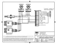
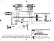
Addendum 1EXTERIOR WIZARD/G3SAFETYblueCOMbrownACTIVATIONgreenCOMwhitePOWERblackPOWERredSAFETYblueCOMbrownACTIVATIONgreenCOMwhitePOWERblackPOWERredDURAGLIDE INTERFACE BOARDTB- 3123 COMMON45678 HOLDINGBEAMSCOMMONINTERIOR SCANTB- 21234567824 VTRANSFORMERCOMMONEXTERIOR SCAN* RECEIVER (A), EMITTER (A)RECEIVER (B), EMITTER(B)WH= WHITE, BL= BLACKMICROCELL ONERA WH 1RA BL 2EA WH 3EA BL 45 NC4 NO3 COM2 12-24 VAC/DC1 12-24 VAC/DCON1 2 3 4SEE NOTE 2RB WH 1RB BL 2EB WH 3EB BL 4100 ENTERPRISE DRIVEPITTSBURGH, PA 15275PHONE: (412) 249-4100FAX: (412) 249-4101EMAIL: www.beasensors.comTITLE: STANLEY DURAGLIDE WITHWIZARD II /G3 SYSTEM,MICROCELLNOTES: 1) WIZARDS WILL OPERATE WITH THE 12 VDC ON PINS 1&2, 5&6.2) ONE WAY FUNCTION IS APPLICABLE IF CLOSED DOOR MONITORING SWITCH IS INSTALLED.SWITCH SHALL CLOSE 2" FORM FULL CLOSEPART NO:REV BY:SIZE: DRAWN BY:KJG TUC 80.0123.04SHEET1 OF 1SCALE: DATE:NONE 24 NOV 2005AIF AFTER TROUBLESHOOTING A PROBLEM, A SATISFACTORY SOLUTION CANNOT BE ACHIEVED, PLEASE CALL B.E.A., INC.FOR FURTHER ASSISTANCE DURING EASTERN STANDARD TIME AT 1-800-523-2462 FROM 8AM - 5PM. FOR AFTER-HOURS,CALL EAST COAST: 1-866-836-1863 OR 1-800-407-4545 / MID-WEST: 1-888-308-8843 / WEST COAST: 1-888-419-2564. DO NOTLEAVE ANY PROBLEM UNRESOLVED. IF YOU MUST WAIT FOR THE FOLLOWING WORKDAY TO CALL B.E.A., LEAVE THEDOOR INOPERABLE UNTIL SATISFACTORY REPAIRS CAN BE MADE. NEVER SACRIFICE THE SAFE OPERATION OF THEAUTOMATIC DOOR OR GATE FOR AN INCOMPLETE SOLUTION.WEB: WWW.BEASENSORS.COMPage 11 of 15 75.5640.02 20110330
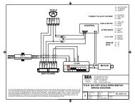
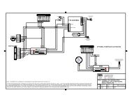
OFFSTOP IMPULSEPRES. IMPULSE(1)C-SWITCH, 0 VDCPRES. IMPULSE(2)INNER IMPULSEOUTER IMPULSE*Addendum 2AMD2 CONTROLR12345678910111213141516RESETPARTIAL OPENEXIT+ 18 VDC+ 18 VDC* Optional - connectto reset (TB1 R) if required.} LOCKING DEVICE100 ENTERPRISE DRIVEPITTSBURGH, PA 15275PHONE: (412) 249-4100FAX: (412) 249-4101EMAIL: www.beasensors.comTITLE: BESAM CUD/J-9 AMD2 SLIDING DOORWITH WIZARD II / G3 SYSTEMEXTERIOR WIZARD/G3* RECEIVER (A), EMITTER (A)RECEIVER (B), EMITTER(B)WH= WHITE, BL= BLACKMICROCELL ONERA WH 1RA BL 2EA WH 3EA BL 45 NC4 NO3 COM2 12-24 VAC/DC1 12-24 VAC/DCONSIZE: DRAWN BY: REV BY:A SCALE: DATE:KJG KJG 80.0058.04NONE 13 JUL 2005PART NO:SHEET1 OF 1SAFETYblueCOMbrownACTIVATIONgreenCOMwhitePOWERblackPOWERredSAFETYblueCOMbrownACTIVATIONgreenCOMwhitePOWERblackPOWERred24 VTRANSFORMER1 2 3 4RB WH 1RB BL 2EB WH 3EB BL 4NOTE: 1) DO NOT CONNECT BROWN WIRES TO C-SWITCH COMMON.2) OBSERVE POLARITY WITH BROWN CONNECTING TO GROUND (0 VDC).3) A JUMPER MUST BE INSTALLED IN PINS 9,12 ON CONTROL BOX FOR RE-ENTRY SENSOR IN ONE-WAY TRAFFICAS PER APPLICABLE ANSI STANDARD.IF AFTER TROUBLESHOOTING A PROBLEM, A SATISFACTORY SOLUTION CANNOT BE ACHIEVED, PLEASE CALL B.E.A., INC.FOR FURTHER ASSISTANCE DURING EASTERN STANDARD TIME AT 1-800-523-2462 FROM 8AM - 5PM. FOR AFTER-HOURS,CALL EAST COAST: 1-866-836-1863 OR 1-800-407-4545 / MID-WEST: 1-888-308-8843 / WEST COAST: 1-888-419-2564. DO NOTLEAVE ANY PROBLEM UNRESOLVED. IF YOU MUST WAIT FOR THE FOLLOWING WORKDAY TO CALL B.E.A., LEAVE THEDOOR INOPERABLE UNTIL SATISFACTORY REPAIRS CAN BE MADE. NEVER SACRIFICE THE SAFE OPERATION OF THEAUTOMATIC DOOR OR GATE FOR AN INCOMPLETE SOLUTION.WEB: WWW.BEASENSORS.COM75.5640.02 20110330 Page 12 of 15
Addendum 3EXTERIOR WIZARD II/G3UNISLIDE CONTROL+ 24 VDCMONITORED SAFETY/ONLY PHOTOCELLC-SWITCH/MONITORED INNER IMPULSESTOP IMPULSEPRESENCE IMPULSE 2PRESENCE IMPULSE 1- 0 VDC16151413121110987654321SAFETYblueCOMbrownACTIVATIONgreenCOMwhitePOWERblackPOWERredSAFETYblueCOMbrownACTIVATIONgreenCOMwhitePOWERblackPOWERred+ 24 VDCSYNCHRONIZING OUTPUTSYNCHRONIZING INPUTKEY IMPULSEOUTER IMPULSE- 0 VDC+ 24 VDC24 VTRANSFORMERINNER IMPULSE- 0 VDC100 ENTERPRISE DRIVEPITTSBURGH, PA 15275PHONE: (412) 249-4100FAX: (412) 249-4101EMAIL: www.beasensors.comNOTES:1) DO NOT CONNECT BROWN WIRES TO C-SWITCH COMMON.2) OBSERVE POLARITY WITH THE BROWN WIRE CONNECTED TO GROUND (0 VDC).3) A JUMPER MUST BE INSTALLED BETWEEN PINS 5, 12 ON THE CONTROL BOX TO ALLOW FOR RE-ENTRY SENSORIN ONE-WAY TRAFFIC MODE TO COMPLY WITH ANSI A156.10 SECTION 8.3.3.4) CAN POWER SENSOR FROM CONTROL BOX5) IF REPLACING ULTRAVIEWS W/ WIZARDS SET DIP SW. #7 TO OFF.TITLE: BESAM UNISLIDE SLIDING DOORWITH WIZARD II / G3 SYSTEMPART NO:REV BY:SIZE: DRAWN BY:KJG TUC 80.0163.04SHEET1 OF 1SCALE: DATE:NONE 30 NOV 2005AIF AFTER TROUBLESHOOTING A PROBLEM, A SATISFACTORY SOLUTION CANNOT BE ACHIEVED, PLEASE CALL B.E.A., INC.FOR FURTHER ASSISTANCE DURING EASTERN STANDARD TIME AT 1-800-523-2462 FROM 8AM - 5PM. FOR AFTER-HOURS,CALL EAST COAST: 1-866-836-1863 OR 1-800-407-4545 / MID-WEST: 1-888-308-8843 / WEST COAST: 1-888-419-2564. DO NOTLEAVE ANY PROBLEM UNRESOLVED. IF YOU MUST WAIT FOR THE FOLLOWING WORKDAY TO CALL B.E.A., LEAVE THEDOOR INOPERABLE UNTIL SATISFACTORY REPAIRS CAN BE MADE. NEVER SACRIFICE THE SAFE OPERATION OF THEAUTOMATIC DOOR OR GATE FOR AN INCOMPLETE SOLUTION.WEB: WWW.BEASENSORS.COMPage 13 of 15 75.5640.02 20110330
Addendum 4EXTERIOR WIZARD II/G3 INTERIOR WIZARD II/G3SAFETYblueCOMbrownACTIVATIONgreenCOMwhitePOWERblackPOWERredSAFETYblueCOMbrownACTIVATIONgreenCOMwhitePOWERblackPOWERredC2150 CONTROL+24VDC24 VTRANSFORMERINTERIOR SWEXTERIOR SWCOMMON+ 24VDCSAFETY BEAMCOMMONTOGGLE SWCOMMONCLS MON SWCOMMONPARTIAL OPEN2WAY/ 1 WAYNIGHT SWCOMMONDAY/NITE SW12345678910111213141516* RECEIVER (A), EMITTER (A)RECEIVER (B), EMITTER(B)WH= WHITE, BL= BLACKMICROCELL ONERA WH 1RA BL 2EA WH 3EA BL 45 NC4 NO3 COM2 12-24 VAC/DC1 12-24 VAC/DCON1 2 3 4RB WH 1RB BL 2EB WH 3EB BL 4100 ENTERPRISE DRIVEPITTSBURGH, PA 15275PHONE: (412) 249-4100FAX: (412) 249-4101EMAIL: www.beasensors.comTITLE: HORTON C2150 CONTROLBOX WITH WIZARD II / G3 SYSTEM,MICROCELL 1NOTE: 1) WIZARDS AND MICROCELL 1 WILL OPERATE WITH THE 24 VAC ON THE C3925 POWER SUPPLY.PART NO:REV BY:SIZE: DRAWN BY:KJG KJG 80.0105.03SHEET1 OF 1SCALE: DATE:NONE 18 OCT 2005AIF AFTER TROUBLESHOOTING A PROBLEM, A SATISFACTORY SOLUTION CANNOT BE ACHIEVED, PLEASE CALL B.E.A., INC.FOR FURTHER ASSISTANCE DURING EASTERN STANDARD TIME AT 1-800-523-2462 FROM 8AM - 5PM. FOR AFTER-HOURS,CALL EAST COAST: 1-866-836-1863 OR 1-800-407-4545 / MID-WEST: 1-888-308-8843 / WEST COAST: 1-888-419-2564. DO NOTLEAVE ANY PROBLEM UNRESOLVED. IF YOU MUST WAIT FOR THE FOLLOWING WORKDAY TO CALL B.E.A., LEAVE THEDOOR INOPERABLE UNTIL SATISFACTORY REPAIRS CAN BE MADE. NEVER SACRIFICE THE SAFE OPERATION OF THEAUTOMATIC DOOR OR GATE FOR AN INCOMPLETE SOLUTION.WEB: WWW.BEASENSORS.COM75.5640.02 20110330 Page 14 of 15
Addendum 5Did you know?The G3 has two simple choices for active infrared immunity, Normal and High. High immunity may be used in highly reflective applications or inextreme cases of snow, rain, pedimats or lighting.Intelli-tracking, which is built into the G3’s core software, reduces challenges and service calls in the field!One way night mode / secondary activation, can be used to meet ANSI for activation at 43” and then at 24” with a flip of a switch by the end user.WIZARD• PWR: Red - 12 to 24 VAC / VDC: -5% to +10%• PWR: Black - 12 to 24 VAC / VDC: -5% to +10%• COM: White - Common at Door Control• ACTIV: Green - Activation at Door Control• COM: Brown - Common at Door Control• SAFETY: Blue - Safety at Door ControlCONTROLOne way evening mode: Switch on ACTIVATION Line!One way night mode / secondary activation: Activation has two zones (i) inner zone with 24” adjustable pattern depth which outputs on thesafety circuit (brown and blue wires); (ii) outer full zone with 43” adjustable pattern depth which outputs on the activation circuit (white and greenwires). By cutting the activation circuit with a switch, only the inner 24” zone is active. Because this is on the safety circuit, the inner zone is onlyactive when the door is in-motion or open.When performing service the G3 can hold the door permanently open using the F2 function.The G3 is for use in all of North America. No special part numbers for Canada are needed.12 3 A475869BCTo change to “High” Infrared Immunity press:2F10F2DTo hold the door open during service press:+F22?To set the sensor to normal state press:F2 1Page 15 of 15 75.5640.02 20110330