2 Specifications USER'S GUIDE 1 Description
2 Specifications USER'S GUIDE 1 Description
2 Specifications USER'S GUIDE 1 Description

Create successful ePaper yourself
Turn your PDF publications into a flip-book with our unique Google optimized e-Paper software.
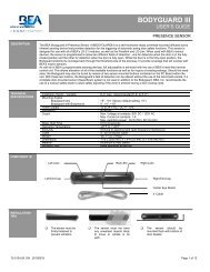
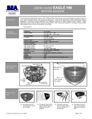
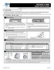
2 <strong>Specifications</strong> (Continued)DESCRIPTION MOTION SENSOR PRESENCE SENSORDetection modeMinimum detection speed2 inches / sec. (measured in the sensor axis)Response time: < 128msAngle From 15° to 50° in elevation (adjustable) From - 4° to + 4° (adjustable)Output specificationRelay (free of potential change-over contact):• Max contact voltage: 42V AC/DC• Max contact current: 1A (resistive)• Max switching power: 30W (DC) / 60VA (AC)Output hold-time 0.5s to 9s (adjustable) 1s (fixed)Manual adjustmentRemote control adjustments• orientation of sensing field (mechanically)• shape of the sensing field (choice of antenna)• multiple functions (using push buttons)• Sensitivity• Hold time• Detection mode• Immunity• Output configurationTransistor (optocoupled transistor)• Max output current: 100 mA• Max switching power: 48 VDC• orientation of sensing field• shape of the sensing field (choice of front lens)• multiple functions (by push buttons)• Immunity• Auto-learn time• Monitoring mode• Number of Curtains• Relay / Output configuration3 PrecautionsShut off all power before attempting any wiring procedures.Maintain a clean & safe environment when working in public areas.Constantly be aware of pedestrian traffic around the door area.Always stop pedestrian traffic through the doorway when performing tests that may result in unexpected reactions by thedoor.ESD electrostatic discharge: Circuit boards are vulnerable to damage by electrostatic discharge. Before handling any boardensure you dissipate your body’s charge.Always check placement of all wiring before powering up to insure that moving door parts will not catch any wires and causedamage to equipment.Ensure compliance with all applicable safety standards (i.e. ANSI A156.10 / 19) upon completion of installation.DO NOT attempt any internal repair of the sensor. All repairs and/or component replacements must be performed by BEA,Inc. Unauthorized disassembly or repair:1. May jeopardize personal safety and may expose one to the risk of electrical shock.2. May adversely affect the safe and reliable performance of the product will result in a voided product warranty.4 Pre Installation Check1. When preparing to wire multiple devices together for a ‘System’ configuration, it is best to ensure the correct operation of each device independentlybefore starting to help reduce troubleshooting time later in the event of a discrepancy.2. Prior to installing any equipment, ensure the correct line voltage and stability. When applying equipment on a new installation utilizing newelectrical supply circuits, always ensure that correct line voltage exists and is stable. Remember to shut the power back off after this ischecked and before performing any wiring to the system.5 Installation1 Remove Sensor Cover1. Remove cover from unit by gently prying the tab on the backside ofthe sensor housing or if the sensor is installed on the header inserta screwdriver behind the unit and gently pry off the cover.TabPryPage 2 of 15 75.5640.02 20110330