

Enigma/Odyssey installation manual - MGL Avionics
Enigma/Odyssey installation manual - MGL Avionics
Enigma/Odyssey installation manual - MGL Avionics

Create successful ePaper yourself
Turn your PDF publications into a flip-book with our unique Google optimized e-Paper software.
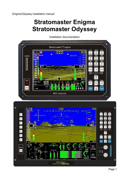
<strong>Enigma</strong>/<strong>Odyssey</strong> <strong>installation</strong> <strong>manual</strong><br />
Stratomaster <strong>Enigma</strong><br />
Stratomaster <strong>Odyssey</strong><br />
Installation documentation<br />
Page 1
<strong>Enigma</strong>/<strong>Odyssey</strong> <strong>installation</strong> <strong>manual</strong><br />
Table of Contents<br />
General................................................................................................................................. 3<br />
<strong>Enigma</strong> and <strong>Odyssey</strong> rear panel.......................................................................................... 3<br />
Connectors on <strong>Enigma</strong> and <strong>Odyssey</strong>............................................................................... 3<br />
<strong>Odyssey</strong> specific connectors............................................................................................ 4<br />
<strong>Enigma</strong> and <strong>Odyssey</strong> electrical <strong>installation</strong>.......................................................................... 7<br />
Installation tips:............................................................................................................ 9<br />
Typical RDAC connection.............................................................................................. 11<br />
Changing the backup battery......................................................................................... 11<br />
Preventing EMI issues................................................................................................... 13<br />
AOA ports....................................................................................................................... 15<br />
Ergonomic considerations.............................................................................................. 17<br />
Transponder interface wiring.......................................................................................... 18<br />
Transponder connections for popular models................................................................ 19<br />
Audio wiring........................................................................................................................ 21<br />
RCA connectors................................................................................................................. 22<br />
Page 2
<strong>Enigma</strong>/<strong>Odyssey</strong> <strong>installation</strong> <strong>manual</strong><br />
General<br />
This document describes the <strong>installation</strong> requirements for a <strong>MGL</strong> <strong>Avionics</strong> Stratomaster<br />
<strong>Enigma</strong> or Stratomaster <strong>Odyssey</strong> panel.<br />
Both instrument types share similar <strong>installation</strong> requirements.<br />
<strong>Enigma</strong> and <strong>Odyssey</strong> rear panel<br />
Finding your way around the rear panel<br />
Connectors on <strong>Enigma</strong> and <strong>Odyssey</strong><br />
1<br />
1<br />
2<br />
3<br />
4<br />
5<br />
6<br />
17<br />
19<br />
7<br />
11<br />
10<br />
20 21 22<br />
16<br />
18<br />
8<br />
9<br />
12 13 14<br />
15<br />
Page 3
<strong>Enigma</strong>/<strong>Odyssey</strong> <strong>installation</strong> <strong>manual</strong><br />
<strong>Odyssey</strong> specific connectors<br />
24<br />
25<br />
23<br />
1. USB host connectors<br />
These connectors are used to connect a master panel to a slave panel. The master<br />
is always the host so the host connector of the master connects to the USB device<br />
connector of the slave. Note: The connections you choose here determines which<br />
panel is master and which is slave – no further setup for this is required. Please<br />
note that some slave panel options may need to be setup in the instrument setup.<br />
You can connect up to two slaves to a single master panel. The USB host<br />
connector is also used to connect a communications extender module<br />
1. USB device connector<br />
This connector connects to a master panel or a PC application capable of<br />
communicating with the instrument through USB such as flight simulators<br />
2. RS232 Port 1<br />
This multifunction port is typically used to connect NAV and COM radios or<br />
XRX/PCAS or FLARM traffic monitoring systems.<br />
3. RS232 Port 2 / NMEA<br />
This port is a dedicated NMEA output containing GPS messages intended for your<br />
autopilot or GPS enabled application. Baudrate is 4800 (<strong>Enigma</strong>) and 9600<br />
(<strong>Odyssey</strong>).<br />
<strong>Odyssey</strong> only: The RX of this port can receive NMEA from an external GPS if this is<br />
selected in the instrument setup. External NMEA must be selected at 9600 baud.<br />
4. GPS Antenna<br />
This SMA connector accepts connection of an active GPS antenna. Active GPS<br />
antennas contain a built in amplifier. Supply voltage on this connector is 3.3V. The<br />
output is short circuit protected. A short circuit will switch off the supply voltage. The<br />
instrument needs to be restarted to switch the supply on again.<br />
5. Secured supply output<br />
These two terminals provide power to AHRS, compass sensor, RDACs and IO<br />
Extender. This power is switched to the battery backup (if fitted). Observe maximum<br />
current capability of his output. Over current or shorting this output may damage the<br />
Page 4
<strong>Enigma</strong>/<strong>Odyssey</strong> <strong>installation</strong> <strong>manual</strong><br />
instrument.<br />
6. Backup battery<br />
If required, connect a lead-acid 12V backup battery. Typical capacities are 2-5A/H<br />
depending on your needs. Note that the battery needs to be connected via a switch<br />
(see <strong>installation</strong> drawing in this document). The instrument contains a current and<br />
voltage limited charging circuit. Maximum charge current is 0.5A at 13.8 Volts.<br />
7. Audio output high level<br />
This output contains high level, low impedance audio (voice prompts and alerts).<br />
This output can drive a small 4-8 ohm speaker directly at up to 1W power. This<br />
output can also be connected to intercom panels that accept high level inputs.<br />
8. Audio output low level<br />
This output contains low level high impedance audio intended for intercom panels<br />
that provide low level inputs.<br />
9. Battery cover release<br />
Undo this nylock nut to remove the memory backup battery. The battery is the<br />
common type CR2032. It is used to backup internal memory as well as run the real<br />
time clock. This battery should be changed very two years. Use only reputable<br />
batteries. Beware of badly performing “pirate” batteries.<br />
10.Battery cover<br />
Underneath this cover is the battery holder that holds your memory and clock<br />
backup battery.<br />
11.Airtalk LAN connector<br />
12.Airtalk LAN connector<br />
Connect <strong>MGL</strong> <strong>Avionics</strong> AHRS and compass sensors as well as the I/O Extender<br />
module. The two connectors are internally connected to each other.<br />
13.Main connector<br />
This connector contains the power supply input for the instrument, ambient<br />
temperature probe connection and external alarm switch output.<br />
14.Altitude encoder output<br />
This connector outputs the Gillman code altitude signals for a mode-c transponder.<br />
15.Pitot port<br />
Connect suitable piping to your airspeed pitot tube. Ensure airtight seal.<br />
16.Static port<br />
If required, connect your static port here.<br />
17.AOA+ port<br />
Positive pressure AOA port. Connect to AOA pressure pickup or positive pressure<br />
port<br />
18.AOA- port<br />
Page 5
<strong>Enigma</strong>/<strong>Odyssey</strong> <strong>installation</strong> <strong>manual</strong><br />
Negative pressure AOA port. In case of single port AOA systems connect this to<br />
static pressure. In case of dual (differential) AOA system, connect to negative<br />
pressure port.<br />
19.Rotor speed connector<br />
In case of a rotor craft <strong>installation</strong>, this connector can be used to connect a rotor<br />
speed sensor. The connector provides ground, signal and +12V output to supply a<br />
sensor. The +12V output it connected to incoming supply power. Signal amplitude<br />
is +5V with respect to ground minimum and may be up to supply voltage.<br />
20.RDAC 1 connector<br />
Connect a RDAC engine monitoring subsystem. This is the connection for RDAC 1,<br />
the primary monitor or monitor number one in case of dual engine systems.<br />
21.RDAC 2 connector<br />
Connect a second RDAC monitor sub system for extended monitoring functions or<br />
a second engine.<br />
22. CAN/J1939 connector<br />
This connection is used for the automotive CAN bus used by some engine<br />
management systems.<br />
23.ARINC-429 connector<br />
Three RX (receive) and one TX (transmit) ARINC 429 channels are provided.<br />
RX 1 and RX 3 are normal speed ARINC channels intended for connection to<br />
ARINC enabled NAV and GPS receivers.<br />
RX 2 is a high speed ARINC channel intended for connection of a ARINC 735<br />
compliant traffic monitoring system (TCAS, TIS).<br />
TX is a normal speed ARINC channel intended to connect to ARINC enabled<br />
autopilots.<br />
24.Analog NAV inputs<br />
Four +/- 150mV differential analog inputs are provided to connect to NAV receivers<br />
that provide compatible outputs.<br />
Assignments are as follows:<br />
Channel<br />
Function<br />
1 CDI (Course deviation indication)<br />
2 GS (Glide slope indication)<br />
3 CDI valid flag<br />
4 GS valid flag<br />
Page 6
<strong>Enigma</strong>/<strong>Odyssey</strong> <strong>installation</strong> <strong>manual</strong><br />
<strong>Enigma</strong> and <strong>Odyssey</strong> electrical <strong>installation</strong><br />
Electrical <strong>installation</strong> between <strong>Enigma</strong> and <strong>Odyssey</strong> is nearly identical. <strong>Odyssey</strong> has a few<br />
additional connectors for CAN, ARINC and Analog NAV radio usage.<br />
Page 7
<strong>Enigma</strong>/<strong>Odyssey</strong> <strong>installation</strong> <strong>manual</strong><br />
<strong>Odyssey</strong> rear panel<br />
Page 8
<strong>Enigma</strong>/<strong>Odyssey</strong> <strong>installation</strong> <strong>manual</strong><br />
These images show basic wiring requirements for <strong>Enigma</strong> and the identical set for<br />
<strong>Odyssey</strong>.<br />
In this case a small backup battery is used. Note that two power switches are required.<br />
One power switch for the main incoming 12 or 24 V feed (switch in positive supply lead),<br />
another for the backup battery.<br />
In flight, both switches would be “on” allowing the charging of the backup battery.<br />
Preflight check would involve switching main power on, then battery power on. Check of<br />
battery power would involve switching main power off and verifying that <strong>Enigma</strong> continues<br />
to operate. Voltage on the backup battery should be measured by means of the backup<br />
voltage readouts which can be placed on any display.<br />
In this case the secured supply output is used to power a SP-3, 4 or SP-5 AHRS and/or a<br />
SP-2 compass. This supply will draw from the backup battery in case of main power fail.<br />
Please note that it is not permissible to connect other high current users to this supply<br />
output. Maximum permitted current draw from these terminals is 0.5A. Under no<br />
circumstances connect transceivers or lighting to these terminals.<br />
Recommended backup battery types are 12V sealed lead acid with capacities ranging<br />
from 1Ah to 2.5Ah for <strong>Enigma</strong> and 1.5Ah to 4Ah for <strong>Odyssey</strong>.<br />
Usage of a backup battery is optional. It is not required for normal operation of the<br />
instrument. The secured supply output may be used to supply AHRS and compass<br />
sensors regardless of <strong>installation</strong> of a backup battery.<br />
In case of a dual panel <strong>installation</strong>, it is permissible to connect both panels to a single<br />
backup battery.<br />
Please note that inline fuses or over-current sensing interrupters must be installed as<br />
shown. It is wise to install these in such as way that it is possible to replace fuses in flight<br />
or reset a circuit breaker.<br />
Installation tips:<br />
Avoid ground loops<br />
If you are using <strong>MGL</strong> <strong>Avionics</strong> SP-2,3,4,5 sensors and have them connected to the<br />
instrument via the RCA data cables, the ground connection from the secured supply output<br />
should not be installed. The black ground wire from the SP sensors should remain<br />
unconnected. The ground connection will be established via the RCA cable. A second<br />
ground wire should not be used as this will create a possible ground loop resulting in<br />
possible EMI problems.<br />
If you are using data or signal cables between electrical instruments in your aircraft that<br />
contain ground connections, always route these cables in such a way that no large ground<br />
loops will be created. This can be achieved easily if cables like this are routed in tight<br />
bundles with other ground connections. If you create a physical ground loop that has any<br />
form of physically significant area (i.e. Two ground connections starting at one point, then<br />
separating and finally merging at a second point), such a loop forms a loop antenna. This<br />
can transmit small RF noise signals thatmay be present on the ground and cause radio<br />
interference. At the same time, such a loop can act as effective receive antenna for your<br />
radio transmissions and route the received signals into your electrical equipment. This can<br />
Page 9
<strong>Enigma</strong>/<strong>Odyssey</strong> <strong>installation</strong> <strong>manual</strong><br />
cause feedback issues in radio/intercom systems and can result in disturbances to EFIS<br />
systems.<br />
Never share grounds.<br />
Ground connections to backup battery, AHRS, compass and main supply to the instrument<br />
must never be connected to each other or shared. These must remain individual<br />
connections.<br />
Avoid illegal ground currents<br />
Ensure that all electrical users in your system have individual ground connections to a<br />
central point, for example a ground connection bar to the aircrafts power supply negative<br />
rail.<br />
Some data or signal interconnections between instruments may require that these<br />
instruments grounds are connected via the connecting data or signal cables. This creates<br />
a potential problem that in severe cases can result in damage to your instruments.<br />
Should one of your instruments loose its normal ground connection (for example a VHF<br />
transceiver), it may use grounds through its signal or data cables through other<br />
instruments. These ground connections may not be designed to allow large current flows.<br />
In this example, should you press your PTT to start a transmission, a current of several<br />
amperes may flow through the signal grounds causing potential damage.<br />
<strong>Enigma</strong> and <strong>Odyssey</strong> contain electronic components in the signal and data ground lines<br />
designed to block high frequencies to improve EMI performance. These components are<br />
rated for a maximum DC current of 2 amperes. Should this current be exceeded, these<br />
components may be damaged. Please note that damage to EMI components caused by<br />
over current in ground connections is not covered by warranty. Please ensure that your<br />
aircrafts electrical grounding system is sound and correctly designed.<br />
Always separate RF systems and antenna cables<br />
Radios and antenna cables may be powerful sources of interference to and from EFIS<br />
systems. Always ensure that radios have their own grounds and power supply routing to<br />
your aircrafts power system. Never share these connections with other equipment.<br />
Never route antenna cables into wiring looms. Keep antenna cables separate from ALL<br />
other wiring with some physical distance.<br />
Never mount antenna cables close to the EFIS<br />
Antennas may radiate significant amounts of RF power. If this is allowed to radiate into the<br />
EFIS, malfunction may result. Note that any wires that are attached to the EFIS may route<br />
received energy into the EFIS. Early signs of this are unstable altitude, airspeed and<br />
vertical speed displays while you are transmitting on the radio.<br />
In severe cases the EFIS may perform an emergency shutdown as operational parameters<br />
may be exceeded.<br />
Minimum distance of antenna to EFIS depends on many factors such as your antennas<br />
radiation pattern, effects of your fuselage and output power of your radio.<br />
Page 10
<strong>Enigma</strong>/<strong>Odyssey</strong> <strong>installation</strong> <strong>manual</strong><br />
Typical distances that should be considered are 6-9 ft, closer distances should be<br />
evaluated on a case by case bases.<br />
What to do with excess length of the GPS antenna cable<br />
Should your GPS antenna cable be too long, loop the excess cable into a loop of abut 5-6”<br />
diameter. Then flatten the loop leaving two loops at the end with about 1.5” diameter and<br />
secure in this way using two or three cable ties. Flattening the loop avoids creating a<br />
pickup loop for RF interference which may be routed to the EFIS via the antenna cable.<br />
Image showing correct method to bundle excess cable length of the GPS Antenna<br />
Typical RDAC connection<br />
This image shows a typical RDAC wire connection. Ensure that the wires tips are correctly<br />
stripped. We recommend that the wires be tinned using a soldering iron and electronic<br />
solder wire (do not use acid flux).<br />
Tighten the terminal screws but do not over-tighten.<br />
These are special terminals containing friction locks<br />
that prevent loosening under thermal changes and<br />
vibration.<br />
Changing the backup battery<br />
Every two years, replace the backup battery. This is a type CR2032 as used often in<br />
calculators. Obtain a replacement battery from a reputable manufacturer.<br />
Have your new battery ready. Remove the old battery (push the clip downwards to release<br />
the old battery, then insert the new battery by inserting into the top first and then pressing<br />
down on the battery to clip it into position.<br />
If you perform this within 1 minute you will not loose any data, however we recommend<br />
that you copy your flight log and any routes that you may have stored on the internal RAM<br />
Page 11
<strong>Enigma</strong>/<strong>Odyssey</strong> <strong>installation</strong> <strong>manual</strong><br />
drive to a SD card in case you do loose this data during the battery replacement.<br />
Do not wait until the battrey is empty before replacing it.<br />
An empty battery results in your instruments date and time<br />
starting from 1. January at 00:00 every time you switch on<br />
your instrument. Further to this, you will loose your<br />
calculated fuel tank levels, accumulated fuel burn values,<br />
flight log and routes.<br />
Loosen this nut<br />
Observe battery polarity as shown in this image<br />
Lower this clip<br />
to release battery<br />
Page 12
<strong>Enigma</strong>/<strong>Odyssey</strong> <strong>installation</strong> <strong>manual</strong><br />
Preventing EMI issues<br />
This image shows a photo of a typical, principle <strong>installation</strong> wiring on a MK-1 <strong>Enigma</strong>. Note<br />
the use of ferrite beads on ALL wires leaving the instrument. Ferrite beads are effective to<br />
eliminate any RF interfering signals that may cause radio interference particularly on VHF<br />
radios.<br />
Beads may or may not be required, this will depend highly on <strong>installation</strong> and routing of<br />
wiring in the aircraft. As a rule, follow these guidelines:<br />
• Antenna cables must never be routed alongside other wiring.<br />
• Place antennas as far away from any digital instrumentation as possible.<br />
• Avoid ground loops which can act as powerful, short range transmitting aerials for<br />
weak signals. Ensure that your aerial has a good and correct ground plane.<br />
• Never share power or ground cables between RF equipment and digital equipment.<br />
Each requires their own routing of power to the battery.<br />
Notes on the use of ferrite beads:<br />
Install ferrite beads close to the source of interference. It does not help much if there is two<br />
meters of cable between source and ferrite bead. Distances as shown in the photo are<br />
correct.<br />
Page 13
<strong>Enigma</strong>/<strong>Odyssey</strong> <strong>installation</strong> <strong>manual</strong><br />
Multiple wires may share a single ferrite bead with the exception of the GPS aerial antenna<br />
which requires a ferrite on its own.<br />
In case of the GPS aerial, loop the cable twice through the ferrite. Notice the size of the<br />
loops. Never loop this cable tightly, you will greatly reduce the sensitivity and performance<br />
of the GPS system if you do. The size of the loops in the photo is correct.<br />
Other wiring should be looped tightly as shown in the photo.<br />
The more loops you can place around a ferrite, the better the effect.<br />
Please note again that ALL wires leaving the instrument should have a ferrite bead if you<br />
have problems with RF interference.<br />
Identifying RF interference sources:<br />
<strong>Enigma</strong> creates a signal that is highly dependent on the contents of the display and may<br />
sound like an “angry grrrrrr”. If you have radio noise, change the screens to see if the<br />
noise pattern changes as well. If it does, start identifying which cables are used to transmit<br />
the noise to your radio. <strong>Enigma</strong> itself does not transmit a significant signal due to strict EMI<br />
design techniques however, small signals may readily leak and use any attached wires as<br />
convenient antenna for transmission. Thus, remove the wires one by one. Start with the<br />
GPS – this is a long wire and may contribute significantly. You can remove this wire with<br />
the instrument switched on. Then try the audio and airtalk cables which can be unplugged<br />
easily, This way you will quickly find the source. Place ferrites as needed or reroute the<br />
cable to improve the situation.<br />
A good <strong>installation</strong> should not generate any noticeable RF interference on your VHF radio<br />
with the squelch fully opened, you should hear only static noise.<br />
Note that inside metal hangers noise interference may be considerably worse in some<br />
cases. Always check outside a hanger and move at least 100 ft away from any hanger<br />
structure.<br />
Page 14
<strong>Enigma</strong>/<strong>Odyssey</strong> <strong>installation</strong> <strong>manual</strong><br />
AOA ports<br />
<strong>Enigma</strong> and <strong>Odyssey</strong> can be used with two different kinds of AOA measurement systems,<br />
single or dual ported. These are referred to as Relative or Differential systems. Once you<br />
have decided which of the port types you will be using, select your choice in the “Flight<br />
instruments setup” of your instrument. You instrument needs to know which type you are<br />
using. The following drawings show the various types. Exact mechanical dimensions are<br />
not critical.<br />
Correct operations of the AOA system is subject to a calibration flight. Please view the<br />
relevant section in the user <strong>manual</strong> on how to perform the calibration flight. We<br />
recommend that the AOA indications are checked regularly by briefly increasing angle of<br />
attack during save flight and verifying correct indications.<br />
Page 15
<strong>Enigma</strong>/<strong>Odyssey</strong> <strong>installation</strong> <strong>manual</strong><br />
Photo of an experimental single port AOA<br />
probe mounted next to the pitot tube on the<br />
wing strut of our Jora aircraft. This probe,<br />
made from wood, works very well indeed.<br />
Page 16
<strong>Enigma</strong>/<strong>Odyssey</strong> <strong>installation</strong> <strong>manual</strong><br />
Ergonomic considerations<br />
<strong>Enigma</strong> and <strong>Odyssey</strong> contain very advanced LCD display that are able to perform well in<br />
direct sunlight conditions. In order to achieve this and further ensure low power<br />
consumption, the display contains a “light director”. This focuses the major part of<br />
available light towards the viewer, creating a brighter image but also reducing the effect of<br />
ambient light falling at an angle onto the display surface.<br />
<strong>Odyssey</strong> is designed with a 0 to +40 degree viewing angle to favor traditional vertical<br />
instrument panels.<br />
<strong>Enigma</strong> is designed for optimum viewing angle of -30 to +25 degrees. In order to take<br />
optimum advantage of this, the panel should be installed such that the pilots eye will look<br />
onto the panel in a vertical -30 to +25 degree angle maximum. The negative angle would<br />
be applicable for a steeply sloped panel where you would be looking onto the panel from<br />
below.<br />
This can be achieved in two ways: Mount the instrument as high as possible onto the<br />
panel. This also aids the pilot as the image is closer to the windscreen avoiding eye fatigue<br />
while constantly changing view from the panel to outside the aircraft.<br />
If this is not possible or can only be done in a limited way, consider tilting the instrument up<br />
slightly in order to aim the picture towards the pilot.<br />
Idealized view of a sloped panel to optimize viewing quality. This image overdoes this<br />
somewhat, in practice the panel does not have to be angled this much and if it is possible<br />
to install the instrument relatively high on the panel, it is not normally required to mount the<br />
instrument angled.<br />
Preferred horizontal viewing angles are within left 50 degrees to right 50 degrees. If a<br />
single instrument is to be shared between two pilots seated side by side, consider<br />
<strong>installation</strong> of the instrument towards the center of the panel or alternatively angle it<br />
towards the disadvantaged side somewhat. The panel can be read as angles greater than<br />
Page 17
<strong>Enigma</strong>/<strong>Odyssey</strong> <strong>installation</strong> <strong>manual</strong><br />
+/-50 degrees but with reduced brightness.<br />
Transponder interface wiring<br />
The transponder interface produces Gillman (Gray) coded altitude information suitable for<br />
connection to a mode C transponder.<br />
Connections using the standard code identifiers are shown here. If your transponder does<br />
not support signals D4 and D2, leave them unconnected. At least one of the ground wires<br />
should be connected to the corresponding ground terminal of your transponder.<br />
Page 18
<strong>Enigma</strong>/<strong>Odyssey</strong> <strong>installation</strong> <strong>manual</strong><br />
Transponder connections for popular models<br />
Page 19
<strong>Enigma</strong>/<strong>Odyssey</strong> <strong>installation</strong> <strong>manual</strong><br />
Transponder interface wiring for Microair T2000 (ignore pin numbers on DB15 connector).<br />
Also line “Encoder power” is not used with <strong>Enigma</strong>.<br />
Page 20
<strong>Enigma</strong>/<strong>Odyssey</strong> <strong>installation</strong> <strong>manual</strong><br />
Audio wiring<br />
<strong>Enigma</strong> and <strong>Odyssey</strong> provide two related audio outputs. These outputs carry voice<br />
messages and alerts and other signals. One of the audio outputs is able to drive a small<br />
loud speaker directly. The other output caries a low level signal intended to be fed into<br />
intercom systems that have a low level input. The high level output can often be used<br />
directly with intercom systems that provide high level inputs only.<br />
The audio outputs are not provided with internal volume control or mute. It is intended that<br />
mute and/or volume controls are provided either as part of the audio intercom panel or<br />
they can be easily added with components easily obtainable from electronic parts shops<br />
as shown in the following images:<br />
This image shows the usage of a<br />
potentiometer to be used as volume<br />
control. Here it is used plugged into the<br />
high level audio output. If a low resistance<br />
potentiometer is used (for example 50<br />
ohms, 1W power capable), it can be used<br />
to control the volume of an attached 4 or 8<br />
ohm speaker.<br />
If you are connecting to an intercom<br />
system or audio panel that does not allow<br />
volume control, you can likely use higher<br />
value resistance potentiometers but we<br />
recommend no to go larger than about<br />
1KOhm (1000 Ohms) in order to keep<br />
impedances low which makes the audio<br />
system more resistant to interference from<br />
other electrical systems.<br />
This image shows an alternative<br />
arrangement if you want to install a panel<br />
switch to mute the audio signal. In this<br />
case a small SPDT switch has been used.<br />
In the muted position the audio input of the<br />
intercom system or audio panel is<br />
connected to ground (shorted) to avoid<br />
pickup of electrical noise.<br />
Should you want to use a switch with a<br />
speaker, you can use a simple switch to<br />
disconnect the speaker as required.<br />
Page 21
<strong>Enigma</strong>/<strong>Odyssey</strong> <strong>installation</strong> <strong>manual</strong><br />
Both of the above image show a suggested <strong>installation</strong> of a small ring ferrite in the audio<br />
line. Ferrites provide a RF block for high frequency signals received on the cables from<br />
radio transmissions. These signals can cause interference in particular with audio<br />
systems. It is advisable to loop the cable a few times through the ferrite as shown. Ferrites<br />
are obtainable from electronics shops. Ensure that the ferrite is suitable for the high<br />
frequencies used with VHF radios such as NiZn ferrites,<br />
Ferrites may be required particularly in tight <strong>installation</strong>s where radios, antennas and<br />
sensitive equipment are in close proximity.<br />
RCA connectors<br />
RCA connectors are used for audio connections as well as for the Airtalk local area<br />
network.<br />
We recommend that good quality plugs/cables are used. Poor quality plugs may not seat<br />
tightly and may dislodge. Poor quality cables may give intermittent contacts.<br />
Good quality RCA plugs and cables can be obtained from vendors that provide audio and<br />
video equipment. Do not buy expensive cables – these will not give you any benefit.<br />
Two types of common RCA connectors. The type on the left tends to have poor holding<br />
power and may need to be secured from departing the RCA socket in flight. Some types<br />
like this can be improved by bending the four tabs slight inwards to improve holding power.<br />
The type on the right is generally much better giving a tight and firm fit that is unlikely to<br />
loosen itself from the RCA socket in flight.<br />
Page 22


