


Create successful ePaper yourself
Turn your PDF publications into a flip-book with our unique Google optimized e-Paper software.
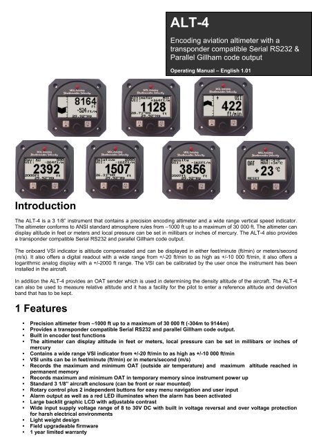
<strong>ALT</strong>-4Encoding aviation altimeter with atransponder compatible Serial RS232 &Parallel Gillham code outputOperating <strong>Manual</strong> – English 1.01IntroductionThe <strong>ALT</strong>-4 is a 3 1/8” instrument that contains a precision encoding altimeter and a wide range vertical speed indicator.The altimeter conforms to ANSI standard atmosphere rules from –1000 ft up to a maximum of 30 000 ft. The altimeter candisplay altitude in feet or meters and local pressure can be set in millibars or inches of mercury. The <strong>ALT</strong>-4 also providesa transponder compatible Serial RS232 and parallel Gillham code output.The onboard VSI indicator is altitude compensated and can be displayed in either feet/minute (ft/min) or meters/second(m/s). It also offers a digital readout with a wide range from +/-20 ft/min to as high as +/-10 000 ft/min, it also offers alogarithmic analog display with a +/-2000 ft range. The VSI can be calibrated by the user once the instrument has beeninstalled in the aircraft.In addition the <strong>ALT</strong>-4 provides an OAT sender which is used in determining the density altitude of the aircraft. The <strong>ALT</strong>-4can also be used to measure relative altitude and it has a facility for the pilot to enter a reference altitude and deviationband that has to be kept.1 Features• Precision altimeter from –1000 ft up to a maximum of 30 000 ft (-304m to 9144m)• Provides a transponder compatible Serial RS232 and parallel Gillham code output.• Built in encoder test functions• The altimeter can display altitude in feet or meters, local pressure can be set in millibars or inches ofmercury• Contains a wide range VSI indicator from +/-20 ft/min to as high as +/-10 000 ft/min• VSI units can be in feet/minute (ft/min) or in meters/second (m/s)• Records the maximum and minimum OAT (outside air temperature) and maximum altitude reached inpermanent memory• Records maximum and minimum OAT in temporary memory since instrument power up• Standard 3 1/8” aircraft enclosure (can be front or rear mounted)• Rotary control plus 2 independent buttons for easy menu navigation and user input• Alarm output as well as a red LED illuminates when the alarm has been activated• Large backlit graphic LCD with adjustable contrast• Wide input supply voltage range of 8 to 30V DC with built in voltage reversal and over voltage protectionfor harsh electrical environments• Light weight design• Field upgradeable firmware• 1 year limited warranty
<strong>ALT</strong>-4 operating <strong>Manual</strong> Page 22 <strong>ALT</strong>-4 LayoutDB15 Encoder Output:Gillham parallel output to transponderLED Alarm:The red LED will illuminate if thedeviation band has been exceededwhen using the deviation altitude modeBacklit Graphic LCD Display:Contrast and backlight canbe adjusted in the menu systemPressure Ports:Pressure ports connectto the static pressure tubeUp/F1 Button:Up button in menu systemDeviation mode: EnterReference altitude anddeviation bandRelative Mode: Enter referencealtitudeHarness:Harness connectsto powerDown/F2 Button:Down button in menusystemMain display scrolling inNormal modeRotary Control (Up/Down) & Enter Button:Press the rotary control during normal mode to access the menu system. Rotateanti/clockwise for up/down menu scrolling. During normal mode rotating the rotarycontrol will adjust the local pressure setting. Local pressure can be set in either mBor in “Hg.3 Main DisplayThe main displays can be toggled by pressing the F2/Down key.3.1 Altitude and VSI displayAltitude ReadingLogarithmic analogVSI indicatorAltitude UnitVSI UnitLocal pressure readout (either inmillibars or in inches of mercury)Digital VSI readout
<strong>ALT</strong>-4 operating <strong>Manual</strong> Page 33.2 Altitude relative to sea level displayThis is the standard display for the <strong>ALT</strong>-4. Use the rotary control to adjust the local pressure setting.Digital VSI readout,can be turned off inthe menu systemAltitude relative tomean sea levelBarometer, canbe turned off inthe menu systemLocal pressure readout (either inmillibars or in inches of mercury)Altitude unit3.3 VSI (Vertical Speed Indicator)The <strong>ALT</strong>-4 can be setup to be used as a VSI (vertical speed indicator).Logarithmic analogVSI indicatorDigital VSI readoutVSI units3.4 Deviation Altitude displayAltitude deviationfunction on/offAltitude deviationbandDisplay messages when bandhas been exceededDigital VSI readout,can be turned off inthe menu systemReference AltitudeLocal pressure readout (either inmillibars or in inches of mercury)Altitude unit
<strong>ALT</strong>-4 operating <strong>Manual</strong> Page 4Use the rotary control to adjust the local pressure setting. Pressing the F1/up key will allow the pilot to enter a referencealtitude and the deviation band.Adjust the reference altitude using the rotary control. This is the altitude that the pilot wants tomaintain. Press the F1 key to accept, press the F2 key to return to the main display.Adjust the deviation band above and below your reference altitude that is still acceptable to fly in.Any altitude outside this band will activate the alarm. Press the F1 key to accept, press the F2button to return to the main display.Select whether you want the altitude deviation feature enabled or not. Press the F1 key to enablethe altitude deviation feature, press the F2 key to disable the altitude deviation feature.3.5 Relative Altitude displayDigital VSI readout,can be turned off inthe menu systemReference AltitudeBarometer, can beturned off in themenu systemAltitude unitLocal pressure readout (either inmillibars or in inches of mercury)Use the rotary control to adjust the local pressure setting. Pressing the F1/up key will allow the pilot to enter a referencealtitude.Enter the reference altitude you would like to use in relative mode. Use the rotary control to adjustthe reference altitude. Press the F1/up key to accept.3.6 Density Altitude displayDensity altitude is a perceived altitude that pertains to your current altitude and temperature (and to a lesser extent onyour current moisture content of the air). Density altitude is relevant for performance calculations of your aircraft. Densityaltitude affects the performance of your engine, propeller and airfoils. The most noticeable affects of density altitude arelength of take-off and landing runs and the ability of your aircraft to carry weight. There are several methods to calculatedensity altitude, all result in readings that are very close to each other. We decided to implement a popular formula that isoften used by pilots to calculate density altitude at their location.
<strong>ALT</strong>-4 operating <strong>Manual</strong> Page 5Da = Density altitudePa = Pressure altitudeT = ambient temperature in degrees CTs= 15 - 0.0019812 * pressure altitude (ft)Da = Pa + 118.6 * (T-Ts)Digital VSI readout,can be turned off inthe menu systemCompensateddensity altitudevalueAltitude unitUncompensatedaltitude valueLocal pressure readout (either inmillibars or in inches of mercury)3.7 OAT (Outside air temperature) DisplayThe OAT probe is used to determine density altitude. Press the F1 key to reset the min/max reading to the currentreading.OAT readingTemporary maximum andminimum OAT sinceinstrument power upTemperature unit4 Menu SystemPressing the rotary control button during the normal display mode will cause the <strong>ALT</strong>-4 to enter the menu system. Use theup/down keys or the rotary control to navigate through the menu system.
<strong>ALT</strong>-4 operating <strong>Manual</strong> Page 6Note: (ADC Values and Calibrate Menus are only visible when powering up the unit and pressing theRotary Control). The text “CALIBRATE” will appear on the intro screen when entering this mode.Warning: The Calibrate Menu is for technical personnel only. Changing any values in this menu maycause the instrument to display incorrect information, and may require the instrument to be returned tothe factory for recalibration.4.1 Exit MenuPress the rotary control on this menu item to exit the menu system. All changes made duringnavigation of the menu system will be saved in non-volatile memory on exiting the menu system.If you remove power before exiting the menu the instrument will not save any changes.4.2 Maximum ValuesTo avoid false recordings, the maximum values function is only activated 10 seconds after theinstrument has powered up.Move the highlight over the “DONE” menu item and press the rotary button to return to the mainmenu.Move the highlight over this menu item and press the rotary button to reset the maximum altitudeand OAT values to the current values.4.3 Display SetupMove the highlight over this menu option and press the rotary button to return to the main menu.Select this menu option to adjust the display contrast.
<strong>ALT</strong>-4 operating <strong>Manual</strong> Page 7Select this menu option to turn the backlight on or off.Select whether you want the OAT to be displayed in degress Fahrenheit (ºF) or in degreesCelcius (ºC).4.4 Altitude SetupAll altitude related parameters can be setup here.Move the highlight over the “DONE” menu item and press the rotary button to return to the mainmenu.Select if you want your altitude readout in feet (ft) or meters (m).Select if you want your local pressure readout in millibars (mB) or inches of mercury (“Hg).Select if you want the barometer to be displayed on the altitude screens or not.Select the protocol of the RS232 output message. The protocol can be selected betweenGARMIN AT, Magellan, Northstar/Garmin, Trimble/Garmin, <strong>MGL</strong> <strong>Avionics</strong> and Microair UAV.Please see section 5 for more information.Select the resolution of the output data, a selection of 1,10,25 or 100 ft can be made.This is a handy function to test the <strong>ALT</strong>-4 transponder interface once installation has beencompleted.
<strong>ALT</strong>-4 operating <strong>Manual</strong> Page 84.4.1 Encoder test functionThis is a handy function to test the <strong>ALT</strong>-4 transponder interface once installation has been completed. Both the parallelGillham and Serial RS232 outputs can be tested. The <strong>ALT</strong>-4 will resume the normal output of the indicated altitude uponexiting the test function.Move the highlight over the “DONE” menu item and press the rotary button to return to the mainmenu.Warning: Do not use this function while in flight as incorrect altitude information will be sent tothe transponder.Ripple TestThe ripple test is for the parallel Gillham output only. This test will continuously loop and assertone line at time starting at the C4 output line and ending in the D4 output line. This test is handyto see if all lines are correctly connected from the <strong>ALT</strong>-4 to the transponder.The line that is currently asserted is displayed on the screen. Press the F1/Up key to exit the test.Altitude TestThe altitude test can be used to test both the Serial as well as the parallel Gillham output. Thealtitude test allows the installer to key in a desired altitude and to see if the transponder altitudecorresponds.The installer can put the <strong>ALT</strong>-4 into an auto test mode or a manual test mode. The auto mode willincrement the altitude at 100ft per second from -1200 to 30000. In the manual mode the installercan rotate the rotary control to a desired altitude. Press the F1/Up key to exit the test.4.5 VSI (Vertical Speed Indicator) SetupAll VSI related parameters can be setup here.
<strong>ALT</strong>-4 operating <strong>Manual</strong> Page 9Move the highlight over the “DONE” menu item and press the rotary button to return to the mainmenu.This function is used to set your VSI to read exactly 0ft/min. This is similar to setting the needleon a mechanical VSI to point to zero by turning the adjustment knob on such a VSI. Theelectronic VSI generally has much less drift compared to a mechanical VSI and this function willonly be used very occasionally. Ensure that you perform this function when no pressure changesdue to wind or other reasons are occurring.Select if you want to show the built in VSI (vertical speed indicator). The built in VSI will be shownabove the altitude readout.Select if you want your VSI readout in feet/minute (ft/m) or meters/second (m/s).Note: meters/second will be shown with two decimals, example: “1.23”.This is a function that is used to calibrate your VSI to read exact rates of climb or decent. Thisfunction works as a percentage of initial reading. The default setting for this function is 100%.Increasing this value increases the VSI reading and decreasing the value decreases the reading.Suggested VSI calibration methodAfter you have installed the instrument, perform a calibration flight. This should be done in very calm conditions.Turbulence and thermal activity will make accurate calibration impossible. Many areas have ideal conditions during earlymornings or late afternoons. Place the instrument in “feet” unit mode for ease of calibration. Take your aircraft to a fewthousand feet above ground and start a glide with a low power setting. Take a stopwatch and when the glide is stable(stable VSI reading) start the stopwatch. Take note of your altimeter reading at the same time. Continue the stable glidefor one minute exactly. After the minute has finished, take another reading of your altimeter.Example:VSI reading during stable glide: -400 ft/minStart altitude: 2500 ft.End altitude: 2050 ft.In the above example the VSI is under reading by about 12%. Set your VSI calibration to 112% to cancel out the error.4.6 ADC ValuesNote: This menu item is for technical personnel only, and is not displayed during the normaloperation of the instrument. Please see section 4 above on how to access this menu item.This menu displays the ADC values that have been read from the pressure sensors.
<strong>ALT</strong>-4 operating <strong>Manual</strong> Page 11pressure), L, local pressure setting inmillibars,+/-, four digit VSI reading rightjustified zero padded in ft/min, X,checksum, carriage returnThe checksum is a simple modulo 256 sumof the binary values of the individualcharacters. The checksum is sent as twocharacters in hexadecimal formatMicroair UAV 9600 STX,a,=, five altitude digits right justifiedzero padded, ETXSTX=0x02ETX=0x03CR=0x0D[STX]a=02372[ETX]6 Parallel Gillham transponder connectionThe <strong>ALT</strong>-4 has a parallel output Gillham interface that can be directly connected to various parallel input transponderssuch as those from Garmin, Becker, King, Microair, etc. The output data contains the current pressure altitude with a fixedreference to 1013.25mB (29.92 inches mercury). The following table shows the connection between the <strong>ALT</strong>-4 and thetransponder. See installation section 11 below for more information.Transponder A1 A2 A4 B1 B2 B4 C1 C2 C4 StrobeARCRT359A/459A/859A14 13 15 19 17 16 21 18 20 DisableBECKER ATC2000/340116 15 14 17 19 18 22 21 20 DisableBECKER ATC 4401 1 2 3 14 15 16 17 18 19 DisableBENDIX TRP-2060/2061/6604 6 8 9 10 11 3 5 7 DisableBENDIXTR541A/641BA B C D E F H J K DisableCOLLINS TDR-950/950L12 10 7 6 5 4 8 11 9 DisableEDO-AIRE RT-777 7 5 3 12 13 14 8 6 4 2GARMIN 320/320A/3273 5 6 9 11 12 10 4 7 DisableGENAVE BETA50004 5 6 7 8 9 10 11 12 3KING KT76/78 6 7 9 4 1 2 3 8 10 DisableKINGKT76A/78A/76C/79M K J E C B D L H DisableKING 750A G H J K L M P R S DisableKING KT75 6 7 8 9 10 11 12 13 14 5MICROAIR T2000 9 10 11 12 13 17 18 19 20 DisableNARCO AT50/50A/1507 6 8 12 10 9 14 11 13 5NARCO AT5/6/6A 2 4 8 9 10 11 1 3 5 12RADAIR 250 7 6 13 9 10 11 14 16 12 19TERRATRT250/250D5 17 16 15 2 14 3 4 18 12UPS/APPLLO SL70 13 31 12 33 14 32 16 34 15 DisableWILCOX 1014A K C W T L D P F Z Disable
<strong>ALT</strong>-4 operating <strong>Manual</strong> Page 127 Loading factory default settingsPressing and holding the F1 and F2 simultaneously on power up will cause the <strong>ALT</strong>-4 to load preprogrammed factorydefault settings. The following screen will be displayed:8 Operating the alarmsIf the alarm is activated, the corresponding item on the display will flash. At the same time the externally available alarmswitch will close. The switch will remain closed until any button is pressed to acknowledge the alarm or until thecondition(s) that activated the alarm no longer exist. The alarm output can be used to switch an external alarm indicator.The external alarm switch is an open collector transistor switch to ground with a maximum rating of 0.5A DC. It is possibleto wire the alarm contacts of several Stratomaster instruments in parallel should this be desired. To avoid false activationof the alarms, the alarm function is only active 10 seconds after the instrument has powered up.9 CleaningThe unit should not be cleaned with any abrasive substances. The screen is very sensitive to certain cleaning materialsand should only be cleaned using a clean, damp cloth.Warning: The <strong>ALT</strong>-4 is not waterproof, serious damage could occur if the unit is exposed towater and/or spray jets.10 <strong>ALT</strong>-4 SpecificationsOperating Temperature Range -10ºC to 50ºC (14ºF to 122ºF)Storage Temperature Range-20ºC to 80ºC (-4ºF to 176ºF)Humidity
<strong>ALT</strong>-4 operating <strong>Manual</strong> Page 13Digital VSI resolutionAnalog VSI rangeVSI measurement accuracyGillham code portSerial port10ft+/-2000 ft/m, logarithmic scale+/- 2%, relative to calibrationDB15 connector, Open collector darlington driversRS232 voltage levels, transmit only11 InstallationConnect the static port to a suitable static air pressure line. If you have a slow aircraft or an aircraft were the internal cabinpressure does not change during flight and is equivalent to the outside air pressure you may find that it is not required toconnect a static port.For installations in typical ultralight aircraft pods, be aware of possible pressure changes inside the pod during flightcaused by ram air or suction effects. This may lead to a false indication of altitude. Often these effects are dependent onthe current angle of attack of the airflow around your pod. You will need to install a suitable static port in these cases.The use of an external 1A fuse is recommended. Connect the supply terminals to your aircrafts power supply. The <strong>ALT</strong>-4can be used on both 12V and 24V without the use of any pre-regulators. Ensure that the supply voltage will not dropbelow 8V during operation as this may result in incorrect readings.11.1 Gillham Encoder transponder interfaceThe <strong>ALT</strong>-4 altimeter will measure altitudes typically to around 42 000 ft, however, this requires a transponder that usessignal D4. Transponders that do not have D4 can only transmit altitudes up to 35000 ft. If your transponder only acceptscodes A1 to C4 then you leave signal D4 unconnected. The <strong>ALT</strong>-4 produces inverted Gillman codes as required byvirtually all transponders. The outputs are open collector types and will sink currents up to a few mA.It is recommended to use shielded cable for the connection between the <strong>ALT</strong>-4 and the transponder if a long cable needsto be used. The shield should be connected to ground at one point only (either on the encoding altimeter side or on thetransponder side).Installation of the wiring requires solder work. This needs to be done using electronic resin flux solder wire and propertemperature controlled soldering stations. Do not attempt this if you are unfamiliar with electronic soldering techniques.Please get professional assistance to do this. Bad connections can result in your transponder broadcasting incorrectaltitude codes.See parallel transponder connection section 6 above for various transponder interface connections.Attention:Your country may have regulations that do not allow you to install a transponder or an encoding altimeteryourself. The installation may have to be performed by an authorized person or company. Please checkyour applicable regulations with your aviation authorities.Important information:Depending on laws and regulations in your country you may not be allowed to install a transponder and associatedequipment yourself. This work may have to be done by a certified AMO or instrument technician.Please check with your relevant authorities.The <strong>ALT</strong>-4 encoding altimeter is uncertified equipment and may normally only be used in uncertified aircraft, homebuiltaircraft and microlights (ultralights). Special operations permits for other aircraft may be required. Please be very awarethat any wiring mistake related to the application of Gillham codes to your transponder will result in incorrect altitudesbroadcast by your transponder. Any installation involving the <strong>ALT</strong>-4 must be checked by a suitably equipped aircraft
<strong>ALT</strong>-4 operating <strong>Manual</strong> Page 14instrument maintenance outfit before operation. Failure to do this may be a criminal offence in your country.11.2 Connection Diagram11.3 <strong>ALT</strong>-4 DB9 Cable connectionsDB 9 Pin Color Function1 Black Ground2 Orange OAT Sensor4 NC Airtalk communication (Not connected).Used for firmware upgrading6 Red 8-30Vdc power9 White Alarm Output
<strong>ALT</strong>-4 operating <strong>Manual</strong> Page 1511.4 <strong>ALT</strong>-4 DB15 Cable connectionsDB 15 PinFunction1 Gillham Output D42 Gillham Output A13 Gillham Output A24 Gillham Output A45 Gillham Output B17 RS232 Transmit output9 Gillham Output B210 Gillham Output B411 Gillham Output C112 Gillham Output C413 Gillham Output C215 Ground11.5 Pressure Port DimensionsABInchesMillimetersMin Max Min Max0.182 0.194 4.62 4.930.420 0.440 10.67 11.1812 WarrantyThis product carries a warranty for a period of one year from date of purchase against faulty workmanship or defectivematerials, provided there is no evidence that the unit has been mishandled or misused. Warranty is limited to thereplacement of faulty components and includes the cost of labor. Shipping costs are for the account of the purchaser.Damage as a result of applying excessive pressure to the pressure ports are excluded from warranty.Note: Product warranty excludes damages caused by unprotected, unsuitable or incorrectly wiredelectrical supplies and or sensors, and damage caused by inductive loads.
<strong>ALT</strong>-4 operating <strong>Manual</strong> Page 1613 DisclaimerOperation of this instrument is the sole responsibility of the purchaser of the unit. The user must make themselves familiarwith the operation of this instrument and the effect of any possible failure or malfunction.This instrument is not certified by the FAA. Fitting of this instrument to certified aircraft is subject to the rules andconditions pertaining to such in your country. Please check with your local aviation authorities if in doubt. This instrumentis intended for ultralight, microlight, homebuilt and experimental aircraft. Operation of this instrument is the soleresponsibility of the pilot in command (PIC) of the aircraft. This person must be proficient and carry a valid and relevantpilot’s license. This person has to make themselves familiar with the operation of this instrument and the effect of anypossible failure or malfunction. Under no circumstances does the manufacturer condone usage of this instrument for IFRflights.The manufacturer reserves the right to alter any specification without notice.Other instruments in the Stratomaster Velocity series<strong>ALT</strong>-3 Encoding aviation altimeter and Vertical speed indicator (VSI)<strong>ALT</strong>-4 Encoding aviation altimeter with Serial RS232 & Parallel Gillham code outputASI-3 Airspeed indicator (ASI) with automatic flight logASX-2 Encoding aviation altimeter and Airspeed indicator (ASI)AV-2 Artificial horizon and magnetic compass indicatorE-1 Universal engine monitorFLIGHT-2 Primary Flight instrumentFF-3 Fuel Computer (single or dual fuel tanks)GF-2 +-10G tilt compensated dual range G-force meterMAP-2 Manifold pressure and RPM IndicatorROTOR-1 Dual Rotor / Engine tachometerRTC-1 Aviation real time clock (RTC), outside air temperature (OAT) and Voltage displayRV-3 Universal engine / Rotor RPM IndicatorTC-2 4-Channel thermocouple (EGT/CHT) indicatorTC-3 12-Channel thermocouple (EGT/CHT) indicatorTP-2 Universal temperature and pressure gauge


